EP0329536A1 - Mit einer Durchflusstrennungseinrichtung versehene obere Einbauten eines Kernreaktors - Google Patents
Mit einer Durchflusstrennungseinrichtung versehene obere Einbauten eines Kernreaktors Download PDFInfo
- Publication number
- EP0329536A1 EP0329536A1 EP89400378A EP89400378A EP0329536A1 EP 0329536 A1 EP0329536 A1 EP 0329536A1 EP 89400378 A EP89400378 A EP 89400378A EP 89400378 A EP89400378 A EP 89400378A EP 0329536 A1 EP0329536 A1 EP 0329536A1
- Authority
- EP
- European Patent Office
- Prior art keywords
- refrigerant
- core
- plates
- internal equipment
- upper internal
- Prior art date
- Legal status (The legal status is an assumption and is not a legal conclusion. Google has not performed a legal analysis and makes no representation as to the accuracy of the status listed.)
- Granted
Links
- 238000000926 separation method Methods 0.000 title claims description 6
- 239000002826 coolant Substances 0.000 claims abstract description 11
- 230000002093 peripheral effect Effects 0.000 claims abstract description 3
- 239000003507 refrigerant Substances 0.000 claims description 39
- 230000000712 assembly Effects 0.000 claims description 9
- 238000000429 assembly Methods 0.000 claims description 9
- 239000000446 fuel Substances 0.000 claims description 4
- 238000006073 displacement reaction Methods 0.000 claims description 2
- XLYOFNOQVPJJNP-UHFFFAOYSA-N water Substances O XLYOFNOQVPJJNP-UHFFFAOYSA-N 0.000 abstract description 5
- 125000006850 spacer group Chemical group 0.000 description 8
- 238000001228 spectrum Methods 0.000 description 5
- 239000000463 material Substances 0.000 description 4
- 230000002745 absorbent Effects 0.000 description 2
- 239000002250 absorbent Substances 0.000 description 2
- 238000010586 diagram Methods 0.000 description 2
- 238000003466 welding Methods 0.000 description 2
- 238000010521 absorption reaction Methods 0.000 description 1
- 239000002131 composite material Substances 0.000 description 1
- 238000010276 construction Methods 0.000 description 1
- 238000001816 cooling Methods 0.000 description 1
- 230000004992 fission Effects 0.000 description 1
- 238000004519 manufacturing process Methods 0.000 description 1
- 230000003071 parasitic effect Effects 0.000 description 1
Images


Classifications
-
- G—PHYSICS
- G21—NUCLEAR PHYSICS; NUCLEAR ENGINEERING
- G21C—NUCLEAR REACTORS
- G21C1/00—Reactor types
-
- G—PHYSICS
- G21—NUCLEAR PHYSICS; NUCLEAR ENGINEERING
- G21C—NUCLEAR REACTORS
- G21C5/00—Moderator or core structure; Selection of materials for use as moderator
- G21C5/02—Details
- G21C5/08—Means for preventing undesired asymmetric expansion of the complete structure ; Stretching devices, pins
-
- G—PHYSICS
- G21—NUCLEAR PHYSICS; NUCLEAR ENGINEERING
- G21C—NUCLEAR REACTORS
- G21C7/00—Control of nuclear reaction
- G21C7/06—Control of nuclear reaction by application of neutron-absorbing material, i.e. material with absorption cross-section very much in excess of reflection cross-section
- G21C7/08—Control of nuclear reaction by application of neutron-absorbing material, i.e. material with absorption cross-section very much in excess of reflection cross-section by displacement of solid control elements, e.g. control rods
-
- Y—GENERAL TAGGING OF NEW TECHNOLOGICAL DEVELOPMENTS; GENERAL TAGGING OF CROSS-SECTIONAL TECHNOLOGIES SPANNING OVER SEVERAL SECTIONS OF THE IPC; TECHNICAL SUBJECTS COVERED BY FORMER USPC CROSS-REFERENCE ART COLLECTIONS [XRACs] AND DIGESTS
- Y02—TECHNOLOGIES OR APPLICATIONS FOR MITIGATION OR ADAPTATION AGAINST CLIMATE CHANGE
- Y02E—REDUCTION OF GREENHOUSE GAS [GHG] EMISSIONS, RELATED TO ENERGY GENERATION, TRANSMISSION OR DISTRIBUTION
- Y02E30/00—Energy generation of nuclear origin
- Y02E30/30—Nuclear fission reactors
Definitions
- the invention relates to upper internal equipment of a nuclear reactor of the type comprising a tank for resisting the pressure of a refrigerant, closed by a removable cover and comprising at least one inlet pipe and at least one coolant outlet pipe located near the cover, a core made up of fuel assemblies and in which the refrigerant circulates from the bottom up, several control clusters actuated by control rods through the reactor cover, said upper internal equipment comprising a collection assembly of the refrigerant leaving the core towards the outlet pipe, and a device for separating the flow rates of the refrigerant comprising control cluster guides and their control rod, interposed between the collection assembly and the heart and comprising a lower plate pierced with passages for the refrigerant leaving the core, an upper plate pierced with holes for passage of the refrigerant to the collection assembly and a non-perforated peripheral shell connecting the plates together.
- control clusters comprise bars containing a parasitic absorption material of neutrons, making it possible to control the reactor, and water displacement bars, advantageously containing fertile material.
- upper internal equipment of a nuclear reactor of the type defined above, including the flow separator device includes spacer tubes connecting the refrigerant passages in the upper and lower plates of the device, tubes placed between the cluster guides.
- the invention aims to provide superior internal nuclear reactor equipment that meets the requirements of practice better than those previously known, in particular in that they allow easy assembly of the cluster guides inside the device for separating the flow rates of flow of refrigerant.
- each cluster guide of the flow separation device comprises an external envelope devoid of coolant passage openings and connected to the upper and lower plates of the device in a substantially sealed manner.
- At least some of the envelopes are fixed to one of the plates and are slidably mounted in the other plate, so as to allow the free expansion of said envelopes in the axial direction.
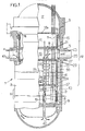
- the pressurized water reactor 1 shown in FIG. 1 has a general constitution similar to that described in document EP-A-0 238 390 to which reference may be made. It comprises a tank 2 for resistance to the pressure of the water constituting the refrigerant, closed by a removable cover 3 and comprising inlet pipes 4 and outlet pipes 5 of the coolant, and a core 6 carried by a lower support plate. 7 piercing of holes 8 for the passage of the refrigerant from bottom to top towards the fuel assemblies of the core, such as the assembly 9.
- Control clusters 10 can be moved vertically by control rods 11 passing through the cover 3 of the reactor 1. These clusters can be of two different types. Some contain absorbent material and are used for piloting. The rest contain fertile material. When they are removed from the heart after irradiation, they give off heat due to the fissions that occur there and must be cooled by circulating refrigerant. Figure 1 shows only two clusters and their stems 11.
- the reactor also includes upper internal equipment 12 interposed between the core 6 and the cover 3.
- Passage means 16 are provided at the level of the flange 15 for diverting a low flow rate of refrigerant arriving through the inlet 4 towards the volume 17 delimited by the cover 3 of the reactor 1 and through the upper part of the upper internal equipment 12 of the reactor .
- This upper part comprises a support for cluster guides 18 in the form of an inverted cap and a spacer 18a for guiding the control rods or their sleeves.
- a collection assembly 19 of the refrigerant leaving the core makes it possible to conduct the latter transversely to heat exchangers external to the reactor by the outlet pipes 5, through holes 20 of the cylindrical casing 13 arranged in line with the outlet pipes 5
- the assembly 19 comprises guide tubes 21 providing passage to the control rods 11 of the clusters 10 and separating the space surrounding the rods from the turbulence of the refrigerant flowing to the pipes 50.
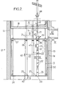
- the upper internal equipment 12 further comprises a device 22 for guiding the cluster and for separating the flow rates (FIG. 2) disposed between the core 6 and the collection assembly 19.
- the device 22 comprises a lower plate 24 pierced with holes 25 for the passage of the refrigerant leaving the core 6 towards the device 22 and pierced with holes 26 for the passage of the control clusters 10. It also includes an upper plate 27 pierced with holes 28 for the passage refrigerant to the collection assembly 19 and to holes 29 for passage of the control rods 11, vertically aligned with the guide tubes 21 and the holes 26. Guides 23 put the passage holes 26 and 29 into communication.
- the two plates 24 and 27 of this device are connected at their periphery by a ferrule 30 so that the whole of the device 22 constitutes a box.
- the rigidity of the box is increased by mechanical elements which connect them. These elements may include spacers 31 rigidly fixed to the plates 24 and 27, and one of which is shown in Figure 2. It is obviously also possible to use more simply some of the guides 23 as spacers, by rigidly fixing them to plates 24 and 27.
- the device 22 for separating the flow rates further comprises the guides 23 intended to protect the clusters 10 and the control rods 11 against the flow of the refrigerant through the device 22 to the assembly 19.
- each cluster guide 23 is for example welded assemblies (FIG. 5) constituted by perforated horizontal plates 32 or "cards” stepped vertically and by continuous guide sleeves 33 3 and square profiles 34 extending over the entire height of the cluster guide and bracing plates 32.
- each cluster guide also comprises an external envelope 35 devoid of coolant passage holes and connected to the lower 24 and upper 27 plates in a substantially sealed manner.
- the channel delimited by this envelope opens up into that formed by one of the guide tubes 21 which extends beyond the support 18 and communicates with the volume 17 directly ( Figure 1) or by calibrated holes, as will be seen further.
- the envelope 35 may, for example, have a substantially hexagonal outline, especially in the case of a tight network. However, other shapes are possible, notably circular and square.
- the square sections 34 and / or the guide sleeves 33 can be fixed to the outer casing 35 in any known way, for example by welding seams 37. But the plates 32 can also be fixed in radial abutment on the envelope 35, for example using additional welded shims.
- the stepped perforated plates 32 can be fixed, for example by pins, directly on the outer casing 35, the square sections 34 being omitted.
- Figure 3 shows a possible constitution of the junction of a cluster guide tube 21 with the upper plate 27.
- the tube 21 is composite. It comprises a guide tube proper 21, the length of which is of the same order as the distance between the plates 18 and 27, and an internal jacket 39 which projects below the upper plate 27 and extends upwards until above the spacer 18a.
- each guide tube 21 are pierced several holes 28 for the passage of the coolant, four or six holes for example, arranged regularly around the hole 29.
- the top of the envelope 35 of each cluster guide can be rigidly fixed, for example by nuts 38, on the lower part of the corresponding inner jacket 39.
- the guides 23 can constitute spacers for joining the plates 24 and 27: they are then rigidly fixed to these plates. But, especially in a spectrum variation reactor, these guides are in overabundant numbers. It is then advantageous to fix some of the envelopes to only one plate, for example by welding, and to mount them sliding in the other plate so as to allow free differential expansion of the envelope in the separation device 22 This arrangement also facilitates the mounting of the envelopes, which can have variable lengths due to manufacturing tolerances.
- Figure 4 shows, by way of non-limiting example, an embodiment of this sliding junction; the casing 35 has an end portion which slides with gentle friction in the hole 26: it can thus expand in the lower plate 24.
- Each hole 26 receives from below the upper end piece 36 of a corresponding fuel assembly 9.
- this nozzle there is made a passage opening of shape corresponding to that of the rods of the cluster, so that, when the latter is inserted, the upward flow of refrigerant is deflected almost entirely as indicated by arrow 40.
- the diameters of the rod 11 and the jacket 39 are proportionally leaving a radial clearance j of a few millimeters of communication between the volume 17 and each cluster guide.
- a local shrinkage of the shirt can however be provided to receive a bulge of the rod when the latter arrives in the low position shown in phantom in Figure 3.
- the play may be greater for the rods of fertile bars of spectrum variation , which require more cooling than the absorbent bars.
- the game is powered in particular by holes 42 drilled in the upper part of the jacket 39, consisting of several parts connected by a threaded connection.
- the game is supplied by holes drilled in a thermal protection sleeve 44 of otherwise known constitution.
- the cold refrigerant enters the reactor 1 through the inlet pipes 4. It is deflected for the most part by the outer casing 13, towards the bottom of the reactor, then it flows from bottom to top through the assemblies 9 of the core 6 of the reactor. The flow leaving an assembly 9 is deflected by the upper nozzle 36 towards the holes 25 opening into the device 22, between the cluster guides 23. The refrigerant then passes through the device 22 between the casings 35 of the cluster guides 23 and spring in the collection assembly 19 through the holes 28. It is deflected there between the guide tubes 21 of the control rods 11, passes through the casing 13 through the holes 20 and leaves the reactor through the outlet pipes 5.
- the refrigerant leaving the assemblies is therefore isolated over its entire path from the refrigerant volumes surrounding the control clusters and their control rods 11, contained in the casings 35 which separate them in a substantially sealed manner from the rest of the device 22, and in the guide tubes 21 which separate them from the refrigerant circulating throughout 17.
- the channels thus formed by the envelopes 35 and the tubes 21 are connected directly to the capacity 17 located under the cover of the reactor, under slight overpressure relative to the refrigerant leaving the assemblies.
- An axial downdraft of refrigerant represented by white arrows 41 in Figures 1 and 2, is therefore present in the tubes 21 and the casings 35. It cools the clusters, which is important if some of them are clusters fertile, as is the case with a spectrum variation reactor. The current also constitutes an aid to the fall of the clusters, which goes in the direction of nuclear safety.
- the passage means 16 allowing a low flow of cold refrigerant to access the capacity 17 located under the cover of the reactor can be simple conduits passing through the flange 15.
Landscapes
- Physics & Mathematics (AREA)
- Engineering & Computer Science (AREA)
- Plasma & Fusion (AREA)
- General Engineering & Computer Science (AREA)
- High Energy & Nuclear Physics (AREA)
- Chemical & Material Sciences (AREA)
- Chemical Kinetics & Catalysis (AREA)
- Monitoring And Testing Of Nuclear Reactors (AREA)
- Structure Of Emergency Protection For Nuclear Reactors (AREA)
- Processing Of Solid Wastes (AREA)
Applications Claiming Priority (2)
| Application Number | Priority Date | Filing Date | Title |
|---|---|---|---|
| FR8801647A FR2627321B1 (fr) | 1988-02-11 | 1988-02-11 | Equipements internes superieurs de reacteur nucleaire muni d'un dispositif de separation des debits |
| FR8801647 | 1988-02-11 |
Publications (2)
| Publication Number | Publication Date |
|---|---|
| EP0329536A1 true EP0329536A1 (de) | 1989-08-23 |
| EP0329536B1 EP0329536B1 (de) | 1992-01-15 |
Family
ID=9363196
Family Applications (1)
| Application Number | Title | Priority Date | Filing Date |
|---|---|---|---|
| EP89400378A Expired - Lifetime EP0329536B1 (de) | 1988-02-11 | 1989-02-09 | Mit einer Durchflusstrennungseinrichtung versehene obere Einbauten eines Kernreaktors |
Country Status (10)
| Country | Link |
|---|---|
| US (1) | US5093075A (de) |
| EP (1) | EP0329536B1 (de) |
| JP (1) | JPH01297595A (de) |
| KR (1) | KR890013661A (de) |
| CN (1) | CN1021161C (de) |
| DE (1) | DE68900688D1 (de) |
| ES (1) | ES2028447T3 (de) |
| FR (1) | FR2627321B1 (de) |
| PT (1) | PT89672B (de) |
| ZA (1) | ZA8901052D (de) |
Cited By (3)
| Publication number | Priority date | Publication date | Assignee | Title |
|---|---|---|---|---|
| EP0477097A1 (de) * | 1990-09-20 | 1992-03-25 | Framatome | Führungseinrichtung für das Kontrollbündel eines Kernreaktors |
| FR2696576A1 (fr) * | 1992-10-05 | 1994-04-08 | Framatome Sa | Equipements internes de réacteur nucléaire à colonnes entretoises et guides de grappe de commande. |
| FR2727560A1 (fr) * | 1994-11-24 | 1996-05-31 | Framatome Sa | Piece tubulaire de traversee du couvercle de la cuve d'un reacteur nucleaire a manchette thermique amelioree |
Families Citing this family (11)
| Publication number | Priority date | Publication date | Assignee | Title |
|---|---|---|---|---|
| CN1080179C (zh) * | 1994-03-24 | 2002-03-06 | 株式会社日本制钢所 | 注模成型机的夹紧装置 |
| US8116423B2 (en) | 2007-12-26 | 2012-02-14 | Thorium Power, Inc. | Nuclear reactor (alternatives), fuel assembly of seed-blanket subassemblies for nuclear reactor (alternatives), and fuel element for fuel assembly |
| UA98370C2 (ru) | 2007-12-26 | 2012-05-10 | Ториум Пауэр Инк. | Ядерный реактор (варианты), топливная сборка из зажигающе-воспроизводящих модулей для ядерного реактора (варианты) и топливный элемент топливной сборки |
| JP5755568B2 (ja) | 2008-12-25 | 2015-07-29 | トリウム・パワー、インクThorium Power,Inc. | 軽水炉核燃料集合体および軽水炉 |
| RU2515501C2 (ru) * | 2009-04-16 | 2014-05-10 | Сирит ЭлЭлСи | Узел управления потоком ядерного реактора деления |
| US8320513B2 (en) | 2009-04-16 | 2012-11-27 | The Invention Science Fund I, Llc | Nuclear fission reactor, flow control assembly, methods therefor and a flow control assembly system |
| WO2011097597A1 (en) * | 2010-02-05 | 2011-08-11 | Smr, Llc | Nuclear reactor system having natural circulation of primary coolant |
| US10170207B2 (en) | 2013-05-10 | 2019-01-01 | Thorium Power, Inc. | Fuel assembly |
| US10192644B2 (en) | 2010-05-11 | 2019-01-29 | Lightbridge Corporation | Fuel assembly |
| WO2011143172A1 (en) | 2010-05-11 | 2011-11-17 | Thorium Power, Inc. | Fuel assembly with metal fuel alloy kernel and method of manufacturing thereof |
| CN108039212B (zh) * | 2017-12-13 | 2024-05-07 | 中国船舶重工集团公司第七一九研究所 | 一种适用于浮动式反应堆的上部堆内构件 |
Citations (4)
| Publication number | Priority date | Publication date | Assignee | Title |
|---|---|---|---|---|
| FR2382747A1 (fr) * | 1977-03-02 | 1978-09-29 | Combustion Eng | Reacteur nucleaire a refroidissement par eau |
| EP0238390A1 (de) * | 1986-03-07 | 1987-09-23 | Framatome | Innere Struktur eines Kernreaktors mit länglichem Druckbehälter |
| EP0240335A2 (de) * | 1986-04-04 | 1987-10-07 | Westinghouse Electric Corporation | Druckwasserreaktor mit verbesserter Innenmantelkonstruktion |
| US4716013A (en) * | 1983-04-29 | 1987-12-29 | Westinghouse Electric Corp. | Nuclear reactor |
Family Cites Families (10)
| Publication number | Priority date | Publication date | Assignee | Title |
|---|---|---|---|---|
| US3861999A (en) * | 1967-04-14 | 1975-01-21 | Combustion Eng | Nuclear reactor arrangement and method of operating safe effective to increase the thermal amargin in high power density regions |
| US3849257A (en) * | 1972-06-28 | 1974-11-19 | Combustion Eng | Guide structure for control elements |
| US4092216A (en) * | 1973-12-14 | 1978-05-30 | Commissariat A L'energie Atomique | Nuclear reactor |
| US4557891A (en) * | 1977-03-02 | 1985-12-10 | Combustion Engineering, Inc. | Pressurized water reactor flow arrangement |
| FR2541810B1 (fr) * | 1983-02-25 | 1989-01-13 | Framatome Sa | Assemblage combustible a tubes-guides refroidis pour un reacteur nucleaire |
| FR2565396B1 (fr) * | 1984-05-30 | 1989-06-30 | Framatome Sa | Procede d'exploitation d'un reacteur a eau legere et a variation de spectre |
| US4681728A (en) * | 1985-03-22 | 1987-07-21 | Westinghouse Electric Corp. | Nuclear reactor |
| US4707331A (en) * | 1985-11-14 | 1987-11-17 | Westinghouse Electric Corp. | Top end support for water displacement rod guides of pressurized water reactor |
| FR2591018B1 (fr) * | 1985-11-29 | 1988-02-19 | Framatome Sa | Guide de grappe a dispositif de centrage et de positionnement antivibratoire pour reacteur nucleaire |
| FR2596563B1 (fr) * | 1986-04-01 | 1990-12-21 | Framatome Sa | Reacteur nucleaire a guidage d'ecoulement dans les equipements internes superieurs |
-
1988
- 1988-02-11 FR FR8801647A patent/FR2627321B1/fr not_active Expired - Lifetime
-
1989
- 1989-02-09 EP EP89400378A patent/EP0329536B1/de not_active Expired - Lifetime
- 1989-02-09 PT PT89672A patent/PT89672B/pt not_active IP Right Cessation
- 1989-02-09 DE DE8989400378T patent/DE68900688D1/de not_active Expired - Lifetime
- 1989-02-09 ES ES198989400378T patent/ES2028447T3/es not_active Expired - Lifetime
- 1989-02-10 JP JP1030061A patent/JPH01297595A/ja active Pending
- 1989-02-10 KR KR1019890001516A patent/KR890013661A/ko not_active Withdrawn
- 1989-02-10 ZA ZA19891052D patent/ZA8901052D/xx unknown
- 1989-02-15 CN CN89102001A patent/CN1021161C/zh not_active Expired - Fee Related
-
1990
- 1990-09-17 US US07/584,442 patent/US5093075A/en not_active Expired - Fee Related
Patent Citations (4)
| Publication number | Priority date | Publication date | Assignee | Title |
|---|---|---|---|---|
| FR2382747A1 (fr) * | 1977-03-02 | 1978-09-29 | Combustion Eng | Reacteur nucleaire a refroidissement par eau |
| US4716013A (en) * | 1983-04-29 | 1987-12-29 | Westinghouse Electric Corp. | Nuclear reactor |
| EP0238390A1 (de) * | 1986-03-07 | 1987-09-23 | Framatome | Innere Struktur eines Kernreaktors mit länglichem Druckbehälter |
| EP0240335A2 (de) * | 1986-04-04 | 1987-10-07 | Westinghouse Electric Corporation | Druckwasserreaktor mit verbesserter Innenmantelkonstruktion |
Cited By (7)
| Publication number | Priority date | Publication date | Assignee | Title |
|---|---|---|---|---|
| EP0477097A1 (de) * | 1990-09-20 | 1992-03-25 | Framatome | Führungseinrichtung für das Kontrollbündel eines Kernreaktors |
| FR2667194A1 (fr) * | 1990-09-20 | 1992-03-27 | Framatome Sa | Dispositif de guidage de grappe de controle de reacteur nucleaire. |
| US5207978A (en) * | 1990-09-20 | 1993-05-04 | Framatome | Nuclear reactor control cluster guide device |
| FR2696576A1 (fr) * | 1992-10-05 | 1994-04-08 | Framatome Sa | Equipements internes de réacteur nucléaire à colonnes entretoises et guides de grappe de commande. |
| EP0592289A1 (de) * | 1992-10-05 | 1994-04-13 | Framatome | Kernreaktoreinbauten mit Stützsäulen und Steuerstabbündelführungen |
| US5420900A (en) * | 1992-10-05 | 1995-05-30 | Framatome | Internal equipments for a nuclear reactor having spacer columns and control cluster guides |
| FR2727560A1 (fr) * | 1994-11-24 | 1996-05-31 | Framatome Sa | Piece tubulaire de traversee du couvercle de la cuve d'un reacteur nucleaire a manchette thermique amelioree |
Also Published As
| Publication number | Publication date |
|---|---|
| EP0329536B1 (de) | 1992-01-15 |
| CN1038717A (zh) | 1990-01-10 |
| FR2627321B1 (fr) | 1992-08-14 |
| FR2627321A1 (fr) | 1989-08-18 |
| PT89672B (pt) | 1994-01-31 |
| US5093075A (en) | 1992-03-03 |
| ES2028447T3 (es) | 1992-07-01 |
| DE68900688D1 (de) | 1992-02-27 |
| CN1021161C (zh) | 1993-06-09 |
| KR890013661A (ko) | 1989-09-25 |
| JPH01297595A (ja) | 1989-11-30 |
| PT89672A (pt) | 1989-10-04 |
| ZA8901052D (en) | 1989-12-27 |
Similar Documents
| Publication | Publication Date | Title |
|---|---|---|
| EP0329536B1 (de) | Mit einer Durchflusstrennungseinrichtung versehene obere Einbauten eines Kernreaktors | |
| EP0238390B1 (de) | Innere Struktur eines Kernreaktors mit länglichem Druckbehälter | |
| EP0079828B1 (de) | Führungseinrichtung für ein Kontrollbündel eines Kernreaktors | |
| EP0060777B1 (de) | Leichtwasserkernreaktor, dessen Kern durch Stäbe und Abstandsplatten eingeschlossen ist | |
| EP0477097A1 (de) | Führungseinrichtung für das Kontrollbündel eines Kernreaktors | |
| EP0328447B1 (de) | Untere Einbauten eines Kernreaktors | |
| EP0057643B1 (de) | Schutzeinrichtung für die Rohrplatte an der heissen Seite eines vertikaler Wärmetauschers | |
| FR2535888A1 (fr) | Bouchon-couvercle du coeur d'un reacteur nucleaire a neutrons rapides | |
| EP0173602B1 (de) | Notwärmetauscher zur Kühlung des Primärmittels eines Kernreaktors und Verfahren zu dessen Zusammenbau | |
| EP0006800B1 (de) | Mit flüssigem Metall gekühlter schneller Kernreaktor | |
| EP0241345B1 (de) | Kernreaktor mit Strömungsführung in den oberen inneren Einbauten | |
| FR2519178A1 (fr) | Faisceau d'elements combustibles avec barres absorbantes | |
| EP0023177B1 (de) | Kernreaktor | |
| EP0329541B1 (de) | Obere Kernreaktoreinbauten mit Bündelführungseinrichtung | |
| EP0258131B1 (de) | Notkühleinrichtung für schnellen Neutronenreaktor | |
| EP0514257A1 (de) | Vertikale Führungsvorrichtung für ein Regelstabbündel eines Kernreaktors | |
| FR2541496A1 (fr) | Reacteur nucleaire a neutrons rapides a structure interne allegee | |
| EP0607071A1 (de) | Wärmetauscher mit oben durch einen Überlauf gespeistes Sekundärfluid | |
| EP0307320B1 (de) | Brennelementbündel mit Durchflussaufteilung | |
| EP0127539A1 (de) | Reaktorkernkopfteil eines mit flüssigem Metall gekühlten Kernreaktors | |
| EP0047698B1 (de) | Kernreaktor mit Kreislauf der Primärkühlflüssigkeit, beruhend auf gemischter Konvektion | |
| FR2690224A1 (fr) | Générateur de vapeur équipé d'un dispositif de déflection et de purge perfectionné. | |
| EP0031764B1 (de) | Unterste Kerntragstruktur eines Kernreaktors | |
| EP0323306A1 (de) | Druckwasserkernreaktor mit massiver Kernumfassung | |
| FR2548345A1 (fr) | Echangeur de chaleur c |
Legal Events
| Date | Code | Title | Description |
|---|---|---|---|
| PUAI | Public reference made under article 153(3) epc to a published international application that has entered the european phase |
Free format text: ORIGINAL CODE: 0009012 |
|
| AK | Designated contracting states |
Kind code of ref document: A1 Designated state(s): BE CH DE ES FR GB LI SE |
|
| 17P | Request for examination filed |
Effective date: 19890823 |
|
| 17Q | First examination report despatched |
Effective date: 19910606 |
|
| GRAA | (expected) grant |
Free format text: ORIGINAL CODE: 0009210 |
|
| AK | Designated contracting states |
Kind code of ref document: B1 Designated state(s): BE CH DE ES FR GB LI SE |
|
| REF | Corresponds to: |
Ref document number: 68900688 Country of ref document: DE Date of ref document: 19920227 |
|
| GBT | Gb: translation of ep patent filed (gb section 77(6)(a)/1977) | ||
| REG | Reference to a national code |
Ref country code: ES Ref legal event code: FG2A Ref document number: 2028447 Country of ref document: ES Kind code of ref document: T3 |
|
| PLBE | No opposition filed within time limit |
Free format text: ORIGINAL CODE: 0009261 |
|
| STAA | Information on the status of an ep patent application or granted ep patent |
Free format text: STATUS: NO OPPOSITION FILED WITHIN TIME LIMIT |
|
| 26N | No opposition filed | ||
| PGFP | Annual fee paid to national office [announced via postgrant information from national office to epo] |
Ref country code: FR Payment date: 19950127 Year of fee payment: 7 |
|
| EAL | Se: european patent in force in sweden |
Ref document number: 89400378.9 |
|
| PGFP | Annual fee paid to national office [announced via postgrant information from national office to epo] |
Ref country code: GB Payment date: 19950203 Year of fee payment: 7 |
|
| PGFP | Annual fee paid to national office [announced via postgrant information from national office to epo] |
Ref country code: ES Payment date: 19950210 Year of fee payment: 7 |
|
| PGFP | Annual fee paid to national office [announced via postgrant information from national office to epo] |
Ref country code: CH Payment date: 19950216 Year of fee payment: 7 |
|
| PGFP | Annual fee paid to national office [announced via postgrant information from national office to epo] |
Ref country code: SE Payment date: 19950220 Year of fee payment: 7 |
|
| PGFP | Annual fee paid to national office [announced via postgrant information from national office to epo] |
Ref country code: BE Payment date: 19950222 Year of fee payment: 7 |
|
| PGFP | Annual fee paid to national office [announced via postgrant information from national office to epo] |
Ref country code: DE Payment date: 19950428 Year of fee payment: 7 |
|
| PG25 | Lapsed in a contracting state [announced via postgrant information from national office to epo] |
Ref country code: GB Effective date: 19960209 |
|
| PG25 | Lapsed in a contracting state [announced via postgrant information from national office to epo] |
Ref country code: SE Effective date: 19960210 Ref country code: ES Free format text: LAPSE BECAUSE OF NON-PAYMENT OF DUE FEES Effective date: 19960210 |
|
| PG25 | Lapsed in a contracting state [announced via postgrant information from national office to epo] |
Ref country code: LI Free format text: LAPSE BECAUSE OF NON-PAYMENT OF DUE FEES Effective date: 19960228 Ref country code: CH Free format text: LAPSE BECAUSE OF NON-PAYMENT OF DUE FEES Effective date: 19960228 Ref country code: BE Effective date: 19960228 |
|
| BERE | Be: lapsed |
Owner name: FRAMATOME Effective date: 19960228 |
|
| GBPC | Gb: european patent ceased through non-payment of renewal fee |
Effective date: 19960209 |
|
| REG | Reference to a national code |
Ref country code: CH Ref legal event code: PL |
|
| PG25 | Lapsed in a contracting state [announced via postgrant information from national office to epo] |
Ref country code: FR Effective date: 19961031 |
|
| PG25 | Lapsed in a contracting state [announced via postgrant information from national office to epo] |
Ref country code: DE Effective date: 19961101 |
|
| REG | Reference to a national code |
Ref country code: FR Ref legal event code: ST |
|
| REG | Reference to a national code |
Ref country code: ES Ref legal event code: FD2A Effective date: 19990301 |