EP0329549A1 - Isoliermatte für gekrümmte Körper, insbesonere für Rohre sowie Verwendung - Google Patents
Isoliermatte für gekrümmte Körper, insbesonere für Rohre sowie Verwendung Download PDFInfo
- Publication number
- EP0329549A1 EP0329549A1 EP89400415A EP89400415A EP0329549A1 EP 0329549 A1 EP0329549 A1 EP 0329549A1 EP 89400415 A EP89400415 A EP 89400415A EP 89400415 A EP89400415 A EP 89400415A EP 0329549 A1 EP0329549 A1 EP 0329549A1
- Authority
- EP
- European Patent Office
- Prior art keywords
- support
- insulating
- strips
- insulating mat
- ply
- Prior art date
- Legal status (The legal status is an assumption and is not a legal conclusion. Google has not performed a legal analysis and makes no representation as to the accuracy of the status listed.)
- Granted
Links
- 238000009413 insulation Methods 0.000 title abstract description 21
- 239000000835 fiber Substances 0.000 claims abstract description 25
- 239000000463 material Substances 0.000 claims abstract description 20
- 239000002557 mineral fiber Substances 0.000 claims abstract description 16
- 230000006978 adaptation Effects 0.000 claims abstract description 7
- 230000006835 compression Effects 0.000 claims description 26
- 238000007906 compression Methods 0.000 claims description 26
- 239000011435 rock Substances 0.000 claims description 6
- 239000011810 insulating material Substances 0.000 claims description 3
- 102100040428 Chitobiosyldiphosphodolichol beta-mannosyltransferase Human genes 0.000 description 22
- 229910052751 metal Inorganic materials 0.000 description 7
- 239000002184 metal Substances 0.000 description 7
- 238000005452 bending Methods 0.000 description 6
- 238000009826 distribution Methods 0.000 description 5
- 239000011230 binding agent Substances 0.000 description 4
- 238000009423 ventilation Methods 0.000 description 4
- 238000004026 adhesive bonding Methods 0.000 description 3
- 230000000694 effects Effects 0.000 description 3
- 239000003365 glass fiber Substances 0.000 description 3
- 238000004519 manufacturing process Methods 0.000 description 3
- 230000035699 permeability Effects 0.000 description 3
- 241000446313 Lamella Species 0.000 description 2
- 229910052782 aluminium Inorganic materials 0.000 description 2
- XAGFODPZIPBFFR-UHFFFAOYSA-N aluminium Chemical compound [Al] XAGFODPZIPBFFR-UHFFFAOYSA-N 0.000 description 2
- 238000003860 storage Methods 0.000 description 2
- 238000009825 accumulation Methods 0.000 description 1
- 238000004378 air conditioning Methods 0.000 description 1
- 230000015572 biosynthetic process Effects 0.000 description 1
- 239000000919 ceramic Substances 0.000 description 1
- 229910010293 ceramic material Inorganic materials 0.000 description 1
- 238000004040 coloring Methods 0.000 description 1
- 238000009833 condensation Methods 0.000 description 1
- 230000005494 condensation Effects 0.000 description 1
- 230000007547 defect Effects 0.000 description 1
- 238000010586 diagram Methods 0.000 description 1
- 238000010438 heat treatment Methods 0.000 description 1
- 239000011490 mineral wool Substances 0.000 description 1
- 230000004048 modification Effects 0.000 description 1
- 238000012986 modification Methods 0.000 description 1
- 230000000284 resting effect Effects 0.000 description 1
- 238000004904 shortening Methods 0.000 description 1
- 239000007787 solid Substances 0.000 description 1
- 125000006850 spacer group Chemical group 0.000 description 1
- 239000000126 substance Substances 0.000 description 1
- XLYOFNOQVPJJNP-UHFFFAOYSA-N water Substances O XLYOFNOQVPJJNP-UHFFFAOYSA-N 0.000 description 1
Images

Classifications
-
- F—MECHANICAL ENGINEERING; LIGHTING; HEATING; WEAPONS; BLASTING
- F16—ENGINEERING ELEMENTS AND UNITS; GENERAL MEASURES FOR PRODUCING AND MAINTAINING EFFECTIVE FUNCTIONING OF MACHINES OR INSTALLATIONS; THERMAL INSULATION IN GENERAL
- F16L—PIPES; JOINTS OR FITTINGS FOR PIPES; SUPPORTS FOR PIPES, CABLES OR PROTECTIVE TUBING; MEANS FOR THERMAL INSULATION IN GENERAL
- F16L59/00—Thermal insulation in general
- F16L59/02—Shape or form of insulating materials, with or without coverings integral with the insulating materials
- F16L59/026—Mattresses, mats, blankets or the like
-
- Y—GENERAL TAGGING OF NEW TECHNOLOGICAL DEVELOPMENTS; GENERAL TAGGING OF CROSS-SECTIONAL TECHNOLOGIES SPANNING OVER SEVERAL SECTIONS OF THE IPC; TECHNICAL SUBJECTS COVERED BY FORMER USPC CROSS-REFERENCE ART COLLECTIONS [XRACs] AND DIGESTS
- Y10—TECHNICAL SUBJECTS COVERED BY FORMER USPC
- Y10T—TECHNICAL SUBJECTS COVERED BY FORMER US CLASSIFICATION
- Y10T428/00—Stock material or miscellaneous articles
- Y10T428/23—Sheet including cover or casing
- Y10T428/237—Noninterengaged fibered material encased [e.g., mat, batt, etc.]
-
- Y—GENERAL TAGGING OF NEW TECHNOLOGICAL DEVELOPMENTS; GENERAL TAGGING OF CROSS-SECTIONAL TECHNOLOGIES SPANNING OVER SEVERAL SECTIONS OF THE IPC; TECHNICAL SUBJECTS COVERED BY FORMER USPC CROSS-REFERENCE ART COLLECTIONS [XRACs] AND DIGESTS
- Y10—TECHNICAL SUBJECTS COVERED BY FORMER USPC
- Y10T—TECHNICAL SUBJECTS COVERED BY FORMER US CLASSIFICATION
- Y10T428/00—Stock material or miscellaneous articles
- Y10T428/23—Sheet including cover or casing
- Y10T428/239—Complete cover or casing
Definitions
- the invention relates to an insulating mat for bodies with a curved surface, in particular for pipes, comprising at least one support ply to which are connected several lamelliform strips of mineral fiber material arranged side by side and mutually parallel to form a insulating layer, the main orientation of the fibers of each strip being perpendicular to the plane of the support ply and the strips having a consistency such that the adaptation to the surface curvature results in a reduction in the width of the strips by reciprocal approximation of the fibers on the side opposite the support ply.
- the invention also relates to the use of such mats to isolate bodies with at least locally curved surfaces such as pipes.
- insulating shells are usually used.
- a felt of mineral fibers impregnated with binder is wrapped around a mandrel whose diameter corresponds to the inside diameter of the pipe to be insulated and the material is then hardened by setting the binder.
- a shell of stable shape is obtained which has good heat-insulating power and a relatively high resistance to compression.
- Pipes insulated by such shells, for example district heating pipes, thus have a stable surface which can be loaded, in particular on which one can walk.
- the prefabricated shape of the shells in all cases gives rise to difficulties when used in confined spaces, such as cages or similar spaces, due to the size of such shells.
- the mounting of the shells on the pipe requires in the vicinity of the pipe a freedom of movement frequently not available.
- lamella mats which are produced by application and fixing to a support web of individual strips.
- the support sheet is for example a thin sheet of aluminum mesh.
- the individual strips or "lamelliform strips” are made of a mineral fiber material, the fibers of the individual strips being oriented, in their preferred main direction, perpendicular to the plane of the support ply. Thanks to the fixing of the bands on the support ply - which is on the outside of the curvature - the width of the bands at this point is fixed, while the consistency of the bands is chosen such that, for the radius of curvature, a slight corresponding compression of the bands is obtained on the side opposite to the support ply. The fibers are thus brought close to each other perpendicular to their orientation and the width of the strips is thereby locally reduced without significant restoring forces and without deformation or bending of the fibers. The entire insulating mat thus acquires a relatively flexible nature.
- the same insulating product can thus be used to insulate pipes of different diameters.
- the invention aims to significantly increase the compressive strength of the insulating mat, of the lamella type described above, while retaining the consistency of the bands ensuring the flexibility required of the insulating mat.
- the invention provides an insulating mat for bodies having a curved surface, in particular for pipes comprising at least one support ply to which are connected several lamelliform strips of mineral fiber material arranged side by side and mutually parallel to form a insulating layer, the main orientation of the fibers of each strip being perpendicular to the plane of the support ply and the strips having a consistency such that the adaptation to the surface curvature results in a reduction in the width of the bands by reciprocal approximation of the fibers on the side opposite to the support ply, and which also has support ribs of increased compressive strength in the direction perpendicular to the support ply which are interposed between the bands.
- the support ply Since the support ribs of higher compression resistance are inserted between the bands with low compression resistance, the support ply has support at the level of these support ribs with respect to the compressive forces exerted , so that the entire mast becomes able to be loaded in compression from its outer side.
- the good flexibility of the insulating mat is guaranteed by the lamelliform bands with low circumferential compressibility arranged between the support ribs.
- the support ribs are formed by strips of mineral fiber material whose main orientation of the fibers is also perpendicular to the plane of the support ply, but which, due to their different consistency, have high compressive strength.
- a mineral fiber material is also used for the support ribs, the decrease in the heat-insulating power compared to that of a conventional lamellar mat remains small.
- the main orientation of the fibers of the support ribs is also perpendicular to the plane of the support ply and therefore to the surface to be insulated, these fibers themselves contribute by their orientation to improving the compressive strength, so that other parameters can be optimized to maintain the heat-insulating power.
- the compressive strength of the material used for the ribs of the support is preferably greater than 10 kN per m2 and even 50 kN per m2.
- the bands forming the support ribs are made of rock fibers, while the lamelliform bands are usually made of glass fibers. This leads to marked differences in the coloring of the bands, so that such a mat according to the invention is distinguished at a glance from mats with conventional lamellae less resistant to compression.
- rock fibers are less expensive than glass fibers; their use for the support ribs therefore reduces the cost of the materials used to manufacture the mat.
- the support ribs have widths different from those of the lamelliform strips. This gives a greater support area with respect to the compression forces which is particularly advantageous when the support ply is itself flexible and can therefore only transmit to a small extent the compression forces appearing between the support strips by resistance to bending in neighboring support bands. Good results are obtained, for example, with lamellar strips whose width is between 10 and 20 mm (preferably 10 mm), and support ribs 20 to 40 mm wide (preferably 30 mm) which gives a corset finely cross-linked by the support ribs.
- an insulating mat according to the invention can be used as a local bracing device between the rigid outer casing and the insulating structure.
- the main function of the mat is not insulation, which is mainly provided by the wire masts, but the production of support structures, a function for which its compressive strength and its ability to adaptation to any desired contour can be used.
- the insulating power of the mat remains an important advantage even in such a case, since thermal bridges are avoided through the structure of the support.
- an axial air exchange is necessary in the support region, one can either use the relatively good air permeability of the lamelliform strips, in particular on the side of the support ply, or provide free gaps between insulating mats courts arranged in segments.
- the width of the insulating mats used depends on the forces to be absorbed at the location in question and is not critical because of the good heat-insulating power.
- this axial space between the body to be insulated and the insulating mats is filled with a material which serves as an internal support for the insulating mats according to the invention - for example in the form of shells - leaving only a ventilation gap towards the outer envelope.
- the insulating mats according to the invention are generally not intended to replace the conventional lamellar mats which allow better thermal insulation at lower cost - except of course in cases where increased compressive strength is desired.
- an insulating mat according to the invention can advantageously be used as an insulating layer and at the same time time, as a compression-resistant support for a rigid outer shell of an insulating structure.
- the insulating mats in accordance with the invention can to a large extent replace the conventional tubular insulating sheaths.
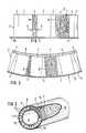
- an insulating mat 1 according to the invention comprises a support ply 2 having for example the shape of an aluminum lattice sheet and an insulating layer 3 which is fixed thereto, for example by gluing.
- the insulating layer 3 has mutually parallel strips 4 placed one beside the other, called lamelliform strips which are slightly compressible under the effect of a load in the direction of arrow 5.
- the strips 4 have a relatively low compressive strength, for example 3 kN per m2 and are arranged in such a way that the main orientation of the mineral fibers 6 is perpendicular to the plane of the support ply 2.
- the compressibility of the bands 4 allows, under the effect of a load exerted in the direction of arrow 5, good convex flexibility for the support ply 2 arranged at outside. Since the strips 4 are permanently connected, for example by gluing, to the support ply 2 made of a non-elastic substance, their width is fixed on the side of the support ply 2. When the insulating mat 1 is bent, the mineral fibers 6 can be compressed more perpendicular to the direction of their main orientation, on the side opposite to the support ply 2, so that the strips 4 become wedge-shaped and can have a width much less than their width on the side of the support ply 2. This is the functional principle of so-called conventional slats.
- the strips 4 are not immediately placed one beside the other to form the insulating layer 3 together, but support ribs 7 are inserted between them which usually replace the strips 4 provided at these locations.
- the support ribs 7 are made of rock fibers with a compressive strength of 30 kN per m2, the main orientation of the rock fibers 8 also being perpendicular to the plane of the support ply 2. The significantly higher compressive strength of the support ribs 7 gives them the consistency of a rigid plate.
- the apparent density necessary to achieve this resistance to compression and the content of corresponding binding agent are not too high when the main orientation of the fibers is that of the compressive load, so that the rock fibers 8 are mainly used in buckling.
- the compressive strength, parallel to the plane of the support ply 2 is significantly lower, but not to the point of allowing significant compression of the material constituting the support ribs 7 in the case of a bending of the insulating mat 1.
- Far from being a defect such compression or reduction of the width of the side of the support ribs 7 opposite to the support ply 2 would moreover in principle be desirable, but in fact very difficult to achieve, taking into account the priority given to the resistance to the compression.
- alternating relatively thin strips 4 with support ribs 7 also relatively thin.
- the width of the strips 4 is approximately 10 mm (measured when the strips 4 are not loaded as in FIG. 1) and that of the support ribs 7 30 mm for a insulating layer height 3 of approximately 50 mm.
- the insulation can be applied without difficulty according to a minimum radius of curvature of approximately 300 mm.
- the maximum insulation thickness is 43 mm if a mat 1 according to the invention is used whose ratio "v" is 40 / 35.
- the insulating mat 1 according to the invention can be used in all known applications of lamellar mats. However, it is preferably suitable for fields of application in which its greater compressive strength is required.
- the insulating mat 1 is suitable for cases where the primary requirement is not the heat-insulating power, but the compressive strength. In such cases, the insulating mat 1 can replace a mechanical support element, its insulating power totally excluding the risk of formation of thermal bridges.
- FIG. 3 Such an example of application is illustrated in FIG. 3.
- the wall of the body to be insulated, indicated at 9 in FIG. 2, is here that of a central pipe surrounded by an outer casing 10 made of sheet metal.
- an insulating material 12 has been placed, here son of the mats.
- the space 11 is protected by means of a support device 13, because the wire mats have a relatively low resistance to compression.
- the usual metal or ceramic supports are here replaced by an element formed by the insulating mat 1.
- the insulating mat 1 is placed around the central pipe, at the place where it is desired to place a support 13, the sheet metal envelope 10 resting on the outer face of the support ply 2.
- the support device 13 thus formed is extremely advantageous from the economic point of view and is more preferable to all the usual solid supports because of its insulating power. Thanks to the good load distribution of the compressive forces provided by the rigid outer casing 10, it is not necessary to provide a finely cross-linked distribution of thin support ribs 7. It is thus possible to use strips 4 of the usual width - for example, of the order of 50 mm or more - and support ribs 7 of corresponding width.
- an insulating mat 21 can also be used, as shown in FIG. 4, to form a support device 23 in all cases where it is necessary to maintain ventilation around an insulation 22 already in place and giving satisfaction from the point of view of its resistance to compression - for example of the shell type.
- the insulating mat 21 can then be produced in a smaller thickness and be arranged on the outer face of the insulation 22 and the inner face of the outer casing 10.
- the low insulation thickness of the insulating mat 21 here allows good flexibility with particularly small radii of curvature and therefore use on very thin pipes or on relatively sharp edges.
- the very consistency of the mat 21 is sufficient to meet most of the axial air permeability requirements, this in particular thanks to the presence of a lighter material which has a certain air permeability in the region of the strips 4 in the vicinity of the support ply 2.
- a closed annular insulating mat 21 or insulating mat 1 of the previous embodiment example
- segments of the insulating mat 1 or 21 can be secured, for example by gluing, so that these elements of the insulating mat 1 or 21 are distributed over the periphery of the wall 9 or of the insulation 22 as pressure shims.
- the support ribs 7 When the mat 1 of FIG. 2 is essentially used as insulation - and replaces an insulating shell - the support ribs 7 generally have a compressive strength of 10 to 50 kN per m2, preferably 30 kN per m2 and give in the case of a corresponding distribution and a corresponding proportion over the whole of the insulating layer 3, a compressive strength of the insulating mat 1 which is generally sufficient for good thermal insulation.
- one or more strips of the insulating mat 1 of an adequate width can be used, which makes it possible to achieve sufficient compressive strength thanks to the corresponding support width.
- support ribs of higher compressive strength of up to 100 kN per m2 and more.
- the compressive forces exerted on the surface of the insulating mat 21 are transmitted more regularly, for example, by virtue of a corresponding rigid structure of the outer casing 10, it is possible to forgo more and more of a distribution.
- the bands 4 or the support ribs 7 can be made not in one piece but of several strip or rib elements juxtaposed, each element being able to have the same width. It is also possible to combine elements to give bands 4 and support ribs 7 of different widths.
- the strips 4 can be formed by other mineral fibers than glass fibers.
- the support ribs 7 are not necessarily made of rock wool, or even necessarily of mineral fibers, because in principle any support material suitable having properties suitable for the intended application is suitable.
- the insulating mats 1 or 21 or small sections of any size thereof can be used as flexible bodies supporting a compression load in the form wedges or bands or plies or the like and as spacers that can be loaded in compression, these mats then offering, compared to elements used up to now, better heat-insulating power and possibly better fire resistance as well as better adaptability to the contours of the support surfaces.
Landscapes
- General Engineering & Computer Science (AREA)
- Engineering & Computer Science (AREA)
- Mechanical Engineering (AREA)
- Thermal Insulation (AREA)
- Laminated Bodies (AREA)
- Investigating Or Analysing Materials By The Use Of Chemical Reactions (AREA)
- Passenger Equipment (AREA)
- Push-Button Switches (AREA)
- Measurement Of The Respiration, Hearing Ability, Form, And Blood Characteristics Of Living Organisms (AREA)
- Insulating Bodies (AREA)
- Paper (AREA)
- Agricultural Chemicals And Associated Chemicals (AREA)
- Steering Controls (AREA)
- Footwear And Its Accessory, Manufacturing Method And Apparatuses (AREA)
- Moulding By Coating Moulds (AREA)
- Building Environments (AREA)
- Nonwoven Fabrics (AREA)
- Rigid Pipes And Flexible Pipes (AREA)
- Shaping Of Tube Ends By Bending Or Straightening (AREA)
Priority Applications (1)
| Application Number | Priority Date | Filing Date | Title |
|---|---|---|---|
| AT89400415T ATE72029T1 (de) | 1988-02-19 | 1989-02-15 | Isoliermatte fuer gekruemmte koerper, insbesonere fuer rohre sowie verwendung. |
Applications Claiming Priority (2)
| Application Number | Priority Date | Filing Date | Title |
|---|---|---|---|
| DE3805269 | 1988-02-19 | ||
| DE3805269A DE3805269A1 (de) | 1988-02-19 | 1988-02-19 | Daemmatte fuer koerper mit wenigstens bereichsweise gekruemmter oberflaeche, insbesondere fuer rohre, sowie ihre verwendung |
Publications (3)
| Publication Number | Publication Date |
|---|---|
| EP0329549A1 true EP0329549A1 (de) | 1989-08-23 |
| EP0329549B1 EP0329549B1 (de) | 1992-01-22 |
| EP0329549B2 EP0329549B2 (de) | 1994-11-02 |
Family
ID=6347773
Family Applications (1)
| Application Number | Title | Priority Date | Filing Date |
|---|---|---|---|
| EP89400415A Expired - Lifetime EP0329549B2 (de) | 1988-02-19 | 1989-02-15 | Isoliermatte für gekrümmte Körper, insbesonere für Rohre sowie Verwendung |
Country Status (17)
| Country | Link |
|---|---|
| US (1) | US5056564A (de) |
| EP (1) | EP0329549B2 (de) |
| JP (1) | JPH028597A (de) |
| KR (1) | KR890013407A (de) |
| AT (1) | ATE72029T1 (de) |
| AU (1) | AU612235B2 (de) |
| BR (1) | BR8900704A (de) |
| CA (1) | CA1333054C (de) |
| DE (2) | DE3805269A1 (de) |
| DK (1) | DK73089A (de) |
| ES (1) | ES2030280T5 (de) |
| FI (1) | FI93899C (de) |
| IE (1) | IE61780B1 (de) |
| NO (1) | NO176629C (de) |
| NZ (1) | NZ228029A (de) |
| PT (1) | PT89762B (de) |
| TR (1) | TR26730A (de) |
Cited By (3)
| Publication number | Priority date | Publication date | Assignee | Title |
|---|---|---|---|---|
| EP0457787B2 (de) † | 1989-02-13 | 2000-07-26 | Soltech, Inc. | Wärmedämpfungsmantel |
| EP1046848A1 (de) * | 1999-04-23 | 2000-10-25 | Aeroflex International Co., Ltd. | Isolierelement für Rohre |
| EP3534053B1 (de) | 2018-03-02 | 2023-05-17 | Knauf Insulation SPRL | Isolierte rohr-ähnliche anordnung und verfahren zum isolieren einer rohr-ähnlichen anordnung |
Families Citing this family (21)
| Publication number | Priority date | Publication date | Assignee | Title |
|---|---|---|---|---|
| DE3928018A1 (de) * | 1989-08-24 | 1991-02-28 | Gruenzweig & Hartmann | Verfahren zur herstellung eines flaechenelementes zur absorption von elektromagnetischen wellen |
| US5318076A (en) * | 1992-11-13 | 1994-06-07 | Bloom Engineering Company, Inc. | Protective refractory locking mechanism |
| US5393105A (en) * | 1992-12-24 | 1995-02-28 | Petterson; Bart | Ductwork for delivery of low temperature air |
| US5437312A (en) * | 1993-01-27 | 1995-08-01 | Performance Contracting, Inc. | Reinforced insulation blanket |
| GB9509848D0 (en) * | 1995-05-16 | 1995-07-12 | Darchem Eng Ltd | Fire protective system |
| PL179755B1 (pl) * | 1995-05-22 | 2000-10-31 | Rockwool Int | Sposób izolowania rury PL PL PL PL PL |
| DE19615903C2 (de) * | 1996-04-22 | 2003-05-08 | Fritz Homann Gmbh & Co Kg | Wärmedämmelement |
| FR2780135B1 (fr) | 1998-06-18 | 2000-08-25 | Philec Sa | Protection thermique formant bouclier thermique |
| FR2785968B1 (fr) * | 1998-11-16 | 2001-01-12 | Inst Francais Du Petrole | Conduite isolee thermiquement par un materiau elastomere et methode de fabrication |
| US6116290A (en) * | 1999-03-16 | 2000-09-12 | J. Ray Mcdermott, S.A. | Internally insulated, corrosion resistant pipeline |
| RU2226642C2 (ru) * | 2002-03-25 | 2004-04-10 | Федеральное государственное унитарное предприятие "Центральный научно-исследовательский институт им. акад. А.Н. Крылова" | Теплоизолирующее покрытие горизонтального трубопровода |
| DE10317937A1 (de) * | 2003-04-17 | 2004-11-04 | Saint-Gobain Isover G+H Ag | Verfahren zur Herstellung von Rohrschalen aus Mineralwolle sowie derartige Rohrschalen |
| RU2233400C1 (ru) * | 2003-09-08 | 2004-07-27 | Баранников Андрей Альбертович | Листовой теплоизолирующий материал |
| DE202004010026U1 (de) * | 2004-06-25 | 2004-10-21 | Deutsche Rockwool Mineralwoll Gmbh + Co Ohg | Rohrisolierungselement zur Wärme- und/oder Schalldämmung einer Rohrleitung |
| US7628611B2 (en) * | 2005-07-29 | 2009-12-08 | Bloom Engineering Company, Inc. | Low conductivity refractory insulation member with fiber mat |
| NO328288B1 (no) * | 2007-11-20 | 2010-01-25 | Mittet As | Fremgangsmåte for fremstilling av isolasjonsmateriale samt anvendelse av dette |
| DE102009015590A1 (de) * | 2009-03-30 | 2010-10-07 | Airbus Deutschland Gmbh | Luftfahrzeug mit einem Isolierungssystem zur Wärme- und Schallisolierung |
| US10458833B2 (en) | 2014-05-16 | 2019-10-29 | Sorin Group Italia S.R.L. | Blood reservoir with fluid volume measurement based on pressure sensor |
| RU190528U1 (ru) * | 2018-12-19 | 2019-07-03 | Дмитрий Иванович Тразанов | Теплоизоляционное изделие |
| CN111120783B (zh) * | 2020-03-13 | 2024-12-27 | 江苏龙英管道新材料有限公司 | 一种能够减少热损和管托摩擦的热网系统 |
| CN111981251B (zh) * | 2020-08-25 | 2021-11-16 | 六安中财管道科技有限公司 | 一种保温一体太阳能专用管材及加工工艺 |
Citations (3)
| Publication number | Priority date | Publication date | Assignee | Title |
|---|---|---|---|---|
| FR1069988A (fr) * | 1953-01-21 | 1954-07-15 | Barbier & Cie G | éléments de calorifugeage |
| FR1256923A (fr) * | 1960-05-13 | 1961-03-24 | Isolant pour tuyaux et procédé pour sa fabrication | |
| US4025680A (en) * | 1976-03-05 | 1977-05-24 | Johns-Manville Corporation | Curvable fibrous thermal insulation |
Family Cites Families (15)
| Publication number | Priority date | Publication date | Assignee | Title |
|---|---|---|---|---|
| US1661254A (en) * | 1926-01-25 | 1928-03-06 | Union Asbestos & Rubber Co | Pipe covering |
| US1907307A (en) * | 1930-05-06 | 1933-05-02 | Coast Insulating Co | Pipe covering |
| US2949953A (en) * | 1955-05-26 | 1960-08-23 | Maio Vincent Di | Pipe insulator and method of making same |
| US3012923A (en) * | 1957-09-30 | 1961-12-12 | Owens Corning Fiberglass Corp | Fibrous products and method and apparatus for producing same |
| US3117902A (en) * | 1958-10-20 | 1964-01-14 | Fastab Insulations Inc | Insulating coverings for enclosures |
| GB1235776A (en) * | 1969-04-16 | 1971-06-16 | Newalls Insulation And Chemica | Insulation |
| BE789716A (fr) * | 1971-10-05 | 1973-02-01 | Rockwool As | Panneaux isolants et leur fabrication |
| JPS6028868Y2 (ja) * | 1976-11-08 | 1985-09-02 | 工業技術院長 | 高温ガス流通管 |
| GB1554330A (en) * | 1977-01-21 | 1979-10-17 | Ph Thermal Prod Ltd | Thermal pipe insulation |
| FI66478C (fi) * | 1981-07-06 | 1984-10-10 | Partek Ab | Roerskaolelement och saett att framstaella detsamma |
| DE3346230A1 (de) * | 1983-12-21 | 1985-07-11 | INTERATOM GmbH, 5060 Bergisch Gladbach | Heissgasbehaelter mit isolierung aus einander ueberlappenden keramischen koerpern |
| DE3531751A1 (de) * | 1985-09-05 | 1987-03-05 | Interatom | Flaechig vorgespannte isolierung fuer heissgasleitungen und -behaelter |
| US4823845A (en) * | 1987-09-04 | 1989-04-25 | Manville Corporation | Pipe insulation |
| US4878459A (en) * | 1989-02-13 | 1989-11-07 | Nelson Thomas E | Water heater construction |
| US4972759A (en) * | 1989-02-13 | 1990-11-27 | Nelson Thomas E | Thermal insulation jacket |
-
1988
- 1988-02-19 DE DE3805269A patent/DE3805269A1/de active Granted
-
1989
- 1989-02-14 TR TR89/0152A patent/TR26730A/xx unknown
- 1989-02-15 AU AU29966/89A patent/AU612235B2/en not_active Ceased
- 1989-02-15 ES ES89400415T patent/ES2030280T5/es not_active Expired - Lifetime
- 1989-02-15 EP EP89400415A patent/EP0329549B2/de not_active Expired - Lifetime
- 1989-02-15 DE DE8989400415T patent/DE68900729D1/de not_active Expired - Fee Related
- 1989-02-15 IE IE47789A patent/IE61780B1/en not_active IP Right Cessation
- 1989-02-15 AT AT89400415T patent/ATE72029T1/de not_active IP Right Cessation
- 1989-02-17 FI FI890797A patent/FI93899C/fi not_active IP Right Cessation
- 1989-02-17 DK DK073089A patent/DK73089A/da not_active Application Discontinuation
- 1989-02-17 NO NO890693A patent/NO176629C/no unknown
- 1989-02-17 NZ NZ228029A patent/NZ228029A/xx unknown
- 1989-02-17 BR BR898900704A patent/BR8900704A/pt not_active IP Right Cessation
- 1989-02-17 CA CA000591316A patent/CA1333054C/fr not_active Expired - Fee Related
- 1989-02-17 PT PT89762A patent/PT89762B/pt not_active IP Right Cessation
- 1989-02-18 KR KR1019890001900A patent/KR890013407A/ko not_active Ceased
- 1989-02-20 JP JP1038509A patent/JPH028597A/ja active Pending
- 1989-02-21 US US07/312,494 patent/US5056564A/en not_active Expired - Fee Related
Patent Citations (3)
| Publication number | Priority date | Publication date | Assignee | Title |
|---|---|---|---|---|
| FR1069988A (fr) * | 1953-01-21 | 1954-07-15 | Barbier & Cie G | éléments de calorifugeage |
| FR1256923A (fr) * | 1960-05-13 | 1961-03-24 | Isolant pour tuyaux et procédé pour sa fabrication | |
| US4025680A (en) * | 1976-03-05 | 1977-05-24 | Johns-Manville Corporation | Curvable fibrous thermal insulation |
Cited By (4)
| Publication number | Priority date | Publication date | Assignee | Title |
|---|---|---|---|---|
| EP0457787B2 (de) † | 1989-02-13 | 2000-07-26 | Soltech, Inc. | Wärmedämpfungsmantel |
| EP1046848A1 (de) * | 1999-04-23 | 2000-10-25 | Aeroflex International Co., Ltd. | Isolierelement für Rohre |
| US6318681B1 (en) | 1999-04-23 | 2001-11-20 | Aeroflex International Co. Ltd. | Insulating element for pipes |
| EP3534053B1 (de) | 2018-03-02 | 2023-05-17 | Knauf Insulation SPRL | Isolierte rohr-ähnliche anordnung und verfahren zum isolieren einer rohr-ähnlichen anordnung |
Also Published As
| Publication number | Publication date |
|---|---|
| IE890477L (en) | 1989-08-19 |
| US5056564A (en) | 1991-10-15 |
| DK73089A (da) | 1989-08-20 |
| EP0329549B1 (de) | 1992-01-22 |
| PT89762A (pt) | 1989-10-04 |
| ATE72029T1 (de) | 1992-02-15 |
| FI93899B (fi) | 1995-02-28 |
| FI93899C (fi) | 1995-06-12 |
| NZ228029A (en) | 1991-01-29 |
| FI890797A0 (fi) | 1989-02-17 |
| ES2030280T3 (es) | 1992-10-16 |
| NO890693L (no) | 1989-08-21 |
| NO176629C (no) | 1995-05-03 |
| AU2996689A (en) | 1989-08-24 |
| BR8900704A (pt) | 1989-10-17 |
| CA1333054C (fr) | 1994-11-15 |
| JPH028597A (ja) | 1990-01-12 |
| IE61780B1 (en) | 1994-11-30 |
| EP0329549B2 (de) | 1994-11-02 |
| ES2030280T5 (es) | 1995-08-16 |
| DE68900729D1 (de) | 1992-03-05 |
| FI890797L (fi) | 1989-08-20 |
| AU612235B2 (en) | 1991-07-04 |
| DE3805269C2 (de) | 1992-02-27 |
| NO176629B (no) | 1995-01-23 |
| NO890693D0 (no) | 1989-02-17 |
| DE3805269A1 (de) | 1989-08-31 |
| KR890013407A (ko) | 1989-09-23 |
| TR26730A (tr) | 1994-07-06 |
| DK73089D0 (da) | 1989-02-17 |
| PT89762B (pt) | 1996-02-29 |
Similar Documents
| Publication | Publication Date | Title |
|---|---|---|
| EP0329549B1 (de) | Isoliermatte für gekrümmte Körper, insbesonere für Rohre sowie Verwendung | |
| EP0877887B1 (de) | Biegsame rohrleitung mit einem gasdichten innenwellenrohr aus metall | |
| EP2959199B1 (de) | Flexibles rohr zum transport von kohlenwasserstoffen mit einer äusseren verstärkten versiegelten hülle | |
| EP0890056B1 (de) | Leitungsrohr des typs doppelwärmedämpfungsmantel | |
| EP3224393B1 (de) | Wärmedämmschicht für eine flexible unterwasserrohrleitung | |
| CA2064196C (fr) | Conduite tubulaire flexible comportant des moyens de chauffage incorpores | |
| EP0060856B1 (de) | Verfahren zum verstärken eines hohlkörpers durch wickeln eines formstückes, formstück für seine durchführung und hergestellte verstärkte kanalisation | |
| EP0109896B1 (de) | Elektromagnetische Lagereinrichtung für hohe Temperaturen | |
| FR2744511A1 (fr) | Conduite flexible a fluage limite de la gaine d'etancheite interne dans des armures | |
| EP1608904A1 (de) | Flexible rohrleitung zum transport eines fluids | |
| FR2527845A1 (fr) | Isolant thermique, en particulier pour batterie d'accumulateurs | |
| FR2529007A1 (fr) | Cable electrique supportant des conditions d'emploi tres severes | |
| EP1179157B1 (de) | Thermisch isoliertes rohr für den transport von flüssigkeiten | |
| FR2505057A1 (fr) | Element porteur non metallique pour cable et cable comportant un tel porteur | |
| EP0140773B1 (de) | Schlauch, insbesondere für den Transport von Flüssigkeiten mit unterschiedlichem Temperaturniveau | |
| WO1998034061A1 (fr) | Enveloppe d'isolation thermique, notamment pour la construction de canalisations sous-marines vehiculant des produits petroliers | |
| FR2463487A1 (fr) | Enveloppe tubulaire souple resistant a de fortes pressions et a des efforts de traction eleves | |
| EP1561061B1 (de) | Flexible röhrenförmige leitung zum fluidtransport | |
| EP0234156B1 (de) | Rohrförmiges Gefüge, welches ein gefaltetes Flachband enthält | |
| FR2588595A1 (fr) | Element tubulaire prefabrique, notamment pour cheminees | |
| EP0165471A1 (de) | Zugfeste Bewehrung für Kabel und Kabel zur Anwendung unter Wasser mit einer ähnlichen Bewehrung versehen | |
| EP0340123A1 (de) | Isoliertes Rohrelement zur Errichtung von oberirdischen Flüssigkeitstransporteinrichtungen, Verfahren zur Errichtung sowie Einrichtungen aus solchen Elementen | |
| FR2507230A1 (fr) | Profil metallique longitudinal et installation du circuit absorbeur de pompe a chaleur | |
| LU83182A1 (fr) | Procede et dispositif de compensation des mouvements d'allongement d'une canalisation | |
| FR2509422A1 (fr) | Bague elastique destinee a l'isolation des conduites de fluide thermique |
Legal Events
| Date | Code | Title | Description |
|---|---|---|---|
| PUAI | Public reference made under article 153(3) epc to a published international application that has entered the european phase |
Free format text: ORIGINAL CODE: 0009012 |
|
| AK | Designated contracting states |
Kind code of ref document: A1 Designated state(s): AT BE CH DE ES FR GB IT LI LU NL SE |
|
| 16A | New documents despatched to applicant after publication of the search report | ||
| 17P | Request for examination filed |
Effective date: 19900129 |
|
| 17Q | First examination report despatched |
Effective date: 19901214 |
|
| GRAA | (expected) grant |
Free format text: ORIGINAL CODE: 0009210 |
|
| AK | Designated contracting states |
Kind code of ref document: B1 Designated state(s): AT BE CH DE ES FR GB IT LI LU NL SE |
|
| REF | Corresponds to: |
Ref document number: 72029 Country of ref document: AT Date of ref document: 19920215 Kind code of ref document: T |
|
| REF | Corresponds to: |
Ref document number: 68900729 Country of ref document: DE Date of ref document: 19920305 |
|
| ITF | It: translation for a ep patent filed | ||
| GBT | Gb: translation of ep patent filed (gb section 77(6)(a)/1977) | ||
| PLBI | Opposition filed |
Free format text: ORIGINAL CODE: 0009260 |
|
| 26 | Opposition filed |
Opponent name: DEUTSCHE ROCKWOOL MINERALWOLL-GMBH Effective date: 19921020 |
|
| NLR1 | Nl: opposition has been filed with the epo |
Opponent name: DEUTSCHE ROCKWOOL MINERALWOLL-GMBH |
|
| PGFP | Annual fee paid to national office [announced via postgrant information from national office to epo] |
Ref country code: FR Payment date: 19940121 Year of fee payment: 6 |
|
| PGFP | Annual fee paid to national office [announced via postgrant information from national office to epo] |
Ref country code: BE Payment date: 19940127 Year of fee payment: 6 |
|
| PGFP | Annual fee paid to national office [announced via postgrant information from national office to epo] |
Ref country code: LU Payment date: 19940331 Year of fee payment: 6 |
|
| EPTA | Lu: last paid annual fee | ||
| PUAH | Patent maintained in amended form |
Free format text: ORIGINAL CODE: 0009272 |
|
| STAA | Information on the status of an ep patent application or granted ep patent |
Free format text: STATUS: PATENT MAINTAINED AS AMENDED |
|
| 27A | Patent maintained in amended form |
Effective date: 19941102 |
|
| AK | Designated contracting states |
Kind code of ref document: B2 Designated state(s): AT BE CH DE ES FR GB IT LI LU NL SE |
|
| REG | Reference to a national code |
Ref country code: CH Ref legal event code: AEN |
|
| NLR2 | Nl: decision of opposition | ||
| EAL | Se: european patent in force in sweden |
Ref document number: 89400415.9 |
|
| ITF | It: translation for a ep patent filed | ||
| PGFP | Annual fee paid to national office [announced via postgrant information from national office to epo] |
Ref country code: ES Payment date: 19950206 Year of fee payment: 7 |
|
| PG25 | Lapsed in a contracting state [announced via postgrant information from national office to epo] |
Ref country code: LU Free format text: LAPSE BECAUSE OF NON-PAYMENT OF DUE FEES Effective date: 19950215 |
|
| PG25 | Lapsed in a contracting state [announced via postgrant information from national office to epo] |
Ref country code: BE Effective date: 19950228 |
|
| NLR3 | Nl: receipt of modified translations in the netherlands language after an opposition procedure | ||
| GBTA | Gb: translation of amended ep patent filed (gb section 77(6)(b)/1977) |
Effective date: 19950222 |
|
| REG | Reference to a national code |
Ref country code: ES Ref legal event code: DC2A Kind code of ref document: T5 Effective date: 19950816 |
|
| BERE | Be: lapsed |
Owner name: ISOVER SAINT-GOBAIN Effective date: 19950228 |
|
| PG25 | Lapsed in a contracting state [announced via postgrant information from national office to epo] |
Ref country code: FR Effective date: 19951031 |
|
| REG | Reference to a national code |
Ref country code: FR Ref legal event code: ST |
|
| PGFP | Annual fee paid to national office [announced via postgrant information from national office to epo] |
Ref country code: SE Payment date: 19960117 Year of fee payment: 8 |
|
| PGFP | Annual fee paid to national office [announced via postgrant information from national office to epo] |
Ref country code: AT Payment date: 19960125 Year of fee payment: 8 |
|
| PGFP | Annual fee paid to national office [announced via postgrant information from national office to epo] |
Ref country code: GB Payment date: 19960220 Year of fee payment: 8 |
|
| PGFP | Annual fee paid to national office [announced via postgrant information from national office to epo] |
Ref country code: NL Payment date: 19960223 Year of fee payment: 8 |
|
| PGFP | Annual fee paid to national office [announced via postgrant information from national office to epo] |
Ref country code: CH Payment date: 19960227 Year of fee payment: 8 |
|
| PGFP | Annual fee paid to national office [announced via postgrant information from national office to epo] |
Ref country code: DE Payment date: 19960301 Year of fee payment: 8 |
|
| PG25 | Lapsed in a contracting state [announced via postgrant information from national office to epo] |
Ref country code: GB Effective date: 19970215 Ref country code: AT Effective date: 19970215 |
|
| PG25 | Lapsed in a contracting state [announced via postgrant information from national office to epo] |
Ref country code: SE Effective date: 19970216 |
|
| PG25 | Lapsed in a contracting state [announced via postgrant information from national office to epo] |
Ref country code: ES Free format text: LAPSE BECAUSE OF NON-PAYMENT OF DUE FEES Effective date: 19970217 |
|
| PG25 | Lapsed in a contracting state [announced via postgrant information from national office to epo] |
Ref country code: LI Effective date: 19970228 Ref country code: CH Effective date: 19970228 |
|
| PG25 | Lapsed in a contracting state [announced via postgrant information from national office to epo] |
Ref country code: NL Effective date: 19970901 |
|
| GBPC | Gb: european patent ceased through non-payment of renewal fee |
Effective date: 19970215 |
|
| REG | Reference to a national code |
Ref country code: CH Ref legal event code: PL |
|
| PG25 | Lapsed in a contracting state [announced via postgrant information from national office to epo] |
Ref country code: DE Effective date: 19971101 |
|
| EUG | Se: european patent has lapsed |
Ref document number: 89400415.9 |
|
| NLV4 | Nl: lapsed or anulled due to non-payment of the annual fee |
Effective date: 19970901 |
|
| REG | Reference to a national code |
Ref country code: ES Ref legal event code: FD2A Effective date: 19990503 |
|
| PG25 | Lapsed in a contracting state [announced via postgrant information from national office to epo] |
Ref country code: IT Free format text: LAPSE BECAUSE OF NON-PAYMENT OF DUE FEES;WARNING: LAPSES OF ITALIAN PATENTS WITH EFFECTIVE DATE BEFORE 2007 MAY HAVE OCCURRED AT ANY TIME BEFORE 2007. THE CORRECT EFFECTIVE DATE MAY BE DIFFERENT FROM THE ONE RECORDED. Effective date: 20050215 |