EP0329624A2 - Outil de coupe rotatif - Google Patents
Outil de coupe rotatif Download PDFInfo
- Publication number
- EP0329624A2 EP0329624A2 EP89830053A EP89830053A EP0329624A2 EP 0329624 A2 EP0329624 A2 EP 0329624A2 EP 89830053 A EP89830053 A EP 89830053A EP 89830053 A EP89830053 A EP 89830053A EP 0329624 A2 EP0329624 A2 EP 0329624A2
- Authority
- EP
- European Patent Office
- Prior art keywords
- cutting
- helical
- tooth
- sectors
- edge section
- Prior art date
- Legal status (The legal status is an assumption and is not a legal conclusion. Google has not performed a legal analysis and makes no representation as to the accuracy of the status listed.)
- Withdrawn
Links
- 230000002093 peripheral effect Effects 0.000 claims description 6
- 238000007599 discharging Methods 0.000 claims description 3
- 230000015572 biosynthetic process Effects 0.000 description 2
- 238000003801 milling Methods 0.000 description 2
- 238000004519 manufacturing process Methods 0.000 description 1
- 238000009827 uniform distribution Methods 0.000 description 1
Images

Classifications
-
- B—PERFORMING OPERATIONS; TRANSPORTING
- B23—MACHINE TOOLS; METAL-WORKING NOT OTHERWISE PROVIDED FOR
- B23C—MILLING
- B23C5/00—Milling-cutters
- B23C5/02—Milling-cutters characterised by the shape of the cutter
- B23C5/10—Shank-type cutters, i.e. with an integral shaft
-
- B—PERFORMING OPERATIONS; TRANSPORTING
- B23—MACHINE TOOLS; METAL-WORKING NOT OTHERWISE PROVIDED FOR
- B23C—MILLING
- B23C2210/00—Details of milling cutters
- B23C2210/08—Side or top views of the cutting edge
- B23C2210/088—Cutting edges with a wave form
-
- B—PERFORMING OPERATIONS; TRANSPORTING
- B23—MACHINE TOOLS; METAL-WORKING NOT OTHERWISE PROVIDED FOR
- B23C—MILLING
- B23C2220/00—Details of milling processes
- B23C2220/60—Roughing
- B23C2220/605—Roughing and finishing
Definitions
- the present invention relates to a rotary cutting tool, particularly a cylindrical end mill of the type comprising an elongate body with an attachment portion and a cutting portion, in which the cutting portion has a plurality of helical grooves defining between them a corresponding plurality of helical teeth each having a peripheral surface, a cutting edge, a face, a groove for discharging the chips, and a back.
- the object of the invention is to produce a rotary cutting tool which enables an improved milling rate to be achieved whilst maintaining good finishing characteristics, particularly by enabling rough-milling and finishing in a single pass.
- each tooth is constituted by a plurality of adjacent cutting sectors each of which has a helical cutting-edge section and a connecting section which extends in an axial plane, the helical cutting-edge section having a helix angle larger than the ideal theoretical helix angle characterising the helical shape of each tooth.
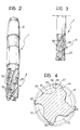
- a cylindrical end mill is constituted by an elongate body having an attachment shank 2 and a portion 4 with cutting surfaces formed from a cylindrical or possibly conical body.
- the cylindrical end mill has four helical grooves, indicated 6, 8, 10 and 12, which define four helical teeth 14, 16, 18 and 20.
- Each tooth has a peripheral surface 22 and a face 26 the intersection of which defines a cutting edge 24, a groove 28 for discharging the chips, and a back 30.
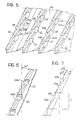
- each tooth is constituted by a plurality of successive cutting sectors T ( Figure 7) each of which has a helical cutting-edge section 24a and a connecting section 24b which extends in an axial plane.
- the helix angle of the helical cutting-edge section 24a is indicated AE and may be defined as the effective helix angle of the cutting edge.
- the angle AE is larger than the theoretical helix angle AT which characterises the helical shape of each tooth.
- the angle AT may be defined as the angle of the helix which passes through the points of intersection between each helical cutting-edge section 24a and the section 24b.
- the size of the angle AE depends on the material which the mill is intended to work and is generally between 10 and 45° .
- the cutting sectors are geometrically and dimensionally identical to each other, but the cutting sectors of each tooth are offset axially from the cutting sectors of the adjacent tooth. This arrangement ensures the uniform distribution of the cutting forces.
- the section 24b of the cutting edge is substantially rectilinear and extends axially.
- the peripheral surface 22 has a notch 32 in correspondence with each connecting section 24b.
- the surface of each tooth has a sharp surface portion 22a defined by the cutting edge 24a adjacent the surface 22.
- the surface of each tooth is also made up of chip-breaking surfaces 28 which are associated with each cutting sector and cause the formation and expulsion of the chips.
- the surfaces of the notches 32 are offset from each other and preferably arranged on a helix, preferably a left-handed helix.
- the required number of teeth, the pitch of the theoretical helix angle, the pitch of the effective angle, and the length of each cutting sector must be predetermined. This data enables the value of the offset between one tooth and another, and the lengths of the helical and axial parts of each cutting sector to be determined.
- a conventional disc-shaped tool is used to produce the grooves.
- the inclination of the side of this tool to the axis of the mill is initially set at a value equal to the effective helix angle AE.
- the removal is thus started on the effective helix and continues through the length of the helical part of the sector, followed by the axial connecting part. This operation is repeated through the length of each groove.
- the mill under manufacture After returning to the starting position, the mill under manufacture is rotated counterclockwise by the angle necessary for the formation of the second tooth. The removal is then continued on the theoretical helix for a distance equal to the offset of the sectors, after which the same sequence as for the preceding tooth is repeated. After all the teeth have been completed, the peripheral notches 32 are formed in the cutting edges. The diametral sharpening is carried out conventionally.
- the cylindrical end mill according to the invention has the faces of its teeth sharpened to achieve improved cutting edges, and its shape enables the resharpening of the faces of the teeth, as well as conventional diametral resharpening.
Landscapes
- Engineering & Computer Science (AREA)
- Mechanical Engineering (AREA)
- Milling Processes (AREA)
Applications Claiming Priority (2)
| Application Number | Priority Date | Filing Date | Title |
|---|---|---|---|
| IT67129/88A IT1219034B (it) | 1988-02-19 | 1988-02-19 | Utensile da taglio rotante |
| IT6712988 | 1988-02-19 |
Publications (2)
| Publication Number | Publication Date |
|---|---|
| EP0329624A2 true EP0329624A2 (fr) | 1989-08-23 |
| EP0329624A3 EP0329624A3 (fr) | 1990-10-10 |
Family
ID=11299834
Family Applications (1)
| Application Number | Title | Priority Date | Filing Date |
|---|---|---|---|
| EP19890830053 Withdrawn EP0329624A3 (fr) | 1988-02-19 | 1989-02-14 | Outil de coupe rotatif |
Country Status (2)
| Country | Link |
|---|---|
| EP (1) | EP0329624A3 (fr) |
| IT (1) | IT1219034B (fr) |
Cited By (7)
| Publication number | Priority date | Publication date | Assignee | Title |
|---|---|---|---|---|
| FR2649341A1 (fr) * | 1989-07-07 | 1991-01-11 | Avyac Outillages Machines | Fraise sur champ avec aretes de coupe a angle variable |
| US6164876A (en) * | 1999-10-30 | 2000-12-26 | Tungsten Industries, Inc | Cutting tool |
| USD774573S1 (en) | 2014-04-10 | 2016-12-20 | Kennametal Inc | Cutting tool with W-shaped flute gully |
| US9724768B2 (en) | 2014-04-10 | 2017-08-08 | Kennametal Inc | Cutting tool with enhanced chip evacuation capability and method of making same |
| US9878379B2 (en) | 2015-04-22 | 2018-01-30 | Kennametal Inc. | Cutting tool with enhanced chip evacuation capability and method of making same |
| EP3708283A1 (fr) * | 2019-03-13 | 2020-09-16 | Seco Tools Ab | Outil de coupe, procédé de fabrication d'un outil de coupe et procédé d'usinage d'une pièce de travail |
| US20220072628A1 (en) * | 2018-12-28 | 2022-03-10 | Kyocera Sgs Precision Tools, Inc. | Gapless chipbreaker |
Families Citing this family (1)
| Publication number | Priority date | Publication date | Assignee | Title |
|---|---|---|---|---|
| CN119952124B (zh) * | 2025-03-12 | 2025-10-17 | 深圳市鑫运祥精密刀具有限公司 | 一种纤维材料加工用合金铣刀及合金铣刀的加工工艺 |
Family Cites Families (2)
| Publication number | Priority date | Publication date | Assignee | Title |
|---|---|---|---|---|
| US3775819A (en) * | 1972-12-14 | 1973-12-04 | Weldon Tool Co | Rotating cutting tool |
| US4560308A (en) * | 1984-08-13 | 1985-12-24 | Trw Inc. | Cutting tool |
-
1988
- 1988-02-19 IT IT67129/88A patent/IT1219034B/it active
-
1989
- 1989-02-14 EP EP19890830053 patent/EP0329624A3/fr not_active Withdrawn
Cited By (17)
| Publication number | Priority date | Publication date | Assignee | Title |
|---|---|---|---|---|
| FR2649341A1 (fr) * | 1989-07-07 | 1991-01-11 | Avyac Outillages Machines | Fraise sur champ avec aretes de coupe a angle variable |
| US6164876A (en) * | 1999-10-30 | 2000-12-26 | Tungsten Industries, Inc | Cutting tool |
| US10682712B2 (en) | 2014-04-10 | 2020-06-16 | Kennametal Inc. | Cutting tool with enhanced chip evacuation capability and method of making same |
| USD774573S1 (en) | 2014-04-10 | 2016-12-20 | Kennametal Inc | Cutting tool with W-shaped flute gully |
| USD792489S1 (en) | 2014-04-10 | 2017-07-18 | Kennametal Inc. | Cutting tool with w-shaped flute gully |
| USD793460S1 (en) | 2014-04-10 | 2017-08-01 | Kennametal Inc. | Cutting tool with w-shaped flute gully |
| US9724768B2 (en) | 2014-04-10 | 2017-08-08 | Kennametal Inc | Cutting tool with enhanced chip evacuation capability and method of making same |
| USD796563S1 (en) | 2014-04-10 | 2017-09-05 | Kennametal Inc. | Cutting tool with W-shaped flute gully |
| USD797170S1 (en) | 2014-04-10 | 2017-09-12 | Kennametal Inc. | Cutting tool with W-shaped flute gully |
| DE102015105216B4 (de) * | 2014-04-10 | 2019-08-08 | Hanita Metal Works Ltd. | Fräser mit verbesserter Spanabfuhrfähigkeit und Verfahren zu dessen Herstellung |
| US9878379B2 (en) | 2015-04-22 | 2018-01-30 | Kennametal Inc. | Cutting tool with enhanced chip evacuation capability and method of making same |
| US20220072628A1 (en) * | 2018-12-28 | 2022-03-10 | Kyocera Sgs Precision Tools, Inc. | Gapless chipbreaker |
| EP3708283A1 (fr) * | 2019-03-13 | 2020-09-16 | Seco Tools Ab | Outil de coupe, procédé de fabrication d'un outil de coupe et procédé d'usinage d'une pièce de travail |
| WO2020182534A1 (fr) * | 2019-03-13 | 2020-09-17 | Seco Tools Ab | Outil de coupe, procédé de fabrication d'outil de coupe et procédé d'usinage d'une pièce de fabrication |
| CN113557098A (zh) * | 2019-03-13 | 2021-10-26 | 山高刀具公司 | 切削刀具、制造切削刀具的方法和加工工件的方法 |
| US11890685B2 (en) | 2019-03-13 | 2024-02-06 | Seco Tools Ab | Cutting tool, a method for manufacturing a cutting tool and a method for machining of a workpiece |
| CN113557098B (zh) * | 2019-03-13 | 2024-02-23 | 山高刀具公司 | 切削刀具、制造切削刀具的方法和加工工件的方法 |
Also Published As
| Publication number | Publication date |
|---|---|
| EP0329624A3 (fr) | 1990-10-10 |
| IT1219034B (it) | 1990-04-24 |
| IT8867129A0 (it) | 1988-02-19 |
Similar Documents
| Publication | Publication Date | Title |
|---|---|---|
| US5272940A (en) | Helically fluted tool | |
| US4573838A (en) | Hole cutter | |
| US7223053B2 (en) | Helical flute end mill with multi-section cutting edge | |
| DE3727968C2 (de) | Schaftfräser mit Schneideinsätzen | |
| US4497600A (en) | End mill | |
| US9878379B2 (en) | Cutting tool with enhanced chip evacuation capability and method of making same | |
| DE3844787C2 (fr) | ||
| US3548476A (en) | Milling cutter construction | |
| EP0094921A1 (fr) | Plaquette de coupe | |
| DE3807195C2 (fr) | ||
| JPH0215328B2 (fr) | ||
| EP0796690A2 (fr) | Dispositif et méthode à usiner des rainures à chambrage | |
| JPH0117804B2 (fr) | ||
| CA1236955A (fr) | Dispositif de taille de filetages | |
| JPS60213407A (ja) | ルーター工具およびそのインサート | |
| US4770567A (en) | Roughing cutter | |
| US6565297B2 (en) | Method of milling large thread lengths | |
| US4219292A (en) | Rotary helical milling cutter with replaceable cutter bit elements | |
| US4645386A (en) | Thread-cutting apparatus | |
| JPS6125488B2 (fr) | ||
| EP1713607B1 (fr) | Outil de decoupe et partie d'outil a surfaces de connexions possedant des rainures et procede de fabrication d'une telle partie d'outil | |
| EP0566085B1 (fr) | Plaquette de coupe à fraiser | |
| EP2202020A1 (fr) | Outil universel et inserts pour le fraisage de cannelures et procédé de fraisage de cannelures | |
| JPH0435288B2 (fr) | ||
| US4536106A (en) | Heavy duty hob |
Legal Events
| Date | Code | Title | Description |
|---|---|---|---|
| PUAI | Public reference made under article 153(3) epc to a published international application that has entered the european phase |
Free format text: ORIGINAL CODE: 0009012 |
|
| AK | Designated contracting states |
Kind code of ref document: A2 Designated state(s): AT BE CH DE ES FR GB GR IT LI LU NL SE |
|
| PUAL | Search report despatched |
Free format text: ORIGINAL CODE: 0009013 |
|
| AK | Designated contracting states |
Kind code of ref document: A3 Designated state(s): AT BE CH DE ES FR GB GR IT LI LU NL SE |
|
| 17P | Request for examination filed |
Effective date: 19901129 |
|
| 17Q | First examination report despatched |
Effective date: 19920303 |
|
| STAA | Information on the status of an ep patent application or granted ep patent |
Free format text: STATUS: THE APPLICATION IS DEEMED TO BE WITHDRAWN |
|
| 18D | Application deemed to be withdrawn |
Effective date: 19930608 |