EP0329688B1 - Commutateur a pression differentielle a limitation de pression - Google Patents
Commutateur a pression differentielle a limitation de pression Download PDFInfo
- Publication number
- EP0329688B1 EP0329688B1 EP87907269A EP87907269A EP0329688B1 EP 0329688 B1 EP0329688 B1 EP 0329688B1 EP 87907269 A EP87907269 A EP 87907269A EP 87907269 A EP87907269 A EP 87907269A EP 0329688 B1 EP0329688 B1 EP 0329688B1
- Authority
- EP
- European Patent Office
- Prior art keywords
- piston
- pressure
- switch
- bore
- elements
- Prior art date
- Legal status (The legal status is an assumption and is not a legal conclusion. Google has not performed a legal analysis and makes no representation as to the accuracy of the status listed.)
- Expired - Lifetime
Links
Images
Classifications
-
- H—ELECTRICITY
- H01—ELECTRIC ELEMENTS
- H01H—ELECTRIC SWITCHES; RELAYS; SELECTORS; EMERGENCY PROTECTIVE DEVICES
- H01H35/00—Switches operated by change of a physical condition
- H01H35/24—Switches operated by change of fluid pressure, by fluid pressure waves, or by change of fluid flow
- H01H35/38—Switches operated by change of fluid pressure, by fluid pressure waves, or by change of fluid flow actuated by piston and cylinder
-
- B—PERFORMING OPERATIONS; TRANSPORTING
- B60—VEHICLES IN GENERAL
- B60T—VEHICLE BRAKE CONTROL SYSTEMS OR PARTS THEREOF; BRAKE CONTROL SYSTEMS OR PARTS THEREOF, IN GENERAL; ARRANGEMENT OF BRAKING ELEMENTS ON VEHICLES IN GENERAL; PORTABLE DEVICES FOR PREVENTING UNWANTED MOVEMENT OF VEHICLES; VEHICLE MODIFICATIONS TO FACILITATE COOLING OF BRAKES
- B60T17/00—Component parts, details, or accessories of power brake systems not covered by groups B60T8/00, B60T13/00 or B60T15/00, or presenting other characteristic features
- B60T17/18—Safety devices; Monitoring
- B60T17/22—Devices for monitoring or checking brake systems; Signal devices
- B60T17/226—Devices for monitoring or checking brake systems; Signal devices using devices being responsive to the difference between the fluid pressions in conduits of multiple braking systems
-
- Y—GENERAL TAGGING OF NEW TECHNOLOGICAL DEVELOPMENTS; GENERAL TAGGING OF CROSS-SECTIONAL TECHNOLOGIES SPANNING OVER SEVERAL SECTIONS OF THE IPC; TECHNICAL SUBJECTS COVERED BY FORMER USPC CROSS-REFERENCE ART COLLECTIONS [XRACs] AND DIGESTS
- Y10—TECHNICAL SUBJECTS COVERED BY FORMER USPC
- Y10S—TECHNICAL SUBJECTS COVERED BY FORMER USPC CROSS-REFERENCE ART COLLECTIONS [XRACs] AND DIGESTS
- Y10S303/00—Fluid-pressure and analogous brake systems
- Y10S303/02—Brake control by pressure comparison
- Y10S303/03—Electrical pressure sensor
Definitions
- the present invention relates to a switch responsive to a predetermined differential pressure and more particularly to such a switch which incorporates a collapsible sliding piston member to prevent operation of the switch in response to temporary pressure spikes in one of the pressures being sensed.
- a differential pressure switch that is, a switch which operates in response to a predetermined pressure differential between two input pressures applied thereto. Such switches are further commonly used in automobile braking systems.
- One specific application of such a differential pressure switch is in an anti-lock braking system wherein the switch is connected between the primary and secondary hydraulic circuits or between one of the hydraulic circuits and a booster circuit.
- Such an application of a differential pressure switch is disclosed, for example, in my copending United States Patent 4,736,992. It has been found, however, that even under normal operating conditions of such a braking system, it is possible for an ordinary differential pressure switch to be actuated thereby indicating a fault in the system when in fact the system is in a normal operating condition.
- the document FR-A-1566 815 makes known a tandem master cylinder comprising in a bore a first and a second piston defining two pressure chambers.
- the second piston is slidable within a support member, which is positionned between two washers, each being urged by a spring bearing on a stop fixed in the bore.
- the support member has its annular end faces exposed to the pressures in the two pressure chambers, and is responsive to the pressure differential between the two chambers in order to operate a warning switch.
- Such a differential pressure switch is made of a single annular piston and can also give false indications in case of very rapid brake applications when the pressure in the primary pressure chamber, controlled by the brake pedal, rises more rapidly than the pressure in the secondary chamber. Such a false warning is all the more likely to happen as the annular piston sealingly slides on the second piston of the master cylinder, which piston tends to move the annular piston due to the friction of sealing rings between the master cylinder piston and the annular piston.
- differential pressure switches are also known from FR-A-2 186 375.
- This patent discloses a differential pressure switch comprising a cylinder body, an elongated bore in said cylinder body having first and second port means communicating with opposite ends thereof for connecting said opposite ends to first and second sources of pressurized fluid, a piston assembly received in said bore for sliding movement between said ends and defining therewith first and second pressure chambers, said piston assembly including first and second piston elements operatively connected one to the other for movement between first and second relative positions, said piston assembly being shiftable from a centered position to either of a pair of translated positions in response to a pressure differential between said first and second pressure chambers, switch means operatively engaged with one of said piston elements and being operable in response to movement of said piston assembly toward either of said translated positions, and first biasing means yieldably urging said piston assembly toward a position centered in said bore.
- one pressure source to which the switch of the present invention responds is a master cylinder and the other pressure source is a hydraulic booster.
- the switch includes a piston assembly including a pair of piston elements which collapse when the pressure level attains a predetermined level, thereby preventing operation of the switch at high pressure levels. Also, stop means are provided to prevent movement of the differential piston assembly when the assembly is collapsed.
- the present invention is characterized in that the piston assembly includes second biasing means resiliently holding said first and second piston elements in a first relative position to one another said elements being movable from said first to a second relative position in response to a predetermined pressure at or above a minimum value in each of said chambers, stop means engageable with at least one of said elements for preventing movement of said piston assembly toward one of said chambers sufficiently to prevent operation of the switch means regardless of the pressure differential between said chambers when said piston elements are in said second relative position, said stop means permitting movement of said piston assembly toward said translated positions only when the piston elements are in the first relative position, whereby said piston assembly is movable in said bore in response to a difference in pressure in said first and second chambers and said switch means is operable only when the pressure in said chambers is below said predetermined pressure.
- the present invention has the advantages of providing a differential pressure switch which confirms that boost pressure is substantially equal to master cylinder pressure at low to normal operating pressures, that confirms that boost pressure is adequate, but will not actuate to indicate a false failure when the boost pressure is above a predetermined minimum.
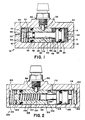
- a first embodiment of a pressure differential switch indicated generally at 10 in accordance with the invention comprises a cylinder body 12 having a substantially closed cylindrical bore 14 therein.
- the opposite ends 16, 18 of the bore 14 are provided with first and second fluid ports 20, 22, respectively, to enable connection to first and second sources of pressurized fluid (not shown).
- port 20 will be connected to the output of the hydraulic booster of an anti-lock braking system and port 22 will be connected to one of the master cylinder outlet ports of the braking system.
- the first and second sources of pressurized fluid may, of course, be any two sources of pressurized fluid the differential pressure of which is desired to be measured or sensed.
- a differential pressure piston assembly 24 is slideably received in the bore 14.
- Assembly 24 includes first and second piston elements 26, 28.
- Element 26 is a generally hollow, cylindrical element having a diameter complementary to the bore 14 and provided with a circumferential recess 30.
- An "O" ring 32 provides a fluid tight seal between piston element 26 and the bore 14.
- Second piston element 28 includes an enlarged cylindrical end portion 34 and a reduced diameter, cylindrical shaft portion 36.
- Enlarged end portion 34 has a diameter complimentary to the bore 14 and is slideably, fluid tightly engaged therewith by means such as an "O" ring 38.
- Shaft portion 36 is slideably received in a complimentary cylindrical bore 40 extending through the piston element 26.
- a fluid tight seal is formed between shaft portion 36 and bore 40 by an "O" ring seal 42.
- Shaft portion 36 is dimensioned such that it extends axially outwardly from the bore 40 and the enlarged head portion 34 is disposed in axially spaced relationship to the adjacent end 46 of piston element 26.
- a spring 48 is compressed between the end 46 and head portion 34.
- the opposite end 50 of shaft portion 36 is fitted with a lock ring 52 which prevents separation of the piston elements 26 and 28. The end 50 extends axially outwardly from the end 54 of shaft portion 36.
- Recess 30 is tapered at its opposite ends and the actuator pin 56 of a switch 58 extends downwardly (as viewed in the drawings) into the recess 30.
- a pair of compression springs 60, 62 received in the chambers 16, 18 yieldably maintain the piston assembly in a center or neutral position as shown in the drawings.
- the piston assembly 24 In operation, in response to normal pressures in the chambers 16, 18, the piston assembly 24 remains in a substantially centered position as is shown in the drawings. In the event of a pressure failure in either chamber 16 or 18, the entire piston assembly 24 will slide as a unit in the direction of the chamber having the low pressure. This movement will cause the recess 30 to move to the right or left to actuate the switch pin 56 and switch 58.
- the spring 48 is relatively stiff and is compressed or preloaded to a predetermined pressure, typically 68,9 bar (1000 psi) in a working embodiment of the invention. Accordingly if the pressure in chamber 16 and chamber 18 is at 68,9 bar (1000 psi) or greater, pressure on the piston elements 26 and 36 will cause compression of the spring 48. This compression of the piston elements does not cause movement of the recess 30 and accordingly does not produce actuation of the switch 58. Simultaneously, the end 50 of shaft portion 36 will come into abutting engagement with end wall 66 of the chamber 16. This prevents further leftward (as viewed in the drawings) movement of the piston element 36.
- a predetermined pressure typically 68,9 bar (1000 psi) in a working embodiment of the invention. Accordingly if the pressure in chamber 16 and chamber 18 is at 68,9 bar (1000 psi) or greater, pressure on the piston elements 26 and 36 will cause compression of the spring 48. This compression of the piston elements does not cause movement of
- Movement of the piston element 26 will not occur so long as the pressure in chamber 16 remains at 68,9 bar (1000 psi) or greater. Accordingly, under these conditions, that is, a pressure of 68,9 bar (1000 psi) or greater in chamber 16, the switch will not respond to differential pressure between the chambers 16 and 18. Accordingly, if the chamber 18 is connected to a master cylinder output and chamber 16 to a hydraulic booster output, it will be seen that the switch will not respond to a differential pressure between the master cylinder and boost pressures so long as the boost pressure remains at a predetermined minimum pressure. The switch will, however, respond to a differential pressure between the two chambers that results from either a failure of the master cylinder pressure or a failure of the boost pressure below its predetermined minimum value.
- the device 100 again includes a cylinder body 112 having a bore 114.
- a piston assembly 126 divides the bore 114 into two pressure chambers 116, 118.
- the chambers 116, 118 are provided with fluid ports 120, 122 which communicate with first and second sources of pressurized fluid (not shown).
- the piston assembly 126 is biased to a neutral or center position as shown in the drawings by means of springs 160, 162 and includes a pair of telescopically engaged piston elements 126 and 128.
- a recess 130 is formed in the piston element 126, recess 130 operatively engaging the pin 156 of a switch 158.
- the neck or shaft portion 136 of piston element 128 is telescopically received in a closed bore 140 formed in the piston element 126.
- the piston elements 126 and 136 are maintained in axially spaced relation by a compression spring 148.
- a differential pressure between chambers 116 and 118 will cause movement of the piston assembly 124 in the direction of the low pressure chamber. This movement produces actuation of switch pin 156 and switch 158 to indicate the differential pressure.
- the piston elements 126 and 136 will collapse one into the other without producing any corresponding actuation of the switch 158.
- This differential pressure switch has particular adaptation in braking systems of the anti-lock type wherein it is desirable to detect differential pressures between the master cylinder output and booster output but wherein it is desired that the switch not respond to short high pressure spikes from the master cylinder which may occur during hard brake applications or during long anti-lock braking operation so long as the pressure in the chamber 116 connected to the boost output remains at or above a predetermined minimum pressure, typically 68,9 bar (1000 psi).
Landscapes
- Engineering & Computer Science (AREA)
- Physics & Mathematics (AREA)
- Fluid Mechanics (AREA)
- Transportation (AREA)
- Mechanical Engineering (AREA)
- Valves And Accessory Devices For Braking Systems (AREA)
- Switches Operated By Changes In Physical Conditions (AREA)
- Transmission Of Braking Force In Braking Systems (AREA)
- Braking Systems And Boosters (AREA)
Abstract
Claims (10)
- Commutateur à pression différentielle comprenant un corps de cylindre (12,112), un alésage allongé (14,114) percé dans le corps de cylindre (12,112) pourvu d'un Premier (20,120) et d'un second orifices (22,122) communiquant avec les extrémités opposées de celul-ci pour relier les dites extrémités aux première et seconde sources de fluide sous pression, un ensemble piston (24,124) logé dans l'alésage (14,114) pour coulisser entre les dites extrémités et y définissant une première (16,116) et une seconde chambres (18,118) de pression, l'ensemble piston (24,124) comprenant un premier (26,126) et un second (28,128) éléments de piston reliés l'un à l'autre pour assurer le mouvement entre une première et une seconde positions relatives ,cet ensemble piston (24,124) pouvant se déplacer d'une position centrée à l'une ou l'autre de deux positions de translation en réponse à une pression différentielle entre les dites première (16,116) et seconde chambres de pression (18,118), un commutateur (58,158) en prise avec un (26,126) des éléments de piston et fonctionnant en réponse au mouvement de l'ensemble piston (24,124) vers l'une ou l'autre des positions de translation , et un premier moyen de déviation (60,62), (160,162) pressant élastiquement l'ensemble piston (24,124) vers une position centrée dans l'alésage (14,114) ,caractérisé en ce que l'ensemble piston (24,124) comprend un second moyen de déviation (48, 148) maintenant élastiquement les premier (26,126) et second 28,128) éléments de piston dans une première position relative l'un par rapport à l'autre,les éléments (26,126;28,128) pouvant se déplacer de la dite première a une seconde position relative en réponse à une pression prédéterminée égale ou supérieure à une valeur minimum dans chacune des chambres de pression (16,116; 18,118), une butée (66,170) en contact avec au moins un (28,128) des éléments (26,126,28,128) pour interdire le déplacement de l'ensemble piston (24,124) vers une des chambres de pression (16,116, 18,118) suffisamment pour interdire le fonctionnement du commutateur (58,158) sans tenir compte de la pression différentielle entre les chambres (16,116, 18,118) lorsque les dits éléments de piston (26,126,28,128) sont dans la seconde position relative, la dite butée (66,170) autorisant le mouvement de l'ensemble piston (24,124) vers les dites positions de translation seulement lorsque les éléments de piston (26,126,28,128) sont dans la première position relative,dans laquelle l'ensemble piston (24,124) peut se déplacer dans l'alésage (14,114) en réponse à une différence de pression dans les première et seconde chambres (16,116, 18,118) et le commutateur (58,158) ne peut fonctionner que lorsque la pression dans les chambres (16,116,18,118) est inférieure à la dite pression prédéterminée.
- Commutateur à pression différentielle selon la revendication 1, caractérisé en ce que les premier (26,126) et second (28,128) éléments de piston sont engagés télescopiquement l'un à l'autre pour effectuer un mouvement relatif axial dans l'alésage (14,114).
- Commutateur à pression différentielle selon la revendication 2, caractérisé en ce que les premier (26,126) et second (28,128) éléments de piston comprennent des surfaces en vis à vis déplacées axialement,le second moyen de déviation(48, 148) incluant un ressort (48,148) comprimé entre les dites surfaces pour y exercer une pression prédéterminée.
- Commutateur à pression différentielle selon la revendication 3, caractérisé en ce que les premier moyens de déviation incluent une paire de ressorts (60,62;160,162) comprimés entre les extrémités opposées de l'ensemble piston (24, 124) et les extrémités opposés respectives de l'alésage (14, 114).
- Commutateur à pression différentielle selon la revendication 4, caractérisé en ce que le premier élément de piston (26) comprend un alésage axial intérieur (40) et que le second élément de piston (28) comprend une partie de tige (36) reçue coulissante à l'intérieur et traversant l'alésage axial (40) à l'extérieur ,la dite tige (36) butant contre une extrémite 66 de l'alésage allongé (14) lorsque les surfaces en vis à vis sont proches l'une de l'autre en réponse à la compression du second moyen de déviation (48) et au mouvement de l'ensemble piston (24,124) à l'une des positions de translation.
- Commutateur à pression différentielle selon la revendication 4, caractérisé en ce que la butée (170) est constituée par un élément s'étendant radialement dans l'alésage (114) entre les surfaces en vis à vis (172,174), l'une de celles-ci (174) au contact de l'élément (170) lorsque les premier (126) et second (128) éléments de piston occupent la seconde position.
- Commutateur à pression différentielle selon la revendication 4, caractérisé en ce qu'il comprend en outre un moyen (52,152) pour limiter axialement le mouvement entre les surfaces en vis à vis.
- Commutateur à pression différentielle selon la revendication 7,caractérisé en ce que le moyen (52,152) pour limiter le mouvement entre les surfaces en vis à vis comprend un élément de blocage (52,152) fixé à un (26,126) des éléments de piston (26,126; 28,128) et engageant axialement en butée une surface de l'autre élément de piston (28,128), lorsque le dit premier élément (26,126) et le dit second élément de piston (28,128)occupent leur première position relative.
- Commutateur à pression différentielle selon la revendication 4, caractérisé en ce qu'il inclut en outre un moyen (32,38; 132,138) assurant l'étancheité au fluide entre les dits premier (26,126) et les dits second éléments (28,128) de piston et l'alésage 14, les dits moyens d'étancheité isolant les première et seconde chambres de pression (18,118).
- Commutateur à pression différentielle selon la revendication 9, caractérisé en ce que la première source de pression est le servo d'un système de freinage hydraulique et l'autre source de pression est la sortie du maître cylindre du système.
Applications Claiming Priority (2)
| Application Number | Priority Date | Filing Date | Title |
|---|---|---|---|
| US06/926,150 US4736990A (en) | 1986-11-03 | 1986-11-03 | Pressure limited differential pressure switch |
| US926150 | 1997-09-09 |
Publications (2)
| Publication Number | Publication Date |
|---|---|
| EP0329688A1 EP0329688A1 (fr) | 1989-08-30 |
| EP0329688B1 true EP0329688B1 (fr) | 1993-02-03 |
Family
ID=25452820
Family Applications (1)
| Application Number | Title | Priority Date | Filing Date |
|---|---|---|---|
| EP87907269A Expired - Lifetime EP0329688B1 (fr) | 1986-11-03 | 1987-10-14 | Commutateur a pression differentielle a limitation de pression |
Country Status (7)
| Country | Link |
|---|---|
| US (1) | US4736990A (fr) |
| EP (1) | EP0329688B1 (fr) |
| JP (1) | JPH07107821B2 (fr) |
| CA (1) | CA1281755C (fr) |
| DE (1) | DE3784073T2 (fr) |
| ES (1) | ES2005670A6 (fr) |
| WO (1) | WO1988003701A1 (fr) |
Families Citing this family (6)
| Publication number | Priority date | Publication date | Assignee | Title |
|---|---|---|---|---|
| DE3819459A1 (de) * | 1988-06-08 | 1989-12-14 | Festo Kg | Druckgesteuerte elektrische schalteinheit |
| US5046313A (en) * | 1989-07-27 | 1991-09-10 | Allied-Signal Inc. | Master cylinder with fluid level and pressure failure detection |
| US4936334A (en) * | 1989-09-29 | 1990-06-26 | Allied-Signal Inc. | Differential pressure shuttle valve |
| US5169212A (en) * | 1990-12-21 | 1992-12-08 | Ford Motor Company | Reversible proportioning valve |
| US5251967A (en) * | 1992-03-25 | 1993-10-12 | Allied-Signal Inc. | Fluid pressure braking system with low pressure warning mechanism |
| US7786392B2 (en) * | 2008-03-17 | 2010-08-31 | Honeywell International Inc. | Self-cleaning pressure switch with a self-sealing diaphragm |
Family Cites Families (8)
| Publication number | Priority date | Publication date | Assignee | Title |
|---|---|---|---|---|
| US3416315A (en) * | 1967-04-10 | 1968-12-17 | Bendix Corp | Brake system failure warning device |
| US3492051A (en) * | 1968-04-25 | 1970-01-27 | Wagner Electric Corp | Control valve |
| US3700286A (en) * | 1970-03-26 | 1972-10-24 | Wagner Electric Corp | Control valve |
| FR2186375B1 (fr) * | 1971-01-15 | 1976-06-18 | Dba | |
| FR2261913B1 (fr) * | 1974-02-25 | 1977-09-16 | Peugeot & Renault | |
| DE2915865A1 (de) * | 1979-04-19 | 1980-11-13 | Teves Gmbh Alfred | Zweikreisdruckregler |
| US4281880A (en) * | 1979-10-01 | 1981-08-04 | The Bendix Corporation | Back-to-back proportioning valve |
| US4604866A (en) * | 1984-09-06 | 1986-08-12 | Allied Corporation | Master cylinder |
-
1986
- 1986-11-03 US US06/926,150 patent/US4736990A/en not_active Expired - Fee Related
-
1987
- 1987-10-14 EP EP87907269A patent/EP0329688B1/fr not_active Expired - Lifetime
- 1987-10-14 WO PCT/US1987/002639 patent/WO1988003701A1/fr not_active Ceased
- 1987-10-14 DE DE8787907269T patent/DE3784073T2/de not_active Expired - Fee Related
- 1987-10-14 JP JP62506882A patent/JPH07107821B2/ja not_active Expired - Lifetime
- 1987-10-28 CA CA000550483A patent/CA1281755C/fr not_active Expired - Lifetime
- 1987-11-03 ES ES8703147A patent/ES2005670A6/es not_active Expired
Also Published As
| Publication number | Publication date |
|---|---|
| DE3784073T2 (de) | 1993-08-19 |
| EP0329688A1 (fr) | 1989-08-30 |
| US4736990A (en) | 1988-04-12 |
| DE3784073D1 (de) | 1993-03-18 |
| JPH07107821B2 (ja) | 1995-11-15 |
| ES2005670A6 (es) | 1989-03-16 |
| CA1281755C (fr) | 1991-03-19 |
| WO1988003701A1 (fr) | 1988-05-19 |
| JPH02501339A (ja) | 1990-05-10 |
Similar Documents
| Publication | Publication Date | Title |
|---|---|---|
| US3975060A (en) | Fluid pressure control device with a failure alarm for a vehicle brake system | |
| US4004839A (en) | Dual circuit brake force regulating device | |
| US3403602A (en) | Dual wheel cylinder | |
| GB2141196A (en) | Vehicle dual circuit hydraulic brake pressure control unit | |
| US4736990A (en) | Pressure limited differential pressure switch | |
| US4477122A (en) | Hydraulic pressure control valve for automobile braking system | |
| US3736031A (en) | Hydraulic brake fluid pressure proportioning valve | |
| US3964795A (en) | Modular proportioner | |
| US3637963A (en) | Brake warning switch with bypass | |
| EP4519131B1 (fr) | Dispositif de régulation de pression, système de freinage, procédé de commande | |
| US5850844A (en) | Pressure reduction valve | |
| EP0402355B1 (fr) | Soupape primaire de dosage a pression equilibree | |
| US5462341A (en) | Proportioning valve | |
| US4337686A (en) | Hydraulic force multiplying device | |
| US4717208A (en) | Brake pressure control valve of a double piping hydraulic braking system | |
| US4070644A (en) | Failure warning switch actuator with automatic reset and proportioner override | |
| GB2056003A (en) | Dual circuit hydraulic control devices | |
| EP0441845B1 (fr) | Soupape de dosage avec equilibrage entre la pression principale et la pression secondaire | |
| US4929033A (en) | Primary and secondary pressure-balanced proportioning valve | |
| EP0020206B1 (fr) | Maître-cylindre à remplissage rapide | |
| CA1120976A (fr) | Regulateur de pression au freinage, avec mecanisme avertisseur de defaillance | |
| US4041449A (en) | Failure warning switch actuator with automatic reset | |
| EP0047202B1 (fr) | Mécanisme d'actionnement d'alarme à remise en équilibre automatique pour un système de freinage à double circuit | |
| US5878574A (en) | Master cylinder having nested concentric pistons | |
| US4995676A (en) | Positioning ring for a hydraulically operated warning device |
Legal Events
| Date | Code | Title | Description |
|---|---|---|---|
| PUAI | Public reference made under article 153(3) epc to a published international application that has entered the european phase |
Free format text: ORIGINAL CODE: 0009012 |
|
| 17P | Request for examination filed |
Effective date: 19890426 |
|
| AK | Designated contracting states |
Kind code of ref document: A1 Designated state(s): DE FR GB IT SE |
|
| RAP1 | Party data changed (applicant data changed or rights of an application transferred) |
Owner name: ALLIED-SIGNAL INC. (A DELAWARE CORPORATION) |
|
| 17Q | First examination report despatched |
Effective date: 19901220 |
|
| GRAA | (expected) grant |
Free format text: ORIGINAL CODE: 0009210 |
|
| AK | Designated contracting states |
Kind code of ref document: B1 Designated state(s): DE FR GB IT SE |
|
| ITF | It: translation for a ep patent filed | ||
| REF | Corresponds to: |
Ref document number: 3784073 Country of ref document: DE Date of ref document: 19930318 |
|
| ET | Fr: translation filed | ||
| PGFP | Annual fee paid to national office [announced via postgrant information from national office to epo] |
Ref country code: GB Payment date: 19931005 Year of fee payment: 7 |
|
| PGFP | Annual fee paid to national office [announced via postgrant information from national office to epo] |
Ref country code: FR Payment date: 19931011 Year of fee payment: 7 Ref country code: DE Payment date: 19931011 Year of fee payment: 7 |
|
| PGFP | Annual fee paid to national office [announced via postgrant information from national office to epo] |
Ref country code: SE Payment date: 19931015 Year of fee payment: 7 |
|
| PLBE | No opposition filed within time limit |
Free format text: ORIGINAL CODE: 0009261 |
|
| STAA | Information on the status of an ep patent application or granted ep patent |
Free format text: STATUS: NO OPPOSITION FILED WITHIN TIME LIMIT |
|
| 26N | No opposition filed | ||
| PG25 | Lapsed in a contracting state [announced via postgrant information from national office to epo] |
Ref country code: GB Effective date: 19941014 |
|
| PG25 | Lapsed in a contracting state [announced via postgrant information from national office to epo] |
Ref country code: SE Effective date: 19941015 |
|
| EAL | Se: european patent in force in sweden |
Ref document number: 87907269.2 |
|
| GBPC | Gb: european patent ceased through non-payment of renewal fee |
Effective date: 19941014 |
|
| PG25 | Lapsed in a contracting state [announced via postgrant information from national office to epo] |
Ref country code: FR Effective date: 19950630 |
|
| PG25 | Lapsed in a contracting state [announced via postgrant information from national office to epo] |
Ref country code: DE Effective date: 19950701 |
|
| EUG | Se: european patent has lapsed |
Ref document number: 87907269.2 |
|
| REG | Reference to a national code |
Ref country code: FR Ref legal event code: ST |
|
| PG25 | Lapsed in a contracting state [announced via postgrant information from national office to epo] |
Ref country code: IT Free format text: LAPSE BECAUSE OF NON-PAYMENT OF DUE FEES;WARNING: LAPSES OF ITALIAN PATENTS WITH EFFECTIVE DATE BEFORE 2007 MAY HAVE OCCURRED AT ANY TIME BEFORE 2007. THE CORRECT EFFECTIVE DATE MAY BE DIFFERENT FROM THE ONE RECORDED. Effective date: 20051014 |