EP0330096A2 - Dispositif de purification de gaz - Google Patents
Dispositif de purification de gaz Download PDFInfo
- Publication number
- EP0330096A2 EP0330096A2 EP89102817A EP89102817A EP0330096A2 EP 0330096 A2 EP0330096 A2 EP 0330096A2 EP 89102817 A EP89102817 A EP 89102817A EP 89102817 A EP89102817 A EP 89102817A EP 0330096 A2 EP0330096 A2 EP 0330096A2
- Authority
- EP
- European Patent Office
- Prior art keywords
- liquid
- chamber
- gas
- wall
- conveying
- Prior art date
- Legal status (The legal status is an assumption and is not a legal conclusion. Google has not performed a legal analysis and makes no representation as to the accuracy of the status listed.)
- Granted
Links
Images


Classifications
-
- B—PERFORMING OPERATIONS; TRANSPORTING
- B01—PHYSICAL OR CHEMICAL PROCESSES OR APPARATUS IN GENERAL
- B01D—SEPARATION
- B01D47/00—Separating dispersed particles from gases, air or vapours by liquid as separating agent
- B01D47/06—Spray cleaning
- B01D47/08—Spray cleaning with rotary nozzles
-
- B—PERFORMING OPERATIONS; TRANSPORTING
- B01—PHYSICAL OR CHEMICAL PROCESSES OR APPARATUS IN GENERAL
- B01D—SEPARATION
- B01D50/00—Combinations of methods or devices for separating particles from gases or vapours
- B01D50/40—Combinations of devices covered by groups B01D45/00 and B01D47/00
Definitions
- the invention relates to a device for gas purification using liquid according to the features specified in the preamble of claim 1.
- Such a device is known from DE-A 33 24 124, which dips a tubular conveying body into the liquid in a container.
- the conveyor body has propeller-like conveyor blades at the lower end.
- the spray body located above the conveying body is also tubular and contains a number of openings from which the liquid conveyed upwards emerges without pressure being built up.
- the spray body contains disks arranged radially on the outside, by means of which the liquid emerging from the openings is distributed.
- the liquid is supposed to adhere to the pane arrangement, flow radially outward and tear off there from the pane in order to be sprayed into an annular spray zone.
- the radius of these disks must be comparatively large, which means that on the one hand a large construction volume is required and on the other hand there are not inconsiderable difficulties with regard to the balancing of the disk arrangement in practice. To avoid an impermissible imbalance, the disks have to be manufactured very precisely and mon be, whereby additional measures for balancing are necessary.
- the disk arrangement acting as an axial fan requires a comparatively large overall volume of the previously known spraying device.
- spray devices of the type mentioned are used for the continuous purification of gases in order to reduce the concentration of the pollutants contained in the gases, where applicable the legal regulations applicable for keeping the air clean must be observed.
- the permissible quantities of pollutants per unit of time (e.g. hour) and per volume should be observed, taking into account the applicable regulations.
- the foreign or pollutants contained in the gas are from the liquid, for. As water, bound and thus washed out of the gas with this.
- the devices are therefore also referred to as gas scrubbers, with alkaline liquids also being used depending on the composition
- the invention is based on the object of designing a device of the type mentioned in such a way that effective gas purification takes place with little design effort, complex piping systems for the liquid, pumps and the like being avoided.
- the device should have a small overall volume and can be easily integrated into existing system parts, laboratory facilities and the like, if necessary subsequently.
- the free space above the experimental chambers, fume cupboards or digestories or similar systems available in laboratories or factory halls should be used and the gas or fume tubes should be able to be used essentially unchanged.
- a high degree of separation with a high degree of functional reliability is to be ensured, the draft or pressure losses in the pipe system of the exhaust gases being small and the amount of liquid escaping with the gas being low.
- the proposed device is characterized by a compact and functionally reliable design, with conventional pumps and line systems for the liquid being dispensed with.
- the tubular conveyor body protrudes directly into the cleaning liquid.
- the distributor system is arranged, by means of which the liquid conveyed upwards, due to the effective centrifugal forces, creates a pressure which sprays the liquid into the chamber through which the gas flows.
- the conveying and spraying system is able to deliver large quantities of liquid with a small drive power. Due to the pressure build-up in the channels upstream of the nozzles, relatively low speeds are sufficient.
- the liquid enters the chamber in the form of a spray or in small droplets, the suspended matter contained in the gas, just like gas particles, depending on the composition, reacting chemically and / or being washed out by means of the liquid.
- the liquid can be fed in and discharged continuously or can be cleaned in conventional treatment plants or the like when a predetermined concentration is reached.
- a combined conveyor and spray system with common storage and a direct drive is expediently provided.
- the conveying and spraying body can have its own storage and can be driven indirectly.
- Another essential function of the device is the flame arrester in the event of an unforeseen fire in the digestorium or in comparable systems, since the liquid reliably extinguishes flames, burning or smoldering particles. The spreading of fires via the downstream exhaust pipes is therefore prevented in a reliable manner.
- the length of the channels arranged in the spray body and directed outwards can be specified in accordance with the required pressure build-up.
- the channels are closed radially on the outside by nozzles, through which the liquid is sprayed into the chamber under pressure.
- the radial dimensions Solutions of the spray system are comparatively small.
- the disk arrangement known from DE-A 33 24 124 mentioned requires comparatively large radial dimensions.
- the axial length of the spray system and thus the entire device according to the invention can also be made small. It is also of particular importance that, in an expedient embodiment, the channels can be arranged not only in the exact radial direction, but also in directions inclined to the axis of rotation.
- the liquid is not only distributed in the radial direction, but it can also be sprayed upwards or downwards according to the inclined arrangement of the channels and associated nozzles, as a result of which a particularly intensive use of the available construction volume and very good atomization and spraying the liquid is achieved in the spray chamber.
- the conveying body has a ring at the lower end with a smaller diameter than the inside diameter of the tube. Furthermore, wall ribs are provided on the inner wall of the conveying body, which, in conjunction with the ring, result in a particularly effective conveying of the liquid.
- the conveying system designed in this way results in a high degree of effectiveness with a small construction volume and generates a rotational flow of the liquid conveyed upwards.
- the conveyor system known from DE-A 33 24 124 already mentioned is designed as an axial pump, which in practice only reaches about 10% of the delivery head of the conveyor system proposed herewith. Due to the improved conveying capacity, in particular the construction volume can be kept small and / or the speed of the drive device for the conveying system and the spraying system can be significantly reduced to achieve a long service life and functional reliability be decorated. Because of the pressure build-up achieved with the spray system proposed according to the invention, the amount of liquid conveyed upwards can be effectively sprayed even at comparatively low speeds. In contrast to this, the known device of the mentioned DE-A must be driven at relatively high speeds so that the liquid can be torn off and sprayed in the required manner at the radial ends of the disk arrangement.
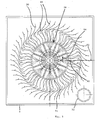
- Fig. 1 shows a housing 2, in the bottom 4 a pipe socket 6 is arranged.
- the bottom 4 is connected to the walls 8 in a liquid-tight manner and the dash-dotted line 10 indicates the surface of a liquid.
- Gases can be water or another cleaning liquid with appropriate chemical properties. If, for example, sulfur oxides or nitrogen oxides are contained in the gas supplied, it is expedient to provide an alkaline cleaning liquid.
- the gas flows into chamber 14, into which the liquid is sprayed by means of the combined delivery and spraying system 16 according to the invention.
- the conveying and spraying system 16 is located behind the drawing plane and is driven from above by an electric motor 18.
- the gas cleaned by means of the liquid arrives at the top via guide elements 20 and from there to the exhaust pipe 22.
- the droplet separator 20 effectively separates the liquid, forming relatively large liquid droplets which drip downwards due to the force of gravity, while the gas flowing upwards and cleaned only has a comparatively low moisture content. Due to the guide elements, the liquid is effectively separated and the liquid loss is kept low.
- the system 16 has a conveyor body 24 at the bottom, which is designed here as a rotating conveyor tube.
- the conveying body 24 protrudes into the liquid and has an opening 26 at the bottom through which the liquid enters and rotates and is thereby conveyed upwards.
- the design of the conveyor body as a conveyor tube with inner wall ribs has proven to be particularly simple and expedient, other systems for generating the rotation can also be provided within the scope of this invention. It is essential in all embodiments that no separate pump circuit with external pipelines and the like is provided.
- the conveying body, however formed, is arranged below the spray system and is driven by it by means of the same motor 18.
- the spray body 34 has a cavity 36 inside, into which the highly pumped liquid passes. Channels 38 lead radially outward from the cavity 36 to spray nozzles 40. When the spray body 34 rotates, the liquid is thrown radially outwards due to the centrifugal forces and is conveyed through the nozzles 40 at high pressure.
- the pressure is predetermined in accordance with the radial length of the channels 38 and the distance of the nozzles 40 from the axis of rotation 42. There is no need to emphasize that the pressure is also largely dependent on the speed.
- the channels 38 shown and the associated nozzles 40 are arranged with their longitudinal axes inclined at an angle of less than 90 ° with respect to the axis of rotation 42.
- the nozzle 41 which can be seen in a frontal view, and its channel, however, lie in a radial plane. It goes without saying that further nozzles and channels, not shown here, are arranged in this radial plane.
- the spray body 34 has a comparatively small axial extent in the direction of the axis of rotation 42 and nevertheless the liquid is sprayed over a large axial height in the chamber 14.
- FIG. 2 shows a further section, the section plane now being behind the drawing plane according to FIG. 1.
- a second pipe socket 7 can now be seen, through which the gas to be cleaned can also flow into the housing 2 from below.
- the baffles with sieve 44 prevent a rotating flow in the area of the outer wall 31 of the conveying body 24 and contamination of the conveying and spraying system.
- the liquid rises in the manner of a parabola on the inner wall 28 of the conveying body 24, indicated by dash-dotted lines.
- At the lower end of the conveyor body 24 there is a ring 30 with the opening 26 the one whose diameter is smaller than the diameter of the inner wall 28.
- the conveying capacity is hereby significantly improved.
- baffles with a sieve 44 are arranged in order to prevent the formation of an annular flow on the outer surface of the conveying body 24. A sinking of the surface of the liquid by rotation near the outer wall of the conveying body 24 and an associated reduction in the conveying capacity are reliably prevented.
- 24 plates can be arranged in the area of the outer wall 31 of the conveying body to prevent an annular flow.
- Such plates are expediently arranged in a star shape relative to the axis of rotation 42. Only plates are arranged in those cases in which it is feared that contamination or substances washed out of the gas or precipitated out by chemical reaction could result in the clogging of a sieve. It has proven expedient to arrange the spray nozzles 40 in different planes and also in different directions with respect to the axis of rotation 42.
- the liquid sprayed in various directions from the spray body 34 is sprayed onto the edges, boundary surfaces or the like present in the interior of the housing 2 with high pressure, and the impact causes the droplets to be further reduced, so that a very fine one is formed in the chamber 14 Spray mist forms, which ensures a very effective cleaning of the gas.
- the liquid in particular water, is supplied through the pipe 46, a nozzle 48 being provided at the upper end of the pipe for the defined specification of the inflow.
- An overflow 50 with a drain pipe can also be seen, the upper edge of which defines the fill level of the liquid or its surface 10.
- the liquid supply is controlled by a sensor that monitors the level.
- the height 52 measured from the lower edge of the base 4 to the upper end of the electric motor 18, is approximately 60 cm in this exemplary embodiment.
- the width of the device which is perpendicular to the plane of the drawing, is approximately 100 cm.
- the device can therefore easily be used for retrofitting digestories, test chambers and the like and can be easily retrofitted on top of such arrangements.
- the device has two pipe sockets, which are expediently arranged and designed in accordance with the usually existing downpipes of such chambers. It can be seen that only such a downpipe has to be removed in order to connect the exhaust pipe 22 to an existing exhaust duct 54 in a simple manner.
- the device is a complete functional unit and the installation of external line systems, pumps and the like is not required.
- a glass pane 55 similar to a porthole, through which the function or the liquid level can be checked by the staff without further ado.
- the device Since the device is arranged directly above the test chamber or the digestorium, it serves in a particularly expedient manner at the same time as a flame arrester. If a fire forms in the test chamber due to any faults, no flames can penetrate into the exhaust duct 54. The liquid sprayed into the chamber 14 brings about a reliable extinguishing, so that, according to the invention, the occurrence of a fire in the discharge duct is prevented with a high degree of certainty.
- FIG. 3 shows an embodiment which results in good integration into a test chamber, the ceiling 56 of which can be seen here in part.
- the here again tubular conveyor body 24 projects through a ceiling opening 58 into a container 60 which is arranged on the underside of the ceiling 56 and the liquid the surface 10 picks up.
- Two plates 32 arranged in a star shape relative to the axis of rotation 42 near the outer wall 31 of the conveying body 24 can be clearly seen here.
- the conveying pipe or the conveying body 24 has webs 62 or wall ribs on the inner wall which are formed corresponding to the ring 30, as a result of which an improved conveying capacity is achieved.
- the embodiments explained at the outset also have such wall ribs or webs for the purpose of increasing the delivery rate.
- the spray body 34 rotates in a spiral channel 64, which is arranged above the ceiling 56.
- the gas to be cleaned flows according to the arrows 12 into the spiral channel 64, which opens into the exhaust pipe 22.
- the liquid is sprayed into the spiral channel 64 by means of the spray nozzles 40 and guided into a drop separator, not shown, from which the deposited drops flow back into the container 60.
- the spiral channel 64 enables a good outflow of the gas with low pressure losses.
- This embodiment is also characterized by a compact design and low weight.
- the conveying body 24 and the spray body 34 are integrated into a structural unit which has a coupling 68 for the shaft of the drive motor 18 at the top.
- the spray body 34 also has the effect of a radial fan wheel. Because of this design, which is essential to the invention, as a fan wheel, the gas to be cleaned is intensively distributed and swirled with the cleaning liquid, thereby ensuring particularly intensive cleaning.
- the escape of gas and liquid in the coupling area is reliably prevented by means of a shaft seal 70.
- the drive motor 18 is supported with its flange in a simple manner on support elements 72, it being possible for simple assembly or, if appropriate, disassembly for maintenance or repair purposes.
- the spiral chamber 64 is sealed in the area of the coupling part 68 in a functionally reliable manner by means of the shaft seal 70.
- the coupling part 68 is also an integral part of the entire delivery and spray system. The feed wheel and drive do not have to be coupled directly be.
- FIG. 4 shows the spiral channel 64 with the spray system 34 in the sectional plane IV according to FIG. 3.
- the spray nozzles 40 are arranged in the circumferential direction between radially outwardly extending partition walls 74. They can also be curved like the blades of a fan.
- the liquid emerging from the nozzles 40 reaches the gas stream flowing past.
- the sprayed-out liquid also reaches the upper and lower walls of the spray system, with the impact on these walls causing the liquid droplets to be further crushed.
- the lower, wheel disk 76 of the spray system is also held by means of the partition walls 74.
- the gas cleaned in the spiral channel 64 flows out through the exhaust pipe 22.
- FIG. 5 shows a section corresponding to FIG. 4, the spray system being designed in accordance with the latter embodiment.
- the spray system 34 is surrounded by guide elements 20.
- These guide elements 20 are fastened in the interior of the housing 2 in a manner not shown here and radially surround the spray system 34. At the same time, they form a droplet separator.
- the housing 2 is arranged according to the spiral channel of the embodiment explained with reference to FIG. 3 on the ceiling of a test chamber, below which the container with the liquid, in which the conveying body engages from above, is arranged in a corresponding manner.
- the exhaust pipe 22 indicated here by dash-dotted lines is located in the ceiling of the housing, that is to say in front of the drawing plane.
- the guide elements 20 have radially inner end edges 78 which extend in the vertical direction or parallel to the axis of rotation of the spray system.
- the inflow area 80 of the fins or guide elements 20 is arranged inclined at an angle 84 to the respective radial plane 82. This angle 84 is specified in such a way that an optimal entry angle in With regard to the lowest possible shock losses.
- the guide plates 20 are curved in a wave-like manner and contain parts 86 projecting into the flow channel. They act in a known manner as droplet separators.
- the radial distance between the rotating spray wheel 34 and the guide elements 20 can be made substantially larger than shown in FIG. 5.
- the droplet separator promotes the formation of large liquid droplets that flow downwards. The moisture content in the gas flowing out through the exhaust pipe 22 is thereby kept low.
Landscapes
- Chemical & Material Sciences (AREA)
- Chemical Kinetics & Catalysis (AREA)
- Gas Separation By Absorption (AREA)
- Treating Waste Gases (AREA)
- Separation Of Particles Using Liquids (AREA)
- Electrical Discharge Machining, Electrochemical Machining, And Combined Machining (AREA)
Applications Claiming Priority (2)
| Application Number | Priority Date | Filing Date | Title |
|---|---|---|---|
| DE3805445A DE3805445A1 (de) | 1988-02-22 | 1988-02-22 | Vorrichtung zur gasreinigung mittels fluessigkeit |
| DE3805445 | 1988-02-22 |
Publications (3)
| Publication Number | Publication Date |
|---|---|
| EP0330096A2 true EP0330096A2 (fr) | 1989-08-30 |
| EP0330096A3 EP0330096A3 (fr) | 1991-07-03 |
| EP0330096B1 EP0330096B1 (fr) | 1994-06-29 |
Family
ID=6347880
Family Applications (1)
| Application Number | Title | Priority Date | Filing Date |
|---|---|---|---|
| EP89102817A Expired - Lifetime EP0330096B1 (fr) | 1988-02-22 | 1989-02-18 | Dispositif de purification de gaz |
Country Status (4)
| Country | Link |
|---|---|
| EP (1) | EP0330096B1 (fr) |
| AT (1) | ATE107872T1 (fr) |
| DE (2) | DE3805445A1 (fr) |
| ES (1) | ES2056129T3 (fr) |
Cited By (4)
| Publication number | Priority date | Publication date | Assignee | Title |
|---|---|---|---|---|
| DE4106319A1 (de) * | 1991-02-28 | 1992-09-03 | Burgert Burdosa | Verfahren und vorrichtung zum reinigen eines gases mit einer fluessigkeit |
| US5685886A (en) * | 1994-10-29 | 1997-11-11 | Friatec Aktiengesellschaft Keramik- Und Kunstoffwerke | Apparatus for gas washing |
| CN113996169A (zh) * | 2021-11-05 | 2022-02-01 | 周嫚嫚 | 一种喷雾喷淋脱硫反应塔 |
| CN117160169A (zh) * | 2023-10-17 | 2023-12-05 | 合肥合安智为科技有限公司 | 一种矿用本安型双流体干雾雾炮 |
Families Citing this family (2)
| Publication number | Priority date | Publication date | Assignee | Title |
|---|---|---|---|---|
| DE9101439U1 (de) * | 1991-02-08 | 1991-05-08 | KT Kunststofftechnik GmbH, 5210 Troisdorf | Laborgaswäscher |
| DE102006002206B3 (de) * | 2006-01-16 | 2007-08-30 | Otto Barnickel | Einrichtung zur Reinigung von schadstoffhaltigen Luftströmen |
Family Cites Families (5)
| Publication number | Priority date | Publication date | Assignee | Title |
|---|---|---|---|---|
| US1992762A (en) * | 1931-04-02 | 1935-02-26 | Pease Anthony Equipment Co | Method of washing gases |
| DE1205494B (de) * | 1953-11-20 | 1965-11-25 | Aeromix Ets | Vorrichtung zum nassen Abscheiden von festen und fluessigen Teilchen aus Gasen oder Daempfen |
| USRE29083E (en) * | 1965-03-26 | 1976-12-21 | Aktieselskabet Niro Atomizer | Atomizer wheel for the atomization of suspensions of hard-wearing materials |
| US3347535A (en) * | 1966-06-03 | 1967-10-17 | Albert J Schimpke | Gas-liquid contact apparatus |
| DE3324124A1 (de) * | 1983-02-05 | 1984-08-09 | Walter Kroll GmbH, 7141 Kirchberg | Spruehvorrichtung |
-
1988
- 1988-02-22 DE DE3805445A patent/DE3805445A1/de active Granted
-
1989
- 1989-02-18 DE DE58907970T patent/DE58907970D1/de not_active Expired - Lifetime
- 1989-02-18 AT AT89102817T patent/ATE107872T1/de not_active IP Right Cessation
- 1989-02-18 EP EP89102817A patent/EP0330096B1/fr not_active Expired - Lifetime
- 1989-02-18 ES ES89102817T patent/ES2056129T3/es not_active Expired - Lifetime
Cited By (5)
| Publication number | Priority date | Publication date | Assignee | Title |
|---|---|---|---|---|
| DE4106319A1 (de) * | 1991-02-28 | 1992-09-03 | Burgert Burdosa | Verfahren und vorrichtung zum reinigen eines gases mit einer fluessigkeit |
| US5685886A (en) * | 1994-10-29 | 1997-11-11 | Friatec Aktiengesellschaft Keramik- Und Kunstoffwerke | Apparatus for gas washing |
| CN113996169A (zh) * | 2021-11-05 | 2022-02-01 | 周嫚嫚 | 一种喷雾喷淋脱硫反应塔 |
| CN117160169A (zh) * | 2023-10-17 | 2023-12-05 | 合肥合安智为科技有限公司 | 一种矿用本安型双流体干雾雾炮 |
| CN117160169B (zh) * | 2023-10-17 | 2024-04-16 | 合肥合安智为科技有限公司 | 一种矿用本安型双流体干雾雾炮 |
Also Published As
| Publication number | Publication date |
|---|---|
| DE3805445C2 (fr) | 1990-10-11 |
| EP0330096B1 (fr) | 1994-06-29 |
| DE58907970D1 (de) | 1994-08-04 |
| DE3805445A1 (de) | 1989-08-24 |
| ES2056129T3 (es) | 1994-10-01 |
| ATE107872T1 (de) | 1994-07-15 |
| EP0330096A3 (fr) | 1991-07-03 |
Similar Documents
| Publication | Publication Date | Title |
|---|---|---|
| DE112004000637B4 (de) | Vorrichtung zum Reinigen eines Gases | |
| DE69712497T2 (de) | Trennzentrifuge | |
| DE2615520A1 (de) | Wasserabscheider der zyklonbauart fuer ein dampf/wassergemisch | |
| DE2202236C3 (de) | Waschvorrichtung | |
| DE19837569B4 (de) | Verfahren zur Reinigung von Filterkerzen eines Kerzenfilters | |
| DE2249844A1 (de) | Vorrichtung und verfahren zum verspruehen von fluessigkeiten | |
| DE2620881C3 (de) | Zerstäuberdüse | |
| DE2257268A1 (de) | Verfahren zur entfernung von fremdstoffen aus gasen | |
| DE3045699A1 (de) | Vorrichtung zur bekaempfung von staub | |
| EP0330096B1 (fr) | Dispositif de purification de gaz | |
| EP4472776B1 (fr) | Dispositif d'évacuation pour un ensemble récipient de réaction, centrifugeuse et procédé de nettoyage d'un ensemble récipient de réaction | |
| DE1287042B (de) | Gaswaescher | |
| CH131306A (de) | Einrichtung zur Herstellung eines intensiven Gemisches mehrerer Medien mittelst Fliehkraftwirkung. | |
| DE2542236C2 (de) | Dünnschichtapparat | |
| DE3324124A1 (de) | Spruehvorrichtung | |
| DE3001280A1 (de) | Gasreiniger | |
| DE2214435C3 (de) | Naßabscheider für staubhaltige Gase oder Luft | |
| DE2719782C3 (de) | Gasreiniger | |
| EP0385983A1 (fr) | Dispositif de nettoyage par voie humide de gaz de fumee. | |
| EP1032466B1 (fr) | Procede pour nettoyer des logements de filtre | |
| DE3715263C2 (fr) | ||
| DE2517661C2 (de) | Vorrichtung zur Schaumbegrenzung bei in einem Flüssigkeitsbehälter auf einer Flüssigkeit schwimmenden Schaum mit quer zum Flüssigkeitsspiegel über eine Antriebsanordnung drehbar angeordneten Schaummesserflügeln zur mechanischen Zerstörung der Schaumblasen | |
| DE3436833A1 (de) | Entluefter fuer wasserumlaufsysteme | |
| DE3438400A1 (de) | Gaswaescher | |
| DE2952800A1 (en) | Entrainment separator and gas-liquid contactor |
Legal Events
| Date | Code | Title | Description |
|---|---|---|---|
| PUAI | Public reference made under article 153(3) epc to a published international application that has entered the european phase |
Free format text: ORIGINAL CODE: 0009012 |
|
| AK | Designated contracting states |
Kind code of ref document: A2 Designated state(s): AT BE CH DE ES FR GB IT LI NL SE |
|
| PUAL | Search report despatched |
Free format text: ORIGINAL CODE: 0009013 |
|
| AK | Designated contracting states |
Kind code of ref document: A3 Designated state(s): AT BE CH DE ES FR GB IT LI NL SE |
|
| RAP1 | Party data changed (applicant data changed or rights of an application transferred) |
Owner name: FRIEDRICHSFELD AKTIENGESELLSCHAFT KERAMIK- UND KUN |
|
| 17P | Request for examination filed |
Effective date: 19910625 |
|
| 17Q | First examination report despatched |
Effective date: 19920515 |
|
| RAP1 | Party data changed (applicant data changed or rights of an application transferred) |
Owner name: FRIATEC AKTIENGESELLSCHAFT KERAMIK- UND KUNSTSTOFF |
|
| ITF | It: translation for a ep patent filed | ||
| GRAA | (expected) grant |
Free format text: ORIGINAL CODE: 0009210 |
|
| AK | Designated contracting states |
Kind code of ref document: B1 Designated state(s): AT BE CH DE ES FR GB IT LI NL SE |
|
| REF | Corresponds to: |
Ref document number: 107872 Country of ref document: AT Date of ref document: 19940715 Kind code of ref document: T |
|
| ET | Fr: translation filed | ||
| GBT | Gb: translation of ep patent filed (gb section 77(6)(a)/1977) |
Effective date: 19940701 |
|
| REF | Corresponds to: |
Ref document number: 58907970 Country of ref document: DE Date of ref document: 19940804 |
|
| REG | Reference to a national code |
Ref country code: ES Ref legal event code: FG2A Ref document number: 2056129 Country of ref document: ES Kind code of ref document: T3 |
|
| EAL | Se: european patent in force in sweden |
Ref document number: 89102817.7 |
|
| PLBE | No opposition filed within time limit |
Free format text: ORIGINAL CODE: 0009261 |
|
| STAA | Information on the status of an ep patent application or granted ep patent |
Free format text: STATUS: NO OPPOSITION FILED WITHIN TIME LIMIT |
|
| 26N | No opposition filed | ||
| PGFP | Annual fee paid to national office [announced via postgrant information from national office to epo] |
Ref country code: SE Payment date: 19980216 Year of fee payment: 10 |
|
| PGFP | Annual fee paid to national office [announced via postgrant information from national office to epo] |
Ref country code: BE Payment date: 19980304 Year of fee payment: 10 |
|
| PG25 | Lapsed in a contracting state [announced via postgrant information from national office to epo] |
Ref country code: SE Free format text: LAPSE BECAUSE OF NON-PAYMENT OF DUE FEES Effective date: 19990219 |
|
| PG25 | Lapsed in a contracting state [announced via postgrant information from national office to epo] |
Ref country code: BE Free format text: LAPSE BECAUSE OF NON-PAYMENT OF DUE FEES Effective date: 19990228 |
|
| BERE | Be: lapsed |
Owner name: FRIATEC A.G. KERAMIK- UND KUNSTSTOFFWERKE Effective date: 19990228 |
|
| EUG | Se: european patent has lapsed |
Ref document number: 89102817.7 |
|
| PGFP | Annual fee paid to national office [announced via postgrant information from national office to epo] |
Ref country code: GB Payment date: 20000128 Year of fee payment: 12 |
|
| PGFP | Annual fee paid to national office [announced via postgrant information from national office to epo] |
Ref country code: FR Payment date: 20000215 Year of fee payment: 12 |
|
| PGFP | Annual fee paid to national office [announced via postgrant information from national office to epo] |
Ref country code: AT Payment date: 20000218 Year of fee payment: 12 Ref country code: CH Payment date: 20000218 Year of fee payment: 12 |
|
| PG25 | Lapsed in a contracting state [announced via postgrant information from national office to epo] |
Ref country code: GB Free format text: LAPSE BECAUSE OF NON-PAYMENT OF DUE FEES Effective date: 20010218 Ref country code: AT Free format text: LAPSE BECAUSE OF NON-PAYMENT OF DUE FEES Effective date: 20010218 |
|
| PG25 | Lapsed in a contracting state [announced via postgrant information from national office to epo] |
Ref country code: CH Free format text: LAPSE BECAUSE OF NON-PAYMENT OF DUE FEES Effective date: 20010228 Ref country code: LI Free format text: LAPSE BECAUSE OF NON-PAYMENT OF DUE FEES Effective date: 20010228 |
|
| REG | Reference to a national code |
Ref country code: CH Ref legal event code: PL |
|
| GBPC | Gb: european patent ceased through non-payment of renewal fee |
Effective date: 20010218 |
|
| PG25 | Lapsed in a contracting state [announced via postgrant information from national office to epo] |
Ref country code: FR Free format text: LAPSE BECAUSE OF NON-PAYMENT OF DUE FEES Effective date: 20011031 |
|
| REG | Reference to a national code |
Ref country code: FR Ref legal event code: ST |
|
| PGFP | Annual fee paid to national office [announced via postgrant information from national office to epo] |
Ref country code: NL Payment date: 20020214 Year of fee payment: 14 |
|
| PGFP | Annual fee paid to national office [announced via postgrant information from national office to epo] |
Ref country code: ES Payment date: 20020221 Year of fee payment: 14 |
|
| PG25 | Lapsed in a contracting state [announced via postgrant information from national office to epo] |
Ref country code: ES Free format text: LAPSE BECAUSE OF NON-PAYMENT OF DUE FEES Effective date: 20030219 |
|
| PG25 | Lapsed in a contracting state [announced via postgrant information from national office to epo] |
Ref country code: NL Free format text: LAPSE BECAUSE OF NON-PAYMENT OF DUE FEES Effective date: 20030901 |
|
| NLV4 | Nl: lapsed or anulled due to non-payment of the annual fee |
Effective date: 20030901 |
|
| REG | Reference to a national code |
Ref country code: ES Ref legal event code: FD2A Effective date: 20030219 |
|
| PG25 | Lapsed in a contracting state [announced via postgrant information from national office to epo] |
Ref country code: IT Free format text: LAPSE BECAUSE OF NON-PAYMENT OF DUE FEES;WARNING: LAPSES OF ITALIAN PATENTS WITH EFFECTIVE DATE BEFORE 2007 MAY HAVE OCCURRED AT ANY TIME BEFORE 2007. THE CORRECT EFFECTIVE DATE MAY BE DIFFERENT FROM THE ONE RECORDED. Effective date: 20050218 |
|
| PGFP | Annual fee paid to national office [announced via postgrant information from national office to epo] |
Ref country code: DE Payment date: 20080229 Year of fee payment: 20 |