EP0330101A2 - Dispositif pour l'analyse d'articulation entre la mâchoire supérieure et la mâchoire inférieure - Google Patents
Dispositif pour l'analyse d'articulation entre la mâchoire supérieure et la mâchoire inférieure Download PDFInfo
- Publication number
- EP0330101A2 EP0330101A2 EP89102843A EP89102843A EP0330101A2 EP 0330101 A2 EP0330101 A2 EP 0330101A2 EP 89102843 A EP89102843 A EP 89102843A EP 89102843 A EP89102843 A EP 89102843A EP 0330101 A2 EP0330101 A2 EP 0330101A2
- Authority
- EP
- European Patent Office
- Prior art keywords
- lower jaw
- plate
- jaw
- upper jaw
- movement
- Prior art date
- Legal status (The legal status is an assumption and is not a legal conclusion. Google has not performed a legal analysis and makes no representation as to the accuracy of the status listed.)
- Granted
Links
- 230000005855 radiation Effects 0.000 claims abstract description 18
- 238000001514 detection method Methods 0.000 claims abstract description 12
- 238000004519 manufacturing process Methods 0.000 description 3
- 230000001055 chewing effect Effects 0.000 description 2
- 238000000034 method Methods 0.000 description 2
- 239000004020 conductor Substances 0.000 description 1
- 210000004513 dentition Anatomy 0.000 description 1
- 238000006073 displacement reaction Methods 0.000 description 1
- 238000011156 evaluation Methods 0.000 description 1
- 239000000463 material Substances 0.000 description 1
- 238000005259 measurement Methods 0.000 description 1
- 230000001502 supplementing effect Effects 0.000 description 1
- 210000001738 temporomandibular joint Anatomy 0.000 description 1
- 230000036346 tooth eruption Effects 0.000 description 1
Images
Classifications
-
- A—HUMAN NECESSITIES
- A61—MEDICAL OR VETERINARY SCIENCE; HYGIENE
- A61C—DENTISTRY; APPARATUS OR METHODS FOR ORAL OR DENTAL HYGIENE
- A61C19/00—Dental auxiliary appliances
- A61C19/04—Measuring instruments specially adapted for dentistry
- A61C19/045—Measuring instruments specially adapted for dentistry for recording mandibular movement, e.g. face bows
Definitions
- the invention relates to a device for analyzing the articulation movement between the upper jaw and lower jaw, in particular with contact of the teeth of the upper jaw and lower jaw.
- a measuring device is used to register the articulation movement, which is attached to the lower jaw and has a bracket projecting towards the lower jaw joints (condyles).
- the so-called condylar pole is scanned and a writing tip of the facebow is aligned with this point.
- a registration sheet is placed under the tip of the pen, on which the movement of the condyles is recorded while the patient is chewing.
- the consistent measuring principle consists in determining the movement of the lower jaw in order to simulate the individual movement of the lower jaw to the upper jaw as precisely as possible in the manufacture of the dental prosthesis in the dental laboratory.
- Further devices have become known for this purpose, e.g. B. the Stereo-Gnathograph-V from Dental-Elektronik KG in 8480 Weiden.
- the mechanical recording system has been replaced by a non-contact motion detection system that has three infrared transmitters and three infrared receivers in the ear area, between which a suitably designed plate can be moved, which is connected to the facebow.
- the movement at the condylar end of the facebow is detected by the non-contact movement detection system and can be recorded electronically.
- nothing has changed in the actual measuring principle.
- the invention has for its object to provide a device of the type mentioned in such a way that an accurate and reliable determination of the movement of the lower jaw relative to the upper jaw is possible in that the articulation movement is not disturbed by parts of the device attached to the lower jaw outside the mouth area.
- This object is achieved according to the invention in a device of the type mentioned at the outset by two plates inserted into the upper jaw and lower jaw, which have a transmitter arrangement with a plurality of radiation sources and a receiver arrangement for the detection of impingement points of the emitted beams.
- a sideways movement of the lower jaw parallel to the upper jaw creates a scratch mark in the form of an arrow on the lower jaw plate, which, particularly at its outer ends, provides information about the function of the temporomandibular joint in the lateral movement of the lower jaw and the detection of the central relation of the jaws based on the position of the jaw Arrowheads allowed.
- the analysis of a chewing movement in which the teeth come into contact with one another is neither provided nor possible.
- the radiation sources and the receiver arrangement are arranged on the same plate and the second plate only functions as a reflector for the emitted beams.
- the embodiment is preferred in which a plate contains the transmitter arrangement (transmitter plate) and the other plate has the receiver arrangement (receiver plate).
- the transmitter arrangement will generally require slightly more height than the receiver arrangement, so that it is expedient to insert the plate with the transmitter arrangement into the jaw, where there is the most space due to the individual anatomical situation.
- two radiation sources which are parallel to one another and at least one radiation source which is at an angle thereto are advantageously used.
- the distance between the point of incidence of the inclined radiation source and one of the radiation sources arranged in parallel varies with the distance between the plates.
- the impingement points of the two radiation sources which are parallel to one another enable the detection of a plane-parallel displacement of the plates relative to one another and a relative tilting movement which leads to a change in the distance between the impingement points of these two radiation sources.
- the radiation sources which are parallel to one another are preferably oriented such that they are substantially perpendicular to the receiver plate during the contact of the teeth of the upper jaw and lower jaw.
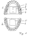
- FIG. 1 shows an upper jaw 1 and a lower jaw 2.
- a first plate 4 carrying radiation sources 3 is inserted, which functions as a transmitter plate, while in the lower jaw 2 a plate 6 carrying a sensor surface 5 is inserted.
- Both plates 4, 6 are fitted with a suitable compensating material 7.
- the first plate 4 (transmitter plate) holds a carrier plate 8 which carries three light sources 3 which act as radiation sources.
- the second plate 6 (receiver plate) inserted in the lower jaw carries a sensor surface 5, which enables the detection of points of incidence of the light beams with the coordinates on the sensor surface 5.
- the sensor surface 5 is scanned in the form of a line, with a defined electrical value being assigned to each point of impact.
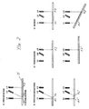
- Figure 2 shows in Figure A a basic arrangement for three radiation sources 3, which are designed here as light sources L1, L2, L3. These three light sources do not have to be independent light generators, but can be, for example, by light be formed conductors to which light signals are supplied by a common light generator. However, normal light bulbs, light-emitting diodes or preferably laser diodes can also be used in a simple manner as light sources L1, L2, L3.
- the three light sources L1, L2, L3 fastened on the transmitter plate 4 are arranged such that two of the light sources, namely L1 and L3, are parallel to one another, while a middle light source L2 arranged on the connecting line of the two light sources L1, L3 emits obliquely to it.
- the three light sources generate points of incidence A1, A2, A3 on the sensor surface 5, the position of which is detected by the sensor surface 5.
- Figure C shows that only one point of impact is required to detect a shift in sensor surface 5.
- the position, for example, of the point of impact A3 on the sensor surface 5 changes when it is shifted parallel to itself, as is illustrated by the point of impact A3 '.
- Figure D shows the detection of an inclination of the two plates 4, 6 to one another.
- the two light sources L1, L3, which are parallel to one another produce impact points A1, A3, their Distance corresponds to the distance between the light sources L1, L3.
- the sensor surface 5 is inclined relative to the transmitter plate 4, impingement points A1 ⁇ , A3 ⁇ arise, the distance from which increases proportionally to the inclination in the direction of the connecting line of the two light sources L1, L3.
- the arrangement shown in FIG. 2 serves to detect the relative movements from lower jaw to upper jaw along a detection line.
- a three-dimensional detection of the movement is easily possible by appropriately supplementing light sources, for example perpendicular to the connecting line of the light sources L1, L2, L3.
- the evaluation of the measured values determined during a movement process is carried out by a computer.
- the determined movement can easily be reproduced in two or three dimensions.
Landscapes
- Health & Medical Sciences (AREA)
- Oral & Maxillofacial Surgery (AREA)
- Life Sciences & Earth Sciences (AREA)
- Engineering & Computer Science (AREA)
- Biomedical Technology (AREA)
- Biophysics (AREA)
- Dentistry (AREA)
- Epidemiology (AREA)
- Animal Behavior & Ethology (AREA)
- General Health & Medical Sciences (AREA)
- Public Health (AREA)
- Veterinary Medicine (AREA)
- Measurement Of The Respiration, Hearing Ability, Form, And Blood Characteristics Of Living Organisms (AREA)
- Dental Tools And Instruments Or Auxiliary Dental Instruments (AREA)
- Investigating Or Analysing Biological Materials (AREA)
- Stacking Of Articles And Auxiliary Devices (AREA)
- Investigating Or Analysing Materials By The Use Of Chemical Reactions (AREA)
- Investigating Or Analyzing Materials By The Use Of Ultrasonic Waves (AREA)
- Apparatus For Radiation Diagnosis (AREA)
Priority Applications (1)
| Application Number | Priority Date | Filing Date | Title |
|---|---|---|---|
| AT89102843T ATE91401T1 (de) | 1988-02-26 | 1989-02-18 | Vorrichtung zur analyse der artikulationsbewegung zwischen oberkiefer und unterkiefer. |
Applications Claiming Priority (2)
| Application Number | Priority Date | Filing Date | Title |
|---|---|---|---|
| DE3806028A DE3806028C1 (fr) | 1988-02-26 | 1988-02-26 | |
| DE3806028 | 1988-02-26 |
Publications (3)
| Publication Number | Publication Date |
|---|---|
| EP0330101A2 true EP0330101A2 (fr) | 1989-08-30 |
| EP0330101A3 EP0330101A3 (en) | 1990-06-27 |
| EP0330101B1 EP0330101B1 (fr) | 1993-07-14 |
Family
ID=6348215
Family Applications (1)
| Application Number | Title | Priority Date | Filing Date |
|---|---|---|---|
| EP89102843A Expired - Lifetime EP0330101B1 (fr) | 1988-02-26 | 1989-02-18 | Dispositif pour l'analyse d'articulation entre la mâchoire supérieure et la mâchoire inférieure |
Country Status (4)
| Country | Link |
|---|---|
| EP (1) | EP0330101B1 (fr) |
| AT (1) | ATE91401T1 (fr) |
| DE (2) | DE3806028C1 (fr) |
| ES (1) | ES2041851T3 (fr) |
Cited By (2)
| Publication number | Priority date | Publication date | Assignee | Title |
|---|---|---|---|---|
| DE10218435B4 (de) * | 2002-04-25 | 2010-03-04 | Zebris Medical Gmbh | Verfahren und Vorrichtung zur 3-dimensionalen Bewegungsanalyse von Zahnoberflächen des Oberkiefers in Relation zum Unterkiefer |
| WO2011147988A2 (fr) | 2010-05-28 | 2011-12-01 | Zebris Medical Gmbh | Instrument dentaire |
Families Citing this family (7)
| Publication number | Priority date | Publication date | Assignee | Title |
|---|---|---|---|---|
| DE3907444C1 (en) * | 1989-03-08 | 1990-08-09 | Dental-Labor Werner Puckert, 4236 Hamminkeln, De | Device for recording the vertical dimension and central occlusion in total or partial occlusion disturbance |
| DD297059A5 (de) * | 1990-08-14 | 1992-01-02 | �������`�����`������������k�� | Vorrichtung zur zweidimensionalen intraoralen registrierung der unterkieferbewegung und der kieferschlusskraft |
| DE19830617C1 (de) * | 1998-07-09 | 1999-09-09 | Ars Dental Gmbh | Vorrichtung und Verfahren zur Artikulationsanaylse |
| DE10004226C1 (de) * | 2000-02-01 | 2001-07-05 | Ars Dental Gmbh | Vorrichtung und Verfahren zur Artikulationsanalyse |
| DE102006011787A1 (de) * | 2006-03-15 | 2007-09-20 | Rahnenführer, Claus | Vorrichtung und Verfahren zur dreidimensionalen Messung der Kieferstellung |
| DE102012001653B4 (de) | 2011-03-25 | 2021-06-24 | Andreas Vogel | Vorrichtung und Verfahren zur Messung kiefergelenkgeführter Unterkieferbewegungen |
| DE102016120583B3 (de) * | 2016-10-27 | 2018-04-12 | Sicat Gmbh & Co. Kg | Verfahren zur Aufnahme von Kieferbewegungen |
Family Cites Families (4)
| Publication number | Priority date | Publication date | Assignee | Title |
|---|---|---|---|---|
| US3390459A (en) * | 1959-09-17 | 1968-07-02 | Seidenberg Murray | Dental apparatus and method |
| US4234306A (en) * | 1979-07-18 | 1980-11-18 | Hbti | Method and apparatus for sensing jaw position and movements and utilizing sensed data |
| DE2936328A1 (de) * | 1979-09-08 | 1981-03-12 | Becker Dental-Labor Gmbh, 5100 Aachen | Verfahren und vorrichtung zum reproduzieren von kieferbewegungen. |
| JPS58175544A (ja) * | 1982-04-07 | 1983-10-14 | 株式会社モリタ製作所 | 下顎運動診断装置 |
-
1988
- 1988-02-26 DE DE3806028A patent/DE3806028C1/de not_active Expired
-
1989
- 1989-02-18 AT AT89102843T patent/ATE91401T1/de not_active IP Right Cessation
- 1989-02-18 EP EP89102843A patent/EP0330101B1/fr not_active Expired - Lifetime
- 1989-02-18 DE DE8989102843T patent/DE58904888D1/de not_active Expired - Fee Related
- 1989-02-18 ES ES198989102843T patent/ES2041851T3/es not_active Expired - Lifetime
Cited By (3)
| Publication number | Priority date | Publication date | Assignee | Title |
|---|---|---|---|---|
| DE10218435B4 (de) * | 2002-04-25 | 2010-03-04 | Zebris Medical Gmbh | Verfahren und Vorrichtung zur 3-dimensionalen Bewegungsanalyse von Zahnoberflächen des Oberkiefers in Relation zum Unterkiefer |
| WO2011147988A2 (fr) | 2010-05-28 | 2011-12-01 | Zebris Medical Gmbh | Instrument dentaire |
| DE102010021934A1 (de) | 2010-05-28 | 2011-12-01 | Zebris Medical Gmbh | Dental-Werkzeug |
Also Published As
| Publication number | Publication date |
|---|---|
| ATE91401T1 (de) | 1993-07-15 |
| EP0330101B1 (fr) | 1993-07-14 |
| DE58904888D1 (de) | 1993-08-19 |
| EP0330101A3 (en) | 1990-06-27 |
| ES2041851T3 (es) | 1993-12-01 |
| DE3806028C1 (fr) | 1989-05-18 |
Similar Documents
| Publication | Publication Date | Title |
|---|---|---|
| EP2099383B1 (fr) | Procédé et dispositif de transfert, par rapport à un axe d'articulation, d'un modèle de mâchoire | |
| DE3500605A1 (de) | Vorrichtung zur messung der positionen und bewegungen des unterkiefers relativ zum oberkiefer | |
| DE2439125A1 (de) | Vorrichtung fuer die zahnmedizin | |
| EP3422996B1 (fr) | Dispositif et procédé pour mesurer un mouvement du maxillaire inférieur | |
| EP0025201A1 (fr) | Articulateur pour reproduire les mouvements de la mâchoire d'un patient | |
| DE3807578C2 (fr) | ||
| DE3725205A1 (de) | Tastkopf fuer koordinatenmessgeraete | |
| EP0330101B1 (fr) | Dispositif pour l'analyse d'articulation entre la mâchoire supérieure et la mâchoire inférieure | |
| WO2018130656A1 (fr) | Système et procédé de mesure d'un mouvement d'une mâchoire inférieure | |
| CH643728A5 (de) | Abtastvorrichtung fuer mandibularbewegungen. | |
| EP0371272B1 (fr) | Dispositif pour la prise d'occlusion de molaires | |
| DE102004002953B4 (de) | Verfahren und Vorrichtung zur Bestimmung aller Bewegungsfreiheitsgrade und Positionen des Unterkiefers bezüglich des Oberkiefers | |
| DD297059A5 (de) | Vorrichtung zur zweidimensionalen intraoralen registrierung der unterkieferbewegung und der kieferschlusskraft | |
| DE2950847C2 (de) | Zahnärztliche Vorrichtung zur Erfassung der räumlichen Lage und Bewegung des menschlichen Unterkiefers in bezug zur Schädelreferenzebene des Patienten | |
| DE2825204A1 (de) | Vorrichtung zur dreidimensionalen erfassung und aufzeichnung der bewegung des unterkiefers, insbesondere der kiefergelenke eines patienten | |
| EP0332892B1 (fr) | Dispositif pour déterminer le mouvement relatif de deux emplacements de mesure | |
| EP1650529A1 (fr) | Dispositif et procédé pour balayer plusieurs objets | |
| DE3123526C2 (de) | Verfahren zum ein- bis dreidimensionalen Vermessen von Kiefer- bzw. Kiefergelenkbewegungen und Anordnung zur Durchführung des Verfahrens | |
| EP0229266A2 (fr) | Méthode de reconstruction des dents de la mâchoire supérieure | |
| DE10004226C1 (de) | Vorrichtung und Verfahren zur Artikulationsanalyse | |
| DE19830617C1 (de) | Vorrichtung und Verfahren zur Artikulationsanaylse | |
| DE10236333A1 (de) | Vorrichtung und Verfahren zur Artikulationsanalyse | |
| DE102009055848B4 (de) | Verfahren zur Bestimmung und automatisierten Korrektur der Gelenkraumsituation im Bereich des Kiefers eines Patienten sowie dazu geeignetes Gelenkraumwerkzeug | |
| DE2832838C2 (de) | Dental-Pantographie-Gerät und dazugehöriger teiljustierbarer Artikulator | |
| DE3907444C1 (en) | Device for recording the vertical dimension and central occlusion in total or partial occlusion disturbance |
Legal Events
| Date | Code | Title | Description |
|---|---|---|---|
| PUAI | Public reference made under article 153(3) epc to a published international application that has entered the european phase |
Free format text: ORIGINAL CODE: 0009012 |
|
| AK | Designated contracting states |
Kind code of ref document: A2 Designated state(s): AT BE CH DE ES FR GB GR IT LI LU NL SE |
|
| PUAL | Search report despatched |
Free format text: ORIGINAL CODE: 0009013 |
|
| RHK1 | Main classification (correction) |
Ipc: A61C 19/04 |
|
| AK | Designated contracting states |
Kind code of ref document: A3 Designated state(s): AT BE CH DE ES FR GB GR IT LI LU NL SE |
|
| 17P | Request for examination filed |
Effective date: 19901210 |
|
| 17Q | First examination report despatched |
Effective date: 19920423 |
|
| GRAA | (expected) grant |
Free format text: ORIGINAL CODE: 0009210 |
|
| AK | Designated contracting states |
Kind code of ref document: B1 Designated state(s): AT BE CH DE ES FR GB GR IT LI LU NL SE |
|
| REF | Corresponds to: |
Ref document number: 91401 Country of ref document: AT Date of ref document: 19930715 Kind code of ref document: T |
|
| GBT | Gb: translation of ep patent filed (gb section 77(6)(a)/1977) |
Effective date: 19930712 |
|
| REF | Corresponds to: |
Ref document number: 58904888 Country of ref document: DE Date of ref document: 19930819 |
|
| ET | Fr: translation filed | ||
| ITF | It: translation for a ep patent filed | ||
| REG | Reference to a national code |
Ref country code: GR Ref legal event code: FG4A Free format text: 3008872 |
|
| REG | Reference to a national code |
Ref country code: ES Ref legal event code: FG2A Ref document number: 2041851 Country of ref document: ES Kind code of ref document: T3 |
|
| EPTA | Lu: last paid annual fee | ||
| PLBE | No opposition filed within time limit |
Free format text: ORIGINAL CODE: 0009261 |
|
| STAA | Information on the status of an ep patent application or granted ep patent |
Free format text: STATUS: NO OPPOSITION FILED WITHIN TIME LIMIT |
|
| 26N | No opposition filed | ||
| EAL | Se: european patent in force in sweden |
Ref document number: 89102843.3 |
|
| PGFP | Annual fee paid to national office [announced via postgrant information from national office to epo] |
Ref country code: LU Payment date: 19950201 Year of fee payment: 7 |
|
| PGFP | Annual fee paid to national office [announced via postgrant information from national office to epo] |
Ref country code: SE Payment date: 19950215 Year of fee payment: 7 |
|
| PGFP | Annual fee paid to national office [announced via postgrant information from national office to epo] |
Ref country code: GR Payment date: 19950216 Year of fee payment: 7 |
|
| PGFP | Annual fee paid to national office [announced via postgrant information from national office to epo] |
Ref country code: NL Payment date: 19950228 Year of fee payment: 7 Ref country code: ES Payment date: 19950228 Year of fee payment: 7 Ref country code: AT Payment date: 19950228 Year of fee payment: 7 |
|
| PGFP | Annual fee paid to national office [announced via postgrant information from national office to epo] |
Ref country code: BE Payment date: 19950301 Year of fee payment: 7 |
|
| PG25 | Lapsed in a contracting state [announced via postgrant information from national office to epo] |
Ref country code: LU Free format text: LAPSE BECAUSE OF NON-PAYMENT OF DUE FEES Effective date: 19960218 Ref country code: AT Effective date: 19960218 |
|
| PG25 | Lapsed in a contracting state [announced via postgrant information from national office to epo] |
Ref country code: SE Effective date: 19960219 Ref country code: ES Free format text: LAPSE BECAUSE OF NON-PAYMENT OF DUE FEES Effective date: 19960219 |
|
| PG25 | Lapsed in a contracting state [announced via postgrant information from national office to epo] |
Ref country code: BE Effective date: 19960228 |
|
| BERE | Be: lapsed |
Owner name: SCHRADER ERHARD Effective date: 19960228 |
|
| PG25 | Lapsed in a contracting state [announced via postgrant information from national office to epo] |
Ref country code: GR Free format text: THE PATENT HAS BEEN ANNULLED BY A DECISION OF A NATIONAL AUTHORITY Effective date: 19960831 |
|
| PG25 | Lapsed in a contracting state [announced via postgrant information from national office to epo] |
Ref country code: NL Effective date: 19960901 |
|
| REG | Reference to a national code |
Ref country code: GR Ref legal event code: MM2A Free format text: 3008872 |
|
| NLV4 | Nl: lapsed or anulled due to non-payment of the annual fee |
Effective date: 19960901 |
|
| PGFP | Annual fee paid to national office [announced via postgrant information from national office to epo] |
Ref country code: CH Payment date: 19980220 Year of fee payment: 10 |
|
| PGFP | Annual fee paid to national office [announced via postgrant information from national office to epo] |
Ref country code: GB Payment date: 19990204 Year of fee payment: 11 |
|
| PGFP | Annual fee paid to national office [announced via postgrant information from national office to epo] |
Ref country code: DE Payment date: 19990205 Year of fee payment: 11 |
|
| PGFP | Annual fee paid to national office [announced via postgrant information from national office to epo] |
Ref country code: FR Payment date: 19990215 Year of fee payment: 11 |
|
| PG25 | Lapsed in a contracting state [announced via postgrant information from national office to epo] |
Ref country code: LI Free format text: LAPSE BECAUSE OF NON-PAYMENT OF DUE FEES Effective date: 19990228 Ref country code: CH Free format text: LAPSE BECAUSE OF NON-PAYMENT OF DUE FEES Effective date: 19990228 |
|
| REG | Reference to a national code |
Ref country code: ES Ref legal event code: FD2A Effective date: 19990301 |
|
| REG | Reference to a national code |
Ref country code: CH Ref legal event code: PL |
|
| PG25 | Lapsed in a contracting state [announced via postgrant information from national office to epo] |
Ref country code: GB Free format text: LAPSE BECAUSE OF NON-PAYMENT OF DUE FEES Effective date: 20000218 |
|
| GBPC | Gb: european patent ceased through non-payment of renewal fee |
Effective date: 20000218 |
|
| PG25 | Lapsed in a contracting state [announced via postgrant information from national office to epo] |
Ref country code: FR Free format text: LAPSE BECAUSE OF NON-PAYMENT OF DUE FEES Effective date: 20001031 |
|
| PG25 | Lapsed in a contracting state [announced via postgrant information from national office to epo] |
Ref country code: DE Free format text: LAPSE BECAUSE OF NON-PAYMENT OF DUE FEES Effective date: 20001201 |
|
| REG | Reference to a national code |
Ref country code: FR Ref legal event code: ST |
|
| PG25 | Lapsed in a contracting state [announced via postgrant information from national office to epo] |
Ref country code: IT Free format text: LAPSE BECAUSE OF NON-PAYMENT OF DUE FEES;WARNING: LAPSES OF ITALIAN PATENTS WITH EFFECTIVE DATE BEFORE 2007 MAY HAVE OCCURRED AT ANY TIME BEFORE 2007. THE CORRECT EFFECTIVE DATE MAY BE DIFFERENT FROM THE ONE RECORDED. Effective date: 20050218 |