EP0330164A2 - Dispositif de mise hors circuit partielle d'un système de signalisation routière - Google Patents
Dispositif de mise hors circuit partielle d'un système de signalisation routière Download PDFInfo
- Publication number
- EP0330164A2 EP0330164A2 EP89103065A EP89103065A EP0330164A2 EP 0330164 A2 EP0330164 A2 EP 0330164A2 EP 89103065 A EP89103065 A EP 89103065A EP 89103065 A EP89103065 A EP 89103065A EP 0330164 A2 EP0330164 A2 EP 0330164A2
- Authority
- EP
- European Patent Office
- Prior art keywords
- signal
- switch
- sts
- protection module
- lamp
- Prior art date
- Legal status (The legal status is an assumption and is not a legal conclusion. Google has not performed a legal analysis and makes no representation as to the accuracy of the status listed.)
- Granted
Links
Images


Classifications
-
- G—PHYSICS
- G08—SIGNALLING
- G08G—TRAFFIC CONTROL SYSTEMS
- G08G1/00—Traffic control systems for road vehicles
- G08G1/097—Supervising of traffic control systems, e.g. by giving an alarm if two crossing streets have green light simultaneously
-
- G—PHYSICS
- G06—COMPUTING OR CALCULATING; COUNTING
- G06V—IMAGE OR VIDEO RECOGNITION OR UNDERSTANDING
- G06V10/00—Arrangements for image or video recognition or understanding
- G06V10/70—Arrangements for image or video recognition or understanding using pattern recognition or machine learning
- G06V10/77—Processing image or video features in feature spaces; using data integration or data reduction, e.g. principal component analysis [PCA] or independent component analysis [ICA] or self-organising maps [SOM]; Blind source separation
- G06V10/771—Feature selection, e.g. selecting representative features from a multi-dimensional feature space
Definitions
- the invention relates to a device for the partial shutdown of a road traffic signal system with a plurality of signal transmitters or signal groups and a node control device, which has a signal control device and an associated, microprocessor-controlled monitoring device for signal backup with at least two microprocessors with associated program and data memories, with a plurality of sensor and groupable groups Lamp switches and with a fail-safe evaluation circuit.
- a microprocessor-controlled monitoring device for road traffic signal systems with several sensor groups and a fail-safe evaluation circuit in which signaling states (e.g. sampled) signaling states (alternating operating voltages and currents) detected by the sensor circuits are to be compared with reference signals. If the road traffic signal system and / or the monitoring device works correctly, each microprocessor emits the same clock pulses in pulse sequences, but with the phase position shifted by 180 ° relative to one another. These are evaluated in the fail-safe evaluation circuit. In the event of a fault or an error, the entire road traffic signal system is switched off.
- signaling states e.g. sampled
- signaling states alternating operating voltages and currents
- the object of the invention is to design a road traffic signal system with such a monitoring device such that individual areas of the road traffic signal system, i.e. partial nodes, can be switched off independently if in a partial area of the road traffic signal system, i.e. for a subnode, a fault occurs.
- a single device control and common signal protection module common to all subnodes and a separate one for each subnode Evaluation module and lamp switch group with a shutdown device for the associated signal transmitter is provided that the individual lamp switches of the lamp switch groups are controlled by the device control and monitored by the signal protection module via an address and sensor bus, and that with the signal protection module the connected evaluation modules independently of one another in the event of a fault in a node to the relevant lamp switch group or switch-off device, give a switch-off signal or switch-over signal to flashing yellow.
- the road traffic signal system has a signal protection common to all subnodes with a common control logic but separate evaluation devices and switch-off paths. This means that the basic part of the signal protection remains the same, only the fail-safe switch-off paths are provided separately for the individual subnodes. This results in the advantage of much simpler equipment with a clear structure and a central error display and reporting option.
- Another advantage is that the node that is switched off is still monitored by the signal protection module via the lamp switches and the evaluation modules. If, for example, a green signal occurs in the switched-off sub-node due to a cable shortage, which leads to a dangerous conflict situation of the entire intersection, the entire system is switched off via an emergency stop signal.
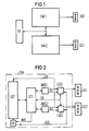
- FIG. 1 shows how a very large traffic node with, for example, two road traffic signal systems SVA1 and SVA2 with the associated signal transmitters SG1 and SG2 has been controlled with the help of a higher-level traffic computer VR.
- the node control device has a device control GST (control part) which, on the one hand, is in data exchange with the signal protection module STS.
- the device control is connected to the respective lamp switch groups LSG1, LSG2 for the subnodes LSG1, LSG2, the control signals LSA being transmitted by the device control GST for the individual lamp switches of the lamp switch groups. All lamp switches are connected to the signal protection module STS with a sensor bus SB and an address bus AB, shown here as a single data bus DB.
- the evaluation module AWS1, AWS2, ... provided for each subnode is in data exchange with the signal protection module and, on the other hand, give the switch-off signal TA1, TA2, ... to the relevant lamp switch group LSG1, LSG2, ... in the event of a fault in a subnode that the associated signal generators SG1, SG2, ... are switched off or switched to flashing yellow.
- Each lamp switch LS1, LS2, ... has switches and sensors for monitoring the currents (three red lamp circuits) and voltages (red, yellow and green) of the signal transmitters.
- the outputs of the voltage and current sensors lead to the common SB sensor bus.
- This is carried by the individual lamp switches LS1, LS2, ... via a dual-port circuit DPIC on the signal protection module STS.
- the dual port circuit DPIC can be a custom IC.
- the sensor signals go to the two microprocessors PROA and PROB on the signal protection module STS via this circuit.
- the microprocessor PROA is mainly intended for processing application-specific data, such as hostility matrix, while the microprocessor PROB processes application-independent data, such as signal detection, system testing.
- application-specific data such as hostility matrix
- microprocessor PROB processes application-independent data, such as signal detection, system testing.
- the use of the DPIC DualPort circuit eliminates the complex wiring of the individual sensor circuits.
- the use of the microprocessors also has the advantage of convenient display of error or fault messages. Overall, the system according to the invention enables the system to be implemented more cost-effectively.
- the reference voltages RES1, ... for the individual signal transmitters are monitored on the respective evaluation module AWS1, AWS2, ... and sent to the signal protection module STS, where they are processed and evaluated with the reference signals by the voltage sensors.
- the safe functioning of the signal protection and thus also of the two microprocessors is monitored by a further data exchange within the signal protection module and with the respective evaluation modules.
- the microprocessor PROB checks the function of processing the hostility matrix and the alarm generation of the processor PROA.
- the microprocessor PROA sends alarm signals ALA1, ALA2, ... and the microprocessor PROB alarm suppression signals ALU1, ALU2, ... to the respective evaluation module AWS1, AWS2, ..., whereby these signals are evaluated in a fail-safe EXOR. If the alarm suppression signal ALU is absent for a certain time, the signal protection device STS responds, i.e. the relevant evaluation module AWS sends a shutdown signal AS to the corresponding shutdown contact, i.e. that, for example, relay K1 drops out for the sub-node concerned.
- FIG. 3 shows schematically the control part of the node control device in the form of the device control GST, the associated lamp switches in the form of a series of respective lamp switch assemblies LSG1 to LSG3 and the signal protection assembly STS.
- the individual lamp switches LS1, LS2, ... are combined here for three subnodes, each with a respective one Signal generators SG1 to SG3 are marked for the partial area of an intersection.
- the switch-off path of a respective partial node is indicated with the contacts K1 to K3.
- the individual lamp switches LS are switched by the device control GST with the help of the lamp switch control LSA.
- the lamp switches are connected on the one hand to an address bus AB and, on the other hand, to the sensor bus SB with the signal protection module STS.
- a separate evaluation module AWS1 to AWS3 is provided for each subnode, which is in the bidirectional data exchange with the signal protection module STS and, on the other hand, can give a switch-off signal AS2, AS3 to the relevant switch-off contact K1 to K3 of the subnode in the event of a fault. If a malfunction occurs within a subnode and this malfunction has no effect on the overall node, which is recognized by the common signal protection STS, the subnode is switched off via the evaluation module AWS. If the signal protection module STS detects a malfunction or a malfunction affecting the overall node, the overall node is switched off via an emergency stop signal NAS and the main switch HS, which is indicated by ASG and K1 to K3.
- the dual-port circuit DTEC can have a comparator VER, which receives data from both microprocessors in order to monitor the correct functioning of the processors and the fuse module.
- the output of the comparator sends a comparator signal VERN to the respective evaluation group AWS to an evaluation circuit arranged there.
- There the signals from the comparator test (VERN) and another signal SPRZ are evaluated.
- the pulse / pause ratio of the respective signals is evaluated. If the pulse-pause ratio is exceeded in an impermissible manner, or if the comparison signal fails to appear, an incorrect behavior of the microprocessor or the comparator is concluded and the overall node is switched off.
Landscapes
- Engineering & Computer Science (AREA)
- Physics & Mathematics (AREA)
- General Physics & Mathematics (AREA)
- Computer Vision & Pattern Recognition (AREA)
- Theoretical Computer Science (AREA)
- Computing Systems (AREA)
- Artificial Intelligence (AREA)
- Databases & Information Systems (AREA)
- Evolutionary Computation (AREA)
- General Health & Medical Sciences (AREA)
- Medical Informatics (AREA)
- Software Systems (AREA)
- Health & Medical Sciences (AREA)
- Multimedia (AREA)
- Traffic Control Systems (AREA)
Priority Applications (1)
| Application Number | Priority Date | Filing Date | Title |
|---|---|---|---|
| AT89103065T ATE93644T1 (de) | 1988-02-25 | 1989-02-22 | Einrichtung zur teilabschaltung einer strassenverkehrssignalanlage. |
Applications Claiming Priority (2)
| Application Number | Priority Date | Filing Date | Title |
|---|---|---|---|
| DE3805949A DE3805949A1 (de) | 1988-02-25 | 1988-02-25 | Einrichtung zur teilabschaltung einer strassenverkehrssignalanlage |
| DE3805949 | 1988-02-25 |
Publications (3)
| Publication Number | Publication Date |
|---|---|
| EP0330164A2 true EP0330164A2 (fr) | 1989-08-30 |
| EP0330164A3 EP0330164A3 (fr) | 1991-09-25 |
| EP0330164B1 EP0330164B1 (fr) | 1993-08-25 |
Family
ID=6348172
Family Applications (1)
| Application Number | Title | Priority Date | Filing Date |
|---|---|---|---|
| EP89103065A Expired - Lifetime EP0330164B1 (fr) | 1988-02-25 | 1989-02-22 | Dispositif de mise hors circuit partielle d'un système de signalisation routière |
Country Status (3)
| Country | Link |
|---|---|
| EP (1) | EP0330164B1 (fr) |
| AT (1) | ATE93644T1 (fr) |
| DE (2) | DE3805949A1 (fr) |
Cited By (9)
| Publication number | Priority date | Publication date | Assignee | Title |
|---|---|---|---|---|
| WO1994002919A1 (fr) * | 1992-07-22 | 1994-02-03 | Remo Pavarotti | Systeme de commande automatique de feux dans une installation d'illumination a circuits en serie, notamment de feux de signalisation d'aeroport |
| AU696654B2 (en) * | 1995-04-13 | 1998-09-17 | Adt Services Ag | Conflict monitor |
| DE19716576C1 (de) * | 1997-04-21 | 1999-01-07 | Stuehrenberg Gmbh Elektrobau S | Verfahren zur Verkehrssignalsteuerung |
| EP0942401A3 (fr) * | 1998-03-13 | 2000-08-30 | Siemens Aktiengesellschaft | Méthode et dispositif pour la fiabilité du signal dans les agencements de feu de signalisation |
| US6132462A (en) * | 1995-12-22 | 2000-10-17 | Santen Pharmaceutical Co., Ltd. | Copolymers formed from three components and intraocular lenses made thereof |
| DE19848405C2 (de) * | 1997-04-21 | 2002-10-10 | Stuehrenberg Gmbh Elektrobau S | Verfahren zur Verkehrssignalsteuerung |
| CN102024340A (zh) * | 2010-12-30 | 2011-04-20 | 广东大榕树信息科技有限公司 | 交通灯监控设备及其监控方法 |
| CN102509472A (zh) * | 2011-11-03 | 2012-06-20 | 安徽科力信息产业有限责任公司 | 一种智能交通信号控制机的独立故障检测与处理电路 |
| CN108417073A (zh) * | 2018-05-18 | 2018-08-17 | 上海会为智能技术有限公司 | 一种信号灯运行状态显示方法、装置、设备和介质 |
Families Citing this family (4)
| Publication number | Priority date | Publication date | Assignee | Title |
|---|---|---|---|---|
| DE3930877C1 (en) * | 1989-09-15 | 1990-10-18 | Stuehrenberg Gmbh, 4930 Detmold, De | Traffic signal system safety circuit - has two processors receiving signal state combinations for checking their reliability |
| DE19940636C2 (de) * | 1999-08-26 | 2003-11-27 | Stuehrenberg Gmbh Elektrobau S | Verkehrsrechner |
| US20050032449A1 (en) | 2003-08-06 | 2005-02-10 | Lovasic Susan L. | Lightweight protective apparel |
| CN107356883B (zh) * | 2017-08-09 | 2023-11-07 | 安徽科力信息产业有限责任公司 | 一种基于电流有效值的信号灯故障检测装置及方法 |
Family Cites Families (6)
| Publication number | Priority date | Publication date | Assignee | Title |
|---|---|---|---|---|
| DE33761C (de) * | 1885-06-16 | 1885-11-23 | G. A. F. MÜLLER in Berlin SW., Gneisenaustr. 109 | Kreiselmusikwerk |
| US4135145A (en) * | 1976-09-07 | 1979-01-16 | Solid State Devices, Inc. | Error detecting circuit for a traffic control system |
| DE2951932C2 (de) * | 1979-12-21 | 1983-08-18 | Siemens AG, 1000 Berlin und 8000 München | Einrichtung zur signaltechnisch sicheren Steuerung und Überwachung |
| DE3337700A1 (de) * | 1983-10-17 | 1985-05-02 | Stührenberg, Rolf, 4930 Detmold | Vorrichtung zur signalsicherung bei lichtzeichenanlagen |
| DE3428444A1 (de) * | 1984-08-01 | 1986-02-06 | Siemens AG, 1000 Berlin und 8000 München | Ueberwachungseinrichtung fuer verkehrssignalanlagen |
| DE3771946D1 (de) * | 1986-06-25 | 1991-09-12 | Siemens Ag | Ueberwachungseinrichtung fuer signallampen einer strassenverkehrssignalanlage. |
-
1988
- 1988-02-25 DE DE3805949A patent/DE3805949A1/de active Granted
-
1989
- 1989-02-22 AT AT89103065T patent/ATE93644T1/de not_active IP Right Cessation
- 1989-02-22 DE DE89103065T patent/DE58905347D1/de not_active Expired - Fee Related
- 1989-02-22 EP EP89103065A patent/EP0330164B1/fr not_active Expired - Lifetime
Cited By (11)
| Publication number | Priority date | Publication date | Assignee | Title |
|---|---|---|---|---|
| WO1994002919A1 (fr) * | 1992-07-22 | 1994-02-03 | Remo Pavarotti | Systeme de commande automatique de feux dans une installation d'illumination a circuits en serie, notamment de feux de signalisation d'aeroport |
| US5644304A (en) * | 1992-07-22 | 1997-07-01 | Pavarotti; Remo | Automatic control system of lights in a series circuit illumination plant, in particular lights for airport signalling |
| AU696654B2 (en) * | 1995-04-13 | 1998-09-17 | Adt Services Ag | Conflict monitor |
| US6132462A (en) * | 1995-12-22 | 2000-10-17 | Santen Pharmaceutical Co., Ltd. | Copolymers formed from three components and intraocular lenses made thereof |
| DE19716576C1 (de) * | 1997-04-21 | 1999-01-07 | Stuehrenberg Gmbh Elektrobau S | Verfahren zur Verkehrssignalsteuerung |
| DE19848405C2 (de) * | 1997-04-21 | 2002-10-10 | Stuehrenberg Gmbh Elektrobau S | Verfahren zur Verkehrssignalsteuerung |
| EP0942401A3 (fr) * | 1998-03-13 | 2000-08-30 | Siemens Aktiengesellschaft | Méthode et dispositif pour la fiabilité du signal dans les agencements de feu de signalisation |
| CN102024340A (zh) * | 2010-12-30 | 2011-04-20 | 广东大榕树信息科技有限公司 | 交通灯监控设备及其监控方法 |
| CN102024340B (zh) * | 2010-12-30 | 2013-06-26 | 广东大榕树信息科技有限公司 | 交通灯监控设备及其监控方法 |
| CN102509472A (zh) * | 2011-11-03 | 2012-06-20 | 安徽科力信息产业有限责任公司 | 一种智能交通信号控制机的独立故障检测与处理电路 |
| CN108417073A (zh) * | 2018-05-18 | 2018-08-17 | 上海会为智能技术有限公司 | 一种信号灯运行状态显示方法、装置、设备和介质 |
Also Published As
| Publication number | Publication date |
|---|---|
| ATE93644T1 (de) | 1993-09-15 |
| DE3805949C2 (fr) | 1990-07-12 |
| EP0330164B1 (fr) | 1993-08-25 |
| DE58905347D1 (de) | 1993-09-30 |
| EP0330164A3 (fr) | 1991-09-25 |
| DE3805949A1 (de) | 1989-09-07 |
Similar Documents
| Publication | Publication Date | Title |
|---|---|---|
| EP0875810B1 (fr) | Méthode et dispositif de surveillance d'une installation comprenant plusieurs unités fonctionnelles | |
| EP2720094B1 (fr) | Système de sécurité | |
| DE19643092C2 (de) | Feld-Datenbussystem | |
| EP0330164B1 (fr) | Dispositif de mise hors circuit partielle d'un système de signalisation routière | |
| EP2720051B1 (fr) | Système de sécurité | |
| EP2720098B1 (fr) | Système de sécurité pour une installation comprenant un chemin de signal de test avec un chemin de retour | |
| DE3706325A1 (de) | Steuer- und datennetzwerk | |
| DE4441070C2 (de) | Sicherheitsschalteranordnung | |
| DE69420458T2 (de) | Leitungsfehlerüberwachungsvorrichtung | |
| EP0004909B1 (fr) | Avertisseur de danger | |
| DE2701925C3 (de) | Fahrzeugsteuerung mit zwei Bordrechnern | |
| DE3223779A1 (de) | Fehlersichere adersparende lichtsignalsteuereinrichtung | |
| WO1979000902A1 (fr) | Dispositif d'alarme partiellement amovible avec protection contre le non-fonctionnement, la panne, le sabotage et la fausse alarme | |
| DE102004033263B4 (de) | Steuer-und Regeleinheit | |
| EP0106191B1 (fr) | Système de multiprocesseur pour l'installation d'un avertisseur de danger | |
| EP3281365B1 (fr) | Dispositif d'extension d'interface pour un dispositif réseau et procédé de fonctionnement d'un dispositif d'extension d'interface | |
| AT398501B (de) | Einrichtung zum signaltechnisch sicheren betrieb mehrerer elektrischer verbraucher | |
| DE10328707B4 (de) | Fail-Silent-Datenbus | |
| EP1236306B1 (fr) | Systeme de bus | |
| DE2023117A1 (de) | Ausfallsicheres Steuersystem zur UEbertragung von digitalen Informationen | |
| DE3513357A1 (de) | Schaltungsanordnung, insbesondere fuer einen sicherheitskoppelschalter im untertagebergbau | |
| WO1999014989A1 (fr) | Dispositif de commande destine aux installations d'eclairage d'aeroports | |
| EP0763877A2 (fr) | Systéme de communication | |
| DE3206082C2 (de) | Fehlersichere Anordnung zur Verknüpfung der Betriebszustandsmeldungen von Signallampen | |
| DD231869A5 (de) | Signaltechnisch sichere datenverarbeitungseinrichtung |
Legal Events
| Date | Code | Title | Description |
|---|---|---|---|
| PUAI | Public reference made under article 153(3) epc to a published international application that has entered the european phase |
Free format text: ORIGINAL CODE: 0009012 |
|
| AK | Designated contracting states |
Kind code of ref document: A2 Designated state(s): AT CH DE LI NL |
|
| 17P | Request for examination filed |
Effective date: 19901220 |
|
| PUAL | Search report despatched |
Free format text: ORIGINAL CODE: 0009013 |
|
| AK | Designated contracting states |
Kind code of ref document: A3 Designated state(s): AT CH DE LI NL |
|
| 17Q | First examination report despatched |
Effective date: 19930201 |
|
| GRAA | (expected) grant |
Free format text: ORIGINAL CODE: 0009210 |
|
| AK | Designated contracting states |
Kind code of ref document: B1 Designated state(s): AT CH DE LI NL |
|
| REF | Corresponds to: |
Ref document number: 93644 Country of ref document: AT Date of ref document: 19930915 Kind code of ref document: T |
|
| REF | Corresponds to: |
Ref document number: 58905347 Country of ref document: DE Date of ref document: 19930930 |
|
| PLBE | No opposition filed within time limit |
Free format text: ORIGINAL CODE: 0009261 |
|
| STAA | Information on the status of an ep patent application or granted ep patent |
Free format text: STATUS: NO OPPOSITION FILED WITHIN TIME LIMIT |
|
| 26N | No opposition filed | ||
| PGFP | Annual fee paid to national office [announced via postgrant information from national office to epo] |
Ref country code: AT Payment date: 20020123 Year of fee payment: 14 |
|
| PGFP | Annual fee paid to national office [announced via postgrant information from national office to epo] |
Ref country code: NL Payment date: 20020218 Year of fee payment: 14 |
|
| PGFP | Annual fee paid to national office [announced via postgrant information from national office to epo] |
Ref country code: CH Payment date: 20020514 Year of fee payment: 14 |
|
| PG25 | Lapsed in a contracting state [announced via postgrant information from national office to epo] |
Ref country code: AT Free format text: LAPSE BECAUSE OF NON-PAYMENT OF DUE FEES Effective date: 20030222 |
|
| PG25 | Lapsed in a contracting state [announced via postgrant information from national office to epo] |
Ref country code: LI Free format text: LAPSE BECAUSE OF NON-PAYMENT OF DUE FEES Effective date: 20030228 Ref country code: CH Free format text: LAPSE BECAUSE OF NON-PAYMENT OF DUE FEES Effective date: 20030228 |
|
| PG25 | Lapsed in a contracting state [announced via postgrant information from national office to epo] |
Ref country code: NL Free format text: LAPSE BECAUSE OF NON-PAYMENT OF DUE FEES Effective date: 20030901 |
|
| REG | Reference to a national code |
Ref country code: CH Ref legal event code: PL |
|
| NLV4 | Nl: lapsed or anulled due to non-payment of the annual fee |
Effective date: 20030901 |
|
| PGFP | Annual fee paid to national office [announced via postgrant information from national office to epo] |
Ref country code: DE Payment date: 20050421 Year of fee payment: 17 |
|
| PG25 | Lapsed in a contracting state [announced via postgrant information from national office to epo] |
Ref country code: DE Free format text: LAPSE BECAUSE OF NON-PAYMENT OF DUE FEES Effective date: 20060901 |