EP0330302B1 - Moteur avec passage d'admission à section variable - Google Patents
Moteur avec passage d'admission à section variable Download PDFInfo
- Publication number
- EP0330302B1 EP0330302B1 EP89300360A EP89300360A EP0330302B1 EP 0330302 B1 EP0330302 B1 EP 0330302B1 EP 89300360 A EP89300360 A EP 89300360A EP 89300360 A EP89300360 A EP 89300360A EP 0330302 B1 EP0330302 B1 EP 0330302B1
- Authority
- EP
- European Patent Office
- Prior art keywords
- passage
- intake
- control element
- internal combustion
- flow
- Prior art date
- Legal status (The legal status is an assumption and is not a legal conclusion. Google has not performed a legal analysis and makes no representation as to the accuracy of the status listed.)
- Expired - Lifetime
Links
- 238000002485 combustion reaction Methods 0.000 claims description 32
- 230000006698 induction Effects 0.000 claims description 17
- 239000012530 fluid Substances 0.000 claims description 9
- 238000011144 upstream manufacturing Methods 0.000 claims description 5
- 230000007423 decrease Effects 0.000 claims description 2
- 239000000446 fuel Substances 0.000 description 9
- 239000000203 mixture Substances 0.000 description 6
- 230000029058 respiratory gaseous exchange Effects 0.000 description 4
- 238000002347 injection Methods 0.000 description 2
- 239000007924 injection Substances 0.000 description 2
- 230000001133 acceleration Effects 0.000 description 1
- 230000006835 compression Effects 0.000 description 1
- 238000007906 compression Methods 0.000 description 1
- 230000003247 decreasing effect Effects 0.000 description 1
- 230000002950 deficient Effects 0.000 description 1
- 230000009977 dual effect Effects 0.000 description 1
- 238000005516 engineering process Methods 0.000 description 1
- 235000021050 feed intake Nutrition 0.000 description 1
- 238000000034 method Methods 0.000 description 1
- 239000000243 solution Substances 0.000 description 1
- 238000005507 spraying Methods 0.000 description 1
Images

Classifications
-
- F—MECHANICAL ENGINEERING; LIGHTING; HEATING; WEAPONS; BLASTING
- F02—COMBUSTION ENGINES; HOT-GAS OR COMBUSTION-PRODUCT ENGINE PLANTS
- F02B—INTERNAL-COMBUSTION PISTON ENGINES; COMBUSTION ENGINES IN GENERAL
- F02B27/00—Use of kinetic or wave energy of charge in induction systems, or of combustion residues in exhaust systems, for improving quantity of charge or for increasing removal of combustion residues
- F02B27/02—Use of kinetic or wave energy of charge in induction systems, or of combustion residues in exhaust systems, for improving quantity of charge or for increasing removal of combustion residues the systems having variable, i.e. adjustable, cross-sectional areas, chambers of variable volume, or like variable means
- F02B27/0205—Use of kinetic or wave energy of charge in induction systems, or of combustion residues in exhaust systems, for improving quantity of charge or for increasing removal of combustion residues the systems having variable, i.e. adjustable, cross-sectional areas, chambers of variable volume, or like variable means characterised by the charging effect
-
- F—MECHANICAL ENGINEERING; LIGHTING; HEATING; WEAPONS; BLASTING
- F02—COMBUSTION ENGINES; HOT-GAS OR COMBUSTION-PRODUCT ENGINE PLANTS
- F02B—INTERNAL-COMBUSTION PISTON ENGINES; COMBUSTION ENGINES IN GENERAL
- F02B27/00—Use of kinetic or wave energy of charge in induction systems, or of combustion residues in exhaust systems, for improving quantity of charge or for increasing removal of combustion residues
- F02B27/02—Use of kinetic or wave energy of charge in induction systems, or of combustion residues in exhaust systems, for improving quantity of charge or for increasing removal of combustion residues the systems having variable, i.e. adjustable, cross-sectional areas, chambers of variable volume, or like variable means
-
- F—MECHANICAL ENGINEERING; LIGHTING; HEATING; WEAPONS; BLASTING
- F02—COMBUSTION ENGINES; HOT-GAS OR COMBUSTION-PRODUCT ENGINE PLANTS
- F02B—INTERNAL-COMBUSTION PISTON ENGINES; COMBUSTION ENGINES IN GENERAL
- F02B27/00—Use of kinetic or wave energy of charge in induction systems, or of combustion residues in exhaust systems, for improving quantity of charge or for increasing removal of combustion residues
- F02B27/02—Use of kinetic or wave energy of charge in induction systems, or of combustion residues in exhaust systems, for improving quantity of charge or for increasing removal of combustion residues the systems having variable, i.e. adjustable, cross-sectional areas, chambers of variable volume, or like variable means
- F02B27/0226—Use of kinetic or wave energy of charge in induction systems, or of combustion residues in exhaust systems, for improving quantity of charge or for increasing removal of combustion residues the systems having variable, i.e. adjustable, cross-sectional areas, chambers of variable volume, or like variable means characterised by the means generating the charging effect
- F02B27/0268—Valves
-
- F—MECHANICAL ENGINEERING; LIGHTING; HEATING; WEAPONS; BLASTING
- F02—COMBUSTION ENGINES; HOT-GAS OR COMBUSTION-PRODUCT ENGINE PLANTS
- F02D—CONTROLLING COMBUSTION ENGINES
- F02D9/00—Controlling engines by throttling air or fuel-and-air induction conduits or exhaust conduits
- F02D9/08—Throttle valves specially adapted therefor; Arrangements of such valves in conduits
- F02D9/12—Throttle valves specially adapted therefor; Arrangements of such valves in conduits having slidably-mounted valve members; having valve members movable longitudinally of conduit
-
- Y—GENERAL TAGGING OF NEW TECHNOLOGICAL DEVELOPMENTS; GENERAL TAGGING OF CROSS-SECTIONAL TECHNOLOGIES SPANNING OVER SEVERAL SECTIONS OF THE IPC; TECHNICAL SUBJECTS COVERED BY FORMER USPC CROSS-REFERENCE ART COLLECTIONS [XRACs] AND DIGESTS
- Y02—TECHNOLOGIES OR APPLICATIONS FOR MITIGATION OR ADAPTATION AGAINST CLIMATE CHANGE
- Y02T—CLIMATE CHANGE MITIGATION TECHNOLOGIES RELATED TO TRANSPORTATION
- Y02T10/00—Road transport of goods or passengers
- Y02T10/10—Internal combustion engine [ICE] based vehicles
- Y02T10/12—Improving ICE efficiencies
Definitions
- This invention relates to internal combustion engines and, more particularly, to variable area induction system passages to intermittently feed intake charges to individual engine cylinders for combustion as specified in the preamble of claim 1, for example as disclosed in FR-A-1,189,338.
- inlet ports are commonly include inlet openings controlled by poppet valves and fed through inlet passages.
- inlet passages may be defined as comprising the outer, lead-in portions of the cylinder intake ports and the connected runners of associated intake manifolds.
- a manifold or induction system designed for free breathing and good high speed performance is generally deficient in providing high engine torque at low speeds or efficient engine operation at part throttle and idle.
- a known method for improving this condition is to increase the flow velocity and inertia of the incoming air or air-fuel charge. This is sometimes attempted by providing dual manifold runners for each engine intake port, one runner having a relatively large cross-section for free breathing at high speeds and loads and the other runner having a much smaller cross-section to increase the flow velocity and inertia of the charge delivered to the intake ports.
- Another proposed solution is to provide the manifold runners with flexible walls to allow variation of the cross-sections thereof under differing operating conditions.
- DE-A-36 26 681 discloses a variable area induction system of an internal combustion engine in which one or more cone-shaped movable valve members co-operate with localized converging portions of the induction system to control the quantities of air or air-fuel mixture being supplied to intake ports of the engine.
- the increased inertia resulting from utilizing intake passages or runners of smaller cross-sectional area during operation with reduced mass flow of the intake charges can result in increased cylinder turbulence and thereby improve combustion efficiency.
- the higher inertia may also improve volumetric efficiency by overcoming the back flow of a fresh intake charge when the piston begins its compression stroke and the intake valve is still open, a result which occurs predominately at low engine speeds.
- An internal combustion engine according to the present invention is characterised by the features specified in the characterising portion of claim 1.
- the present invention provides an engine with variable area intake passages. These are so arranged as to take full advantage of the higher charge inertia developed in low cross-sectional area passages at low engine speeds and gas flow conditions whilst allowing substantial increases in the cross-sectional area for free breathing and high performance at high engine speeds and load conditions where induction charge flow rates are sufficiently high.
- the invention provides intake passages, including manifold runners and/or intake port sections, having surrounding wall portions with consistently converging inner surfaces. These include, for example, frusto-conical surfaces leading from the outer portions of the manifold to a point preferably close to the engine combustion chamber, or the associated intake valve if utilized.
- Flow control elements in the passages are also provided having outer surface portions which are generally parallel with and opposed to the converging inner surfaces of the intake passages. The elements are movable along the direction of fluid flow towards and away from the valve or port opening to vary the effective passage flow area and, thereby, the rate and inertia of fluid flow through the passages and into the intake port. Suitable means for actuating the flow control elements in unison so as to similarly control flow in the various intake passages are also provided.
- Engine l0 generally indicates an internal combustion engine of the reciprocating piston type, although the present invention is not so limited.
- Engine l0 conventionally includes a cylinder block ll including a plurality of cylinders l2, only one of which is shown.
- the cylinders are closed at one end by a cylinder head l4 which is carried by the block.
- Pistons l5 are reciprocably carried within the cylinders and co-operate with the block and the cylinder head to define variable volume working and combustion chambers l6 at the cylinder end.
- the cylinder head l4 further includes exhaust and intake ports l7, l8 for each of the cylinders.
- the intake ports l8 include combustion chamber openings l9 which terminate in valve seats 20 on which are seatable the heads 22 of intake poppet valves 23.
- the valves 23 are carried in the cylinder head l4 and have stems 24 actuated in conventional manner through valve gear, not shown, to periodically admit intake charges to the associated combustion chambers.
- the intake ports l8 further include delivery chambers 26 that surround the valve stems upstream of the openings l9 and port passages 27 that extend from a mounting surface 28 on the cylinder head side wall to their connection with respective delivery chambers 26 near one side of the associated valve stems 24.
- the intake ports and valves form part of an engine cylinder charge induction system which further includes an intake manifold generally indicated by numeral 30.
- the manifold is, for convenience, made in two sections: a runner section 3l and a plenum and connector section 32.
- the runner section 3l is mounted on the cylinder head mounting surface 28 and extends outwardly therefrom to define a plurality of runners 33, one for each intake port. These runners, as shown in Figure l, preferably join with the port passages 27 to define frusto-conical inner wall surfaces 34 extending from the far ends of the runner section into the port passages, to positions as close as possible to the associated valve stems.
- the plenum and connector section 32 is mounted on the outer end of the runner section and includes an enlarged plenum 35 having an inlet 36 for connection with a filter or other source of clean air.
- the plenum connects through individual connecting legs 38 with the runners 33 of the runner section 3l so as to provide, in combination, a plenum-type manifold with runners or intake passages, the engine-connected portions of which are conical, converging in the direction of flow towards the engine.
- the lengths of the manifold passages from the plenum to the intake ports may be selected to provide tuning of the induction system for maximum power or efficiency.
- each of the conical intake passages is provided with a flow control element in the form of a movable cone 39.
- Each of the cones has frusto-conical outer surfaces 40 which are positioned generally parallel with an opposing the conically-converging inner surfaces 34 of the induction system intake passages.
- the cones 39 are supported on rods 42 that are carried in guides 43 in the connector section of the manifold.
- the rods preferably include rack teeth 44 which engage associated pinion gears 46 that are actuated together on a common shaft 47 to move the positions of the control cones 39, in unison between inner and outer locations.
- rack teeth 44 which engage associated pinion gears 46 that are actuated together on a common shaft 47 to move the positions of the control cones 39, in unison between inner and outer locations.
- suitable means could be provided for mounting and moving the cones.
- the effective cross-sectional flow areas of the intake passages are at a minimum. Further, the effective flow areas decrease from the large ends of the cones to their smaller ends, at the locations where the parallel tapered surfaces of the associated intake passages terminate, by reason of the decreasing diameters of the annular flow areas, which are, preferably, of constant radial thickness.
- the cross-sectional flow areas of the passages are at a maximum so as to allow free breathing during high speed and/or load operation of the engine.
- fuel is provided to the intake charges through electronic fuel injectors 48 mounted in the cylinder head, or manifold if desired, and spraying through ducts 49 into their respective intake ports near the location of the valve stems and preferably directed at or near the valve heads.
- electronic fuel injectors 48 mounted in the cylinder head, or manifold if desired, and spraying through ducts 49 into their respective intake ports near the location of the valve stems and preferably directed at or near the valve heads.
- These multi-point fuel injectors may be connected and actuated in accordance with current fuel system technology.
- Figure 2 is fundamentally similar to that of Figure l, the engine 50 differing primarily in that the fuel injectors and ducts are omitted and the intake manifold 5l is modified.
- like numerals are used to identify like parts.
- the modified intake manifold 5l has a runner section 3l which is fundamentally the same as that of the Figure l embodiment, differing only as required to mount upon the cylinder head at a location closer to the valves, in view of the absence of injectors.
- a log section 52 replaces the plenum and connector section of Figure l.
- Log section 52 extends logitudinally, connecting with each of the runners 33 of the runner section 3l.
- the log section 52 includes a flange 54 on which is mounted a carburettor 55, or an alternate charge forming-device such as a throttle body injection unit.
- the log section 52 also carries the pinion gears 46 and the rack-toothed rods 42 of the cone-shaped control elements 39 as in the embodiment of Figure l.
- fluid entering the manifold from the plenum intake or the carburettor is delivered to each of the cone-shaped runners 33 upstream of the flow control cones 39.
- the intake valve 23 of each cylinder When the intake valve 23 of each cylinder is open, downward motion of the respective piston draws the charge of fluid through the respective manifold runner 33, passing through the variable conical annulus between the flow control cone 39 and the associated inner wall surfaces 34 of the manifold and/or the associated port passage 27.
- the cones 39 are positioned in or near their dashed line positions, which maximizes the annular thickness and the resulting effective cross-sectional passage area, to allow free passage of all or air-fuel mixture through the manifold and port into the engine cylinder.
- the flow of mixture through the manifold is maintained at a high speed, or accelerated, by moving the flow control cones 39 towards the position shown in solid lines in Figures l and 2, thus reducing the effective flow area and increasing the flow velocity and inertia of the mixture or fluid passing through the manifold and into the intake port.
- the flow control cones are designed so that, in their inner, low engine speed, positions, they extend beyond the end of the manifold and into the ports as close to the intake valves as possible. Accordingly, the acceleration of the mixture flow and the higher inertia obtained causes turbulence which preferably persists into the port and through the valve into the cylinder, providing improved operation at low speeds.
- variable intake cross-sectional area may also be capable of providing variable tuning to meet different engine speed requirements.
- manifold passages and, optionally, the intake port passages may be frusto-conical, as shown in Figures l and 2, it should be recognized that other configurations for the intake passages and the associated flow control element may be utilized.
- conical portions of the manifold runners and ports as illustrated are shown as arranged along a straight axis for linear movement of the flow control element, it would also be possible to provide for curved passages and a similarly curved flow control element moved in an arcuate fashion.
- the opposed surface portions of the flow control elements and their corresponding passages would still be arranged generally parallel to one another with the opposed surfaces converging towards the engine so that variations in the passage flow areas would be similarly accomplished.
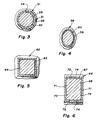
- an alternative manifold 58 is illustrated having oval runners 59 and flow control elements 60 of oval cross-section.
- a manifold 62 having runners 63 and flow control elements 64 of square or rectangular cross-section wherein the opposing surfaces form frustums of pyramids.
- FIG. 6 Another alternative configuration is shown in Figure 6 wherein a manifold 66 has runners 67 and flow control elements 68 of rectangular cross section.
- side surfaces 70, 7l, as shown in Figure 6, of the runners and control elements are parallel to one another and only upper and lower surfaces 72, 74 of the runners and elements converge in the direction of flow toward the cylinder.
- the inner surfaces of the runners and flow elements are wedge-shaped.
Landscapes
- Engineering & Computer Science (AREA)
- Chemical & Material Sciences (AREA)
- Combustion & Propulsion (AREA)
- Mechanical Engineering (AREA)
- General Engineering & Computer Science (AREA)
- Characterised By The Charging Evacuation (AREA)
- Cylinder Crankcases Of Internal Combustion Engines (AREA)
Claims (9)
- Moteur (10) à combustion interne, comprenant un orifice (18) d'admission de cylindre incluant une ouverture (19) de la chambre de combustion, et un système d'admission à aire variable raccordé à l'orifice (18) d'admission, ledit système d'admission à aire variable comprenant un passage (33) d'admission qui se raccorde au dit orifice (18) d'admission, ledit passage (33) d'admission ayant des parties de paroi présentant des surfaces intérieures convergentes (34), et un élément régulateur (39) de l'écoulement, qui est logé dans le passage (33) et possède des parties (40) de surface extérieure opposées aux dites surfaces intérieures convergentes (34) des parties de paroi du dit passage (33), l'élément (39) pouvant être déplacé dans le sens de l'écoulement du fluide vers l'orifice (18) et vers l'opposé de celui-ci, de manière à faire varier l'aire d'écoulement,
caractérisé en ce que ledit passage (33) d'admission comporte un tronçon raccordé au dit orifice (18) d'admission en amont de, mais étroitement adjacent à ladite ouverture (19) de la chambre de combustion; en ce que les surfaces intérieures (34) des parties de paroi du passage (33) d'admission convergent de façon continue les unes vers les autres sur toute la longueur du dit tronçon du passage (33) d'admission; en ce que lesdites parties (40) de surface extérieure de l'élément régulateur (39) de l'écoulaient sont maintenues de façon globalement parallèle aux dites surfaces intérieures convergentes (34) des parties de paroi du dit passage (33), pendant tout le mouvement de l'élément régulateur (39) de l'écoulement, de manière à définir une aire d'écoulement qui diminue de façon constante dans le sens de l'écoulement, l'aire étant comprise entre l'élément (39) et le passage (33) d'admission; et en ce que l'élément (39) peut être déplacé selon le sens d'écoulement du fluide vers un point dans l'orifice (18) d'admission, qui se situe près de l'ouverture (19) de la chambre de combustion, et vers l'opposé de ce point, de manière à faire varier l'aire d'écoulement et, de ce fait, la vitesse et l'inertie du flux de fluide vers l'ouverture (19) de la chambre de combustion. - Moteur à combustion interne selon la revendication 1, caractérisé en ce que ladite ouverture (19) de la chambre de combustion est commandée par une soupape champignon (23); et en ce que ledit passage (33) d'admission se raccorde à l'orifice (18) d'admission en amont de la soupape (23), et de façon étroitement adjacente à la tige (24) de la soupape (23).
- Moteur à combustion interne selon la revendication 1, caractérisé en ce que les surfaces opposées (34, 40) du passage (33) et de l'élément régulateur (39) présentent des sections latérales circulaires.
- Moteur à combustion interne selon la revendication 3, caractérisé en ce que les surfaces opposées (34, 40) du passage (33) et de l'élément régulateur (39) présentent une forme tronconique.
- Moteur à combustion interne selon la revendication 1, caractérisé en ce que les surfaces opposées du passage (59) et de l'élément régulateur (60) présentent des sections latérales ovales.
- Moteur à combustion interne selon la revendication 1, caractérisé en ce que les surfaces opposées du passage (63; 67) et de l'élément régulateur (64; 68) présentent des sections latérales rectangulaires.
- Moteur à combustion interne selon la revendication 6, caractérisé en ce que les surfaces opposées du passage (63) et de l'élément régulateur (64) définissent des troncs de pyramide.
- Moteur à combustion interne selon la revendication 6, caractérisé en ce que les surfaces opposées du passage (67) et de l'élément régulateur (68) présentent une forme de coin.
- Moteur à combustion interne selon l'une quelconque des revendications précédentes, caractérisé en ce que ledit système d'admission à aire variable comporte des moyens (42, 43, 44, 46, 47) pour déplacer l'élément régulateur (39) de manière à régler l'écoulement du fluide.
Applications Claiming Priority (2)
| Application Number | Priority Date | Filing Date | Title |
|---|---|---|---|
| US158967 | 1988-02-22 | ||
| US07/158,967 US4805573A (en) | 1988-02-22 | 1988-02-22 | Engine with variable area intake passages |
Publications (3)
| Publication Number | Publication Date |
|---|---|
| EP0330302A2 EP0330302A2 (fr) | 1989-08-30 |
| EP0330302A3 EP0330302A3 (en) | 1990-03-28 |
| EP0330302B1 true EP0330302B1 (fr) | 1992-09-16 |
Family
ID=22570511
Family Applications (1)
| Application Number | Title | Priority Date | Filing Date |
|---|---|---|---|
| EP89300360A Expired - Lifetime EP0330302B1 (fr) | 1988-02-22 | 1989-01-16 | Moteur avec passage d'admission à section variable |
Country Status (4)
| Country | Link |
|---|---|
| US (1) | US4805573A (fr) |
| EP (1) | EP0330302B1 (fr) |
| JP (1) | JPH01253526A (fr) |
| DE (1) | DE68902847D1 (fr) |
Families Citing this family (28)
| Publication number | Priority date | Publication date | Assignee | Title |
|---|---|---|---|---|
| JP2518930B2 (ja) * | 1989-07-24 | 1996-07-31 | 日産自動車株式会社 | 内燃機関の吸気装置 |
| US4964384A (en) * | 1989-08-31 | 1990-10-23 | Getz Carl M | Tornado engine |
| US4977866A (en) * | 1990-03-21 | 1990-12-18 | Don Wilkins | Flow control system for intake manifold |
| JP3421731B2 (ja) * | 1994-05-31 | 2003-06-30 | ヤマハ発動機株式会社 | エンジンの吸気制御装置 |
| JP3304751B2 (ja) * | 1996-03-29 | 2002-07-22 | トヨタ自動車株式会社 | 内燃機関の吸気通路構造 |
| DE19948660A1 (de) * | 1999-10-08 | 2001-04-12 | Mann & Hummel Filter | Ansaugvorrichtung |
| DE10128785A1 (de) * | 2001-06-13 | 2002-12-19 | Bayerische Motoren Werke Ag | Gemischaufbereitungsvorrichtung für einen Verbrennungsmotor |
| CN1668831A (zh) * | 2002-07-19 | 2005-09-14 | 利滕斯汽车公司 | 具有可变化横截面积的进气岐管 |
| CA2418133C (fr) * | 2003-02-07 | 2005-10-25 | Patrick Laneuville | Deflecteur d'entree d'air pour carburateurs double corps |
| US7073473B2 (en) * | 2003-07-18 | 2006-07-11 | Litens Automotive Partnership | Intake manifold variable runner area |
| US6986333B2 (en) * | 2004-05-25 | 2006-01-17 | Litens Automotive | Intake manifold with variable runner area |
| US7107962B1 (en) * | 2004-10-27 | 2006-09-19 | Accessible Technologies, Inc. | Carburetor hat for forced induction system |
| US7263970B2 (en) * | 2005-01-21 | 2007-09-04 | Honda Motor Co., Ltd. | Intake flow control apparatus for an internal combustion engine |
| FR2892768B1 (fr) * | 2005-10-27 | 2010-07-30 | Peugeot Citroen Automobiles Sa | Dispositif de reglage du debit d'un gaz dans une tubulure, notamment de reglage d'air dans une tubulure d'admission communiquant avec une chambre de combustion d'un moteur a combustion interne |
| JP2007127196A (ja) * | 2005-11-04 | 2007-05-24 | Denso Corp | トルク伝達装置 |
| KR100820709B1 (ko) * | 2006-12-05 | 2008-04-11 | 현대자동차주식회사 | 차량용 엔진의 흡기 매니폴드의 구조 |
| US7302930B1 (en) | 2006-12-13 | 2007-12-04 | Chrysler Llc | Air induction system and assembly method for an intake manifold with a single shaft and sensor for activating air control valves |
| US7556019B2 (en) * | 2006-12-15 | 2009-07-07 | Briggs And Stratton Corporation | Intake manifold regulators for internal combustion engines |
| US8074625B2 (en) | 2008-01-07 | 2011-12-13 | Mcalister Technologies, Llc | Fuel injector actuator assemblies and associated methods of use and manufacture |
| US8151774B2 (en) * | 2009-05-13 | 2012-04-10 | Deere & Company | Engine combustion air cyclonic pre-cleaner embodying throttling member adjusted in accordance with engine load |
| US7975669B2 (en) * | 2009-07-28 | 2011-07-12 | GM Global Technology Operations LLC | Apparatus and method for throttle control of internal combustion engines |
| US9038591B2 (en) | 2012-10-10 | 2015-05-26 | Fca Us Llc | Intake air control system for multi-cylinder combustion engine |
| US9309846B2 (en) | 2012-11-12 | 2016-04-12 | Mcalister Technologies, Llc | Motion modifiers for fuel injection systems |
| US20140131466A1 (en) | 2012-11-12 | 2014-05-15 | Advanced Green Innovations, LLC | Hydraulic displacement amplifiers for fuel injectors |
| CN103266968B (zh) * | 2013-05-06 | 2015-07-01 | 中国第一汽车股份有限公司无锡油泵油嘴研究所 | 一种实现大egr率的调节装置 |
| US9689334B2 (en) | 2014-11-14 | 2017-06-27 | Cnh Industrial America Llc | Air intake system for an off-road vehicle |
| WO2019000022A1 (fr) * | 2017-06-27 | 2019-01-03 | Parle Technologies Pty Ltd | Admission de moteur |
| CN113202635A (zh) * | 2021-05-20 | 2021-08-03 | 重庆隆鑫机车有限公司 | 节气门阀体及发动机 |
Family Cites Families (10)
| Publication number | Priority date | Publication date | Assignee | Title |
|---|---|---|---|---|
| FR1189338A (fr) * | 1957-12-30 | 1959-10-01 | Simca Automobiles Sa | Dispositif de réglage d'admission de fluide gazeux en veine homogène |
| GB1175792A (en) * | 1967-05-20 | 1969-12-23 | Porsche K G | An Internal Combustion Engine having an Adjustable Air Inlet Connection |
| US3557762A (en) * | 1969-02-06 | 1971-01-26 | Gen Motors Corp | Engine with variable opening inlet valve means |
| DE2334183A1 (de) * | 1973-07-05 | 1975-01-23 | Audi Nsu Auto Union Ag | Rotationskolben-brennkraftmaschine in trochoidenbauart |
| US3875918A (en) * | 1973-08-08 | 1975-04-08 | Richard S Loynd | Variable area intake manifold for internal combustion |
| US4210107A (en) * | 1977-01-18 | 1980-07-01 | Shaffer Donald J | Tuneable intake manifold |
| US4228772A (en) * | 1979-02-01 | 1980-10-21 | General Motors Corporation | Low throttled volume engine |
| US4539947A (en) * | 1982-12-09 | 1985-09-10 | Nippondenso Co., Ltd. | Resonator for internal combustion engines |
| DE3518684A1 (de) * | 1985-05-24 | 1986-11-27 | Audi AG, 8070 Ingolstadt | Saugrohr fuer eine mehrzylindrige brennkraftmaschine |
| DE3626681A1 (de) * | 1986-06-26 | 1988-01-14 | Arne Dipl Ing Walde | Vorrichtung zur steuerung der luft- und/oder kraftstoffmenge in verbrennungskraftmaschinen |
-
1988
- 1988-02-22 US US07/158,967 patent/US4805573A/en not_active Expired - Fee Related
-
1989
- 1989-01-16 DE DE8989300360T patent/DE68902847D1/de not_active Expired - Lifetime
- 1989-01-16 EP EP89300360A patent/EP0330302B1/fr not_active Expired - Lifetime
- 1989-02-22 JP JP1042923A patent/JPH01253526A/ja active Pending
Also Published As
| Publication number | Publication date |
|---|---|
| US4805573A (en) | 1989-02-21 |
| JPH01253526A (ja) | 1989-10-09 |
| DE68902847D1 (de) | 1992-10-22 |
| EP0330302A2 (fr) | 1989-08-30 |
| EP0330302A3 (en) | 1990-03-28 |
Similar Documents
| Publication | Publication Date | Title |
|---|---|---|
| US4805573A (en) | Engine with variable area intake passages | |
| US4763612A (en) | Intake system for internal combustion engine | |
| US4617896A (en) | Internal combustion engine having three intake valves per cylinder | |
| US4726337A (en) | Intake system for multiple intake valve type engines | |
| US4766853A (en) | Intake passage for multi-cylinder engine | |
| US4809647A (en) | Intake system for multi cylindered engine | |
| US4253432A (en) | Intake system of an internal combustion engine of a counter-flow type | |
| US5000131A (en) | Exhaust port control valve for two stroke engine | |
| US4702203A (en) | Intake means of internal combustion engine | |
| US4765285A (en) | Intake system for internal combustion engine | |
| EP0703355B1 (fr) | Moteur à combustion interne | |
| US5515822A (en) | Intake system | |
| US5009200A (en) | Intake manifold assembly for a multicylinder internal combustion engine | |
| US4630446A (en) | Outboard motor with turbo-charger | |
| US4488531A (en) | Plural intake system for supercharged engine | |
| US4566422A (en) | Fuel intake system for a supercharged engine | |
| US4867109A (en) | Intake passage arrangement for internal combustion engines | |
| CA1195567A (fr) | Methode et dispositif d'alimentation d'un moteur a combustion interne en carburant | |
| US4726340A (en) | Intake system for multi-cylinder engine | |
| US5487365A (en) | Induction system for engine | |
| US4727829A (en) | Intake system for internal combustion engine | |
| EP0321033B1 (fr) | Dispositif d'admission pour moteur à combustion interne à plusieurs cylindres | |
| US5572965A (en) | Intake pipe for internal combustion engine | |
| US4898144A (en) | Intake system for internal combustion engine | |
| US6408809B2 (en) | Intake control device for multi-cylinder V-type engine |
Legal Events
| Date | Code | Title | Description |
|---|---|---|---|
| PUAI | Public reference made under article 153(3) epc to a published international application that has entered the european phase |
Free format text: ORIGINAL CODE: 0009012 |
|
| AK | Designated contracting states |
Kind code of ref document: A2 Designated state(s): DE FR GB IT |
|
| PUAL | Search report despatched |
Free format text: ORIGINAL CODE: 0009013 |
|
| AK | Designated contracting states |
Kind code of ref document: A3 Designated state(s): DE FR GB IT |
|
| 17P | Request for examination filed |
Effective date: 19900504 |
|
| 17Q | First examination report despatched |
Effective date: 19910405 |
|
| GRAA | (expected) grant |
Free format text: ORIGINAL CODE: 0009210 |
|
| AK | Designated contracting states |
Kind code of ref document: B1 Designated state(s): DE FR GB IT |
|
| PG25 | Lapsed in a contracting state [announced via postgrant information from national office to epo] |
Ref country code: IT Free format text: LAPSE BECAUSE OF FAILURE TO SUBMIT A TRANSLATION OF THE DESCRIPTION OR TO PAY THE FEE WITHIN THE PRESCRIBED TIME-LIMIT;WARNING: LAPSES OF ITALIAN PATENTS WITH EFFECTIVE DATE BEFORE 2007 MAY HAVE OCCURRED AT ANY TIME BEFORE 2007. THE CORRECT EFFECTIVE DATE MAY BE DIFFERENT FROM THE ONE RECORDED. Effective date: 19920916 Ref country code: FR Effective date: 19920916 Ref country code: DE Effective date: 19920916 |
|
| REF | Corresponds to: |
Ref document number: 68902847 Country of ref document: DE Date of ref document: 19921022 |
|
| PG25 | Lapsed in a contracting state [announced via postgrant information from national office to epo] |
Ref country code: GB Effective date: 19930116 |
|
| EN | Fr: translation not filed | ||
| PLBE | No opposition filed within time limit |
Free format text: ORIGINAL CODE: 0009261 |
|
| STAA | Information on the status of an ep patent application or granted ep patent |
Free format text: STATUS: NO OPPOSITION FILED WITHIN TIME LIMIT |
|
| 26N | No opposition filed | ||
| GBPC | Gb: european patent ceased through non-payment of renewal fee |
Effective date: 19930116 |