EP0330336A2 - Röntgenquelle hoher Intensität unter Verwendung eines Balgs - Google Patents
Röntgenquelle hoher Intensität unter Verwendung eines Balgs Download PDFInfo
- Publication number
- EP0330336A2 EP0330336A2 EP89301215A EP89301215A EP0330336A2 EP 0330336 A2 EP0330336 A2 EP 0330336A2 EP 89301215 A EP89301215 A EP 89301215A EP 89301215 A EP89301215 A EP 89301215A EP 0330336 A2 EP0330336 A2 EP 0330336A2
- Authority
- EP
- European Patent Office
- Prior art keywords
- cathode
- anode
- axis
- tube
- vacuum chamber
- Prior art date
- Legal status (The legal status is an assumption and is not a legal conclusion. Google has not performed a legal analysis and makes no representation as to the accuracy of the status listed.)
- Granted
Links
Images


Classifications
-
- H—ELECTRICITY
- H05—ELECTRIC TECHNIQUES NOT OTHERWISE PROVIDED FOR
- H05G—X-RAY TECHNIQUE
- H05G1/00—X-ray apparatus involving X-ray tubes; Circuits therefor
- H05G1/02—Constructional details
- H05G1/04—Mounting the X-ray tube within a closed housing
-
- H—ELECTRICITY
- H01—ELECTRIC ELEMENTS
- H01J—ELECTRIC DISCHARGE TUBES OR DISCHARGE LAMPS
- H01J35/00—X-ray tubes
- H01J35/02—Details
- H01J35/04—Electrodes ; Mutual position thereof; Constructional adaptations therefor
- H01J35/08—Anodes; Anti cathodes
- H01J35/10—Rotary anodes; Arrangements for rotating anodes; Cooling rotary anodes
-
- H—ELECTRICITY
- H01—ELECTRIC ELEMENTS
- H01J—ELECTRIC DISCHARGE TUBES OR DISCHARGE LAMPS
- H01J35/00—X-ray tubes
- H01J35/02—Details
- H01J35/16—Vessels; Containers; Shields associated therewith
-
- H—ELECTRICITY
- H01—ELECTRIC ELEMENTS
- H01J—ELECTRIC DISCHARGE TUBES OR DISCHARGE LAMPS
- H01J35/00—X-ray tubes
- H01J35/24—Tubes wherein the point of impact of the cathode ray on the anode or anticathode is movable relative to the surface thereof
- H01J35/26—Tubes wherein the point of impact of the cathode ray on the anode or anticathode is movable relative to the surface thereof by rotation of the anode or anticathode
-
- H—ELECTRICITY
- H05—ELECTRIC TECHNIQUES NOT OTHERWISE PROVIDED FOR
- H05G—X-RAY TECHNIQUE
- H05G1/00—X-ray apparatus involving X-ray tubes; Circuits therefor
- H05G1/02—Constructional details
- H05G1/025—Means for cooling the X-ray tube or the generator
-
- H—ELECTRICITY
- H01—ELECTRIC ELEMENTS
- H01J—ELECTRIC DISCHARGE TUBES OR DISCHARGE LAMPS
- H01J2235/00—X-ray tubes
- H01J2235/16—Vessels
- H01J2235/161—Non-stationary vessels
- H01J2235/162—Rotation
Definitions
- This invention pertains to a high intensity source of X-rays using a fluid cooled rotating anode, more particularly to a source incorporating a bellows to accommodate relative motions of the cathodes and anode.
- the classic X-ray tubes have a thermionic cathode at one end and a fixed anode at the other end. Electrons emitted from the cathode are accelerated by a high potential and impact the anode thereby producing X-rays.
- the electron beam which must be tightly focused to produce a high-definition image, produces extreme heating of the anode target. The power capability of this tube is limited by the conductive cooling of the anode target.
- High intensity X-ray sources are in increasing demand for applications such as X-ray Lithography for Producing Integrated Circuits, Computerized Tomography for X-ray Imaging, and for X-ray Diffraction for Analyzing Materials.
- High intensity X-ray sources can be constructed by impinging a high intensity beam of electrons on an anode, but cooling the anode becomes a significant technical problem.
- a latter advance was the rotating-target tube in which the target is the surface of a metal disk spinning rapidly on bearings inside the vacuum envelope and driven by the rotor of an electric induction motor whose stator is outside the envelope.
- the rotating anode spreads the heat over an annular area of the target and provides much higher power for a short operating time, as in medical radiography.
- the ultimate cooling of the anode is mostly by thermal radiation in the high vacuum, so these tubes are inadequate for heavy duty operation. One has to wait for the massive anode to slowly cool.
- U.S. Patent 1,160,177 to Kelley discloses an X-ray which uses an externally applied cooling medium with a fixed anode. Some improvement in distributing the heat from the beam can be achieved by steering the electron beam to different parts of the anode.
- U.S. Patent 2,229,152 to Walsweer and U.S. Patent 4,336,476 to Holland disclose an anode sealed entirely in the vacuum which rotates in response to the field from coils exterior to the vacuum. The heat from the anode must be conducted through bearings irradiated through the vacuum to an external cap.
- U.S. Patent 4,128,781 to Flisikowski et al. discloses an X-ray tube having a cathode rotatable relative to an anode.
- Electrons from a rotating cathode are incident on a stationary anode ring.
- the X-rays are emitted from different positions in space as a cathode is rotated. For most applications it is important that the X-rays be emitted from a fixed position in space.
- EP-A-0 187 020 describes methods by which the anode is rotated while the cathode is operationally fixed in space.
- One method is to have the rotating thermionic cathode emit along the axis of rotation and the electron beam is deflected by a stationary magnetic field to a stationary spot on the rotating anode.
- the cathode is held stationary off axis by hanging on bearings from the rotating envelope and being held stationary by a magnetic or gravitational field.
- EP - A - 0 187 020 describes an X-ray tube having the whole vacuum envelope rotate with the anode.
- the anode being part of the vacuum envelope, it can be cooled from the outside by liquid or air.
- the cathode also rotates. It is an axially symmetric band of photocathode surface which is illuminated by a focused, stationary spot of light entering the envelope through an auxiliary symmetric transparent window, part of the vacuum envelope. Photoelectrons from the cathode are focused, as by a stationary magnetic field, onto a small stationary spot through which the anode rotates.
- a high power X-ray tube can be designed to dissipate the heat over a large area of anode.
- nearly all involve a rotating seal in the form of a sliding O-ring seal or a Ferrofluidic seal. These seals cause problems by limiting the rotation speed or life of the tube due to seal failure.
- an X-ray tube as set out in Claim 1.
- the cathode is preferably mounted on a cylindrically symmetric shaft which is supported by a pair of bearings outside the vacuum chamber.
- slip rings may be included on the shaft and contact means may be provided for transmitting current to a cathode heater, the slip rings and contact means being located outside the vacuum chamber.
- the anode may be so mounted.
- the bellows is preferably generally disposed around the shaft.
- the cathode When the second axis intersects the first axis at an angle, the cathode is preferably rotatably mounted by a first bearing co-axially arranged in space with the first axis, the cathode being constrained by a second bearing mounted co-axially with the second axis whereby the cathode is constrained to maintain a fixed position with respect to the frame.
- This arrangement may also be applied to the tube when the first and second axes are parallel.
- a vacuum enclosing shell 10 including an anode support 12, a window 14, an insulating cylinder 16, the cathode support 17, a bellows 18, and a cathode stabilizer 20. These parts can all be hard soldered or brazed together such that the enclosed volume can be pumped out and maintained under high vacuum conditions.
- a motor 22 rotates this whole shell 10 at a high angular speed of several thousand RPM's. As shown, the motor 22 supports one end of this structure through the insulating coupling 24 and the other end is supported by shell bearings 26 which have a rotational axis A2 common to that of the motor 22.
- internal bearings 28 are aligned on the same axis so that the internal cathode can be maintained at a fixed position as the shell rotates.
- the cathode is constrained from rotating by the cathode stabilizer 20 on the axis A1 which is offset from the motor axis A2.
- the two axes A1 and A2 are shown parallel to each other.
- the cathode stabilizer axis may also be tilted with respect to the motor axis and so long as the cathode stabilizer bearings 32 and 33 are properly supported and maintain a common axis with each other.
- a transformer with a primary 36 outside of the rotating shell is magnetically coupled through the insulating cylinder 16 to the secondary 38 of the transformer which is attached to the stationary cathode 39 member inside of the rotating shell 10. Power is thereby coupled from the outside to the interior cathode structure.
- the positive high voltage is applied to the anode support 12 by a slip ring 40 on the driving shaft. This voltage may be insulated from the motor by the insulating mechanical coupling 24.
- the negative supply may be coupled to the cathode through another slip ring or through bearings 26 and 28 or through bearings 32 and 33.
- the cathode stabilizer 20 rotates along with the rest of the structure, its axis is fixed with respect to the base and does not coincide with the motor axis.
- the internal cathode support 42 is constrained from rotating by its contact with the cathode stabilizer 20.
- the cathode 34 is stationary with respect to the motor 22 so that the electron beam pattern provided can be rectangularly shaped if desired, permitting the bombardment pattern on the anode 44 also to be in the form a rectangle with the long axis along the radial direction.
- This technique is used in order to spread the heat out along the radial direction of the anode 44 and thereby reduce the instantaneous heat load to the anode 44 and still obtain the small X-ray spot size.
- the motor 22, stabilizer bearings 32 and primary 36 are all mounted on a base 46.
- FIG. 2 Another X-ray tube configuration is sketched in Fig. 2. This configuration is much like that of Fig. 1 except the cathode 134 is directly attached to the cathode support member 136.
- the electrical power leads for the heater are coupled to the region outside the vacuum and to the power supply 138 through a standard vacuum feedthrough 140 and then coupled to the external heater current source through a pair of slip rings 142. Since the cathode 134 itself rotates relative to the anode in this configuration, one must use a cathode geometry that emits a circular electron beam pattern so that the X-ray pattern will be independent of the angular position of the cathode 134 or anode 144.
- Figure 3 shows a third configuration where the bellows 218 are used on the anode side of the tube rather than the cathode side.
- This permits the use of a small circular X-ray window 214.
- the cathode is in the form of a circle that surrounds the X-ray window 214.
- the electrons form a converging cone that is incident upon the anode 244.
- a V-groove anode configuration may be used. The V-groove permits a spreading of the instantaneous electron heating over a larger anode surface area.
- the X-rays are extracted through the X-ray window 214 so they leave the anode 244 surface at approximately the same angle that the electrons arrived permitting the proper foreshortening of the X-ray spot size.
- the V-groove geometry also permits a more symmetric distribution of the X-ray intensity and energies making this configuration a good candidate as a source for X-ray lithography.
- feedthroughs are used in order to couple the heater current to the external world and slip rings are used to couple the current to the filament current source.
- the X-ray anode 244 is contained almost completely within the vacuum enclosure 210.
- a liquid coolant within the anode structure may be readily cooled by circulating a liquid coolant within the anode structure by bringing the liquid in and out through channels in the drive shaft.
- the coolant gland 246 permits one to circulate the fluid through an external heat exchanger.
- an insulating coupling can be used as in Fig. 1 to electrically isolate the motor from the X-ray anode. Electrically insulating coolants should be used whenever the anode is not grounded. No internal bearings are contained in the embodiments shown in Figs. 2 and 3 so that the vacuum bearing problems of prior rotating-anode X-ray tubes are eliminated.
- Figs. 1 and 2 a cylindrical window is shown that traverses the entire circumference of the vacuum cylinder. In practice, this window may just be part of the insulating cylinder as materials such as alumina have low loss to X-rays as well as good insulating properties. Another question deals with the choice of coolant and the exact cooling configuration.
- the present generation of rotating anode X-ray tubes for medical use have balanced power supplies with the anode positive with respect to ground and the cathode negative with respect to ground.
- Fig. 4 an embodiment similar to that disclosed in Fig. 1.
- the bellows arrangement is slightly different, requiring only a single twist of the bellows as opposed to a double twist.
- the advantage of this arrangement is that for a given offset, one provides less stress to the bellows, and results in longer bellow lifetimes.
- a shaft extends through the bearings 310 and 314 that support the cathode and bends to follow the contour of the bellows.
- a spring-loaded ball contact that locks the cathode in place so that it does not rotate and provides the dc path for the anode to cathode current.
- heater current is provided by a thru-the-wall transformer that magnetically couples ac power from the region outside of the rotating ceramic cylinder to the inside coil which in turn is connected to the cathode heater.
- Figure 4 also shows a way of cooling the backside of the anode which was not explicitly shown in any of the embodiments above.
- Several cooling arrangements were shown in an earlier disclosure which has now been filed as U.S. Patent Application, Serial No. 06/683,982.
- the tube of FIG. 4 has a rotating glass or ceramic insulator 300, a fixed cathode 302 and a rotating anode 304.
- the cathode 302 is mounted on a cathode support 306 which is attached to a fixed shaft 308.
- a first set of two bearings 310 allow the shaft 308 to remain fixed while the bearing support 312 rotates around it.
- a second set of two bearings 314 separates the rotating bearing support 312 from the support frame 316.
- a sealing ring 318 at both ends provide a glass-to-metal seal.
- the bearing support 312 is also sealed to the bellows 320. An opposite end of the bellows is sealed to the end cap 322.
- FIG. 5 shows additional detail of the anode end of the tube of FIG. 4.
- the rotating glass insulator 300 is attached to the anode 304 with a second sealing ring 318.
- the anode 304 is attached to an insulating ring 334 made of a suitable plastic or ceramic insulator.
- a stator 336, supported by the shaft 338 is used to divert coolant around the inside of the anode to achieve maximum cooling efficiency.
- the shaft 338 is kept from rotating by attachment of the coolant manifold 370 at its end to the support frame 316.
- Within the shaft 338 there are passages for inflow 340 and outflow 342 of coolant to the anode 304.
- a rod 344 down the center of the shaft 338 maintains positive electric potential on the anode 304 via a spring-loaded ball 346.
- An O-ring 347 provides a coolant seal between the insulating ring 334 and the back of the anode 304.
- a metal ring 348 attached to the outside end of the insulating ring 334 has a graphite face 350. The metal ring 348 and graphite face 350 are part of the rotating assembly.
- a stationary lapped silicon carbide ring 352 is in sliding contact with the graphite face 350 to provide a rotating water-tight seal.
- a seal between the ring 352 and the shaft 338 is provided with an O-ring 354 compressed by collar 356.
- a cylindrical bearing support ring 358 is mechanically attached to both the ring 348 and the insulating ring 334.
- An O-ring 359 provides the coolant seal between metal ring 348 and insulating ring 334.
- the cylindrical bearing support ring 358 is isolated from the frame 316 with a pair of bearings 360.
- a pulley 362 is also attached to the cylindrical bearing support ring 358 between the pair of bearings 360.
- a belt 364 driven by a drive pulley 366 and motor 368 is used to drive the pulley 362 and the anode assembly.
- a coolant manifold 370 is used to distribute the coolant and support the shaft 338.
- An insulating plate 372 is attached to the insulating ring 334 to prevent arcing between the sealing ring 318 and parts of the frame 316.
- a single turn secondary coil 374 attached to the cathode support 306 is used to power the heater for the cathode.
- the primary 376 located outside the tube is concentric with the secondary and operates at 13.56 MHz.
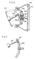
- the cathode assembly 400 is mounted via a shaft 402 and pair of bearings 404 to an internal support 406.
- a cathode positioner 408 is held fixed in space by a shaft 410 having a spring-loaded bearing 412.
- the shaft 410 rotates with the bellows 414 which is attached to the rotating insulator 418 and anode as in the previous embodiment.
- the cathode 416 is fixed in space and decoupled from the motion of the shaft 410 by the bearing 412.
- the shaft 410 is replaced by the shaft 420 and the cathode positioner 408 is replaced by the cathode positioner 424.
- the functions of the shaft and cathode positioner remain the same, but a ring bearing 422 fitted into the cathode positioner 424 provides for relative rotation of the rod 420.
- bellows used in such a tube must be compatible with bakeout in a high vacuum environment and with continuous flexure during rotation.
- Such bellows are generally stainless steel or inconel bellows with welded joints at flexure points.
Landscapes
- X-Ray Techniques (AREA)
Applications Claiming Priority (2)
| Application Number | Priority Date | Filing Date | Title |
|---|---|---|---|
| US07/160,223 US4878235A (en) | 1988-02-25 | 1988-02-25 | High intensity x-ray source using bellows |
| US160223 | 1988-02-25 |
Publications (3)
| Publication Number | Publication Date |
|---|---|
| EP0330336A2 true EP0330336A2 (de) | 1989-08-30 |
| EP0330336A3 EP0330336A3 (en) | 1989-11-15 |
| EP0330336B1 EP0330336B1 (de) | 1994-04-06 |
Family
ID=22576026
Family Applications (1)
| Application Number | Title | Priority Date | Filing Date |
|---|---|---|---|
| EP89301215A Expired - Lifetime EP0330336B1 (de) | 1988-02-25 | 1989-02-08 | Röntgenquelle hoher Intensität unter Verwendung eines Balgs |
Country Status (6)
| Country | Link |
|---|---|
| US (1) | US4878235A (de) |
| EP (1) | EP0330336B1 (de) |
| JP (1) | JP2753566B2 (de) |
| CA (1) | CA1311011C (de) |
| DE (1) | DE68914307T2 (de) |
| IL (1) | IL89236A (de) |
Cited By (4)
| Publication number | Priority date | Publication date | Assignee | Title |
|---|---|---|---|---|
| EP0377534A1 (de) * | 1989-01-06 | 1990-07-11 | Yehuda Elyada | Röntgenröhrevorrichtung |
| US5086442A (en) * | 1990-03-28 | 1992-02-04 | Siemens Aktiengesellschaft | Magnetic coupling for a rotating X-ray tube |
| EP0810815A1 (de) * | 1996-05-29 | 1997-12-03 | Philips Patentverwaltung GmbH | Röntgeneinrichtung |
| DE10353964A1 (de) * | 2003-11-19 | 2005-06-02 | Siemens Ag | Röntgenröhre mit Drehanode |
Families Citing this family (17)
| Publication number | Priority date | Publication date | Assignee | Title |
|---|---|---|---|---|
| DE4004013A1 (de) * | 1990-02-09 | 1991-08-14 | Siemens Ag | Roentgen-drehroehre |
| US5200985A (en) * | 1992-01-06 | 1993-04-06 | Picker International, Inc. | X-ray tube with capacitively coupled filament drive |
| US5241577A (en) * | 1992-01-06 | 1993-08-31 | Picker International, Inc. | X-ray tube with bearing slip ring |
| US5384820A (en) * | 1992-01-06 | 1995-01-24 | Picker International, Inc. | Journal bearing and radiation shield for rotating housing and anode/stationary cathode X-ray tubes |
| US5581591A (en) * | 1992-01-06 | 1996-12-03 | Picker International, Inc. | Focal spot motion control for rotating housing and anode/stationary cathode X-ray tubes |
| EP0550983B1 (de) * | 1992-01-06 | 1996-08-28 | Picker International, Inc. | Röntgenröhre mit Ferritkern-Glühwendeltransformator |
| US5274690A (en) * | 1992-01-06 | 1993-12-28 | Picker International, Inc. | Rotating housing and anode/stationary cathode x-ray tube with magnetic susceptor for holding the cathode stationary |
| US5550890A (en) * | 1995-06-06 | 1996-08-27 | Anderson; Weston A. | Magnetically supported cathode X-ray source |
| US5978448A (en) * | 1998-01-21 | 1999-11-02 | General Electric Company | Bearing preload arrangement with linear bearing component for X-ray tube |
| US6144720A (en) * | 1998-08-28 | 2000-11-07 | Picker International, Inc. | Iron oxide coating for x-ray tube rotors |
| US6249569B1 (en) * | 1998-12-22 | 2001-06-19 | General Electric Company | X-ray tube having increased cooling capabilities |
| US6944270B1 (en) * | 2004-02-26 | 2005-09-13 | Osmic, Inc. | X-ray source |
| JP3836855B2 (ja) * | 2004-07-15 | 2006-10-25 | 株式会社リガク | 回転対陰極x線管及びx線発生装置 |
| US7502446B2 (en) * | 2005-10-18 | 2009-03-10 | Alft Inc. | Soft x-ray generator |
| US20100128848A1 (en) * | 2008-11-21 | 2010-05-27 | General Electric Company | X-ray tube having liquid lubricated bearings and liquid cooled target |
| US9032735B2 (en) | 2012-04-26 | 2015-05-19 | General Electric Company | Combustor and a method for assembling the combustor |
| JP6677420B2 (ja) * | 2016-04-01 | 2020-04-08 | キヤノン電子管デバイス株式会社 | X線管装置 |
Family Cites Families (22)
| Publication number | Priority date | Publication date | Assignee | Title |
|---|---|---|---|---|
| US1160177A (en) * | 1914-06-27 | 1915-11-16 | Snook Roentgen Mfg Company | X-ray tube. |
| US2209963A (en) * | 1938-06-18 | 1940-08-06 | California Inst Of Techn | X-ray generating device |
| US2229152A (en) * | 1938-09-21 | 1941-01-21 | Westinghouse Electric & Mfg Co | Rotary anode X-ray tube |
| US2290226A (en) * | 1940-12-19 | 1942-07-21 | Mond Jesse W M Du | X-ray generating device |
| GB640694A (en) * | 1945-06-11 | 1950-07-26 | Frank Waterton | Improvements in x-ray apparatus |
| US2790102A (en) * | 1955-10-04 | 1957-04-23 | Dunlee Corp | X-ray tube anode |
| US2926270A (en) * | 1957-12-30 | 1960-02-23 | Gen Electric | Rotating anode x-ray tube |
| US3230409A (en) * | 1962-01-03 | 1966-01-18 | High Voltage Engineering Corp | Rotatable charged particle beam deflector |
| US3331978A (en) * | 1962-05-28 | 1967-07-18 | Varian Associates | Electron beam x-ray generator with movable, fluid-cooled target |
| US3303372A (en) * | 1964-08-20 | 1967-02-07 | Dunlee Corp | X-ray generator with a knife edged cold cathode emitter |
| US3619696A (en) * | 1969-11-17 | 1971-11-09 | Torr Lab Inc | An electric drive motor for rotatably driving the anode of an x-ray tube |
| US3735175A (en) * | 1971-03-15 | 1973-05-22 | Inter Probe | Method and apparatus for removing heat from within a vacuum and from within a mass |
| US3689790A (en) * | 1971-04-29 | 1972-09-05 | Pepi Inc | Moving target sealed x-ray tube |
| US3737698A (en) * | 1971-11-24 | 1973-06-05 | F Carter | X-ray target changer using a translating anode |
| US3753020A (en) * | 1971-11-26 | 1973-08-14 | Philips Electronics And Pharm | Multi-anode x-ray tube |
| US3794872A (en) * | 1972-06-21 | 1974-02-26 | D Haas | Moving target spring loaded x-ray tube |
| DE2607618A1 (de) * | 1976-02-25 | 1977-09-01 | Philips Patentverwaltung | Roentgenroehre |
| US4336476A (en) * | 1978-09-05 | 1982-06-22 | The Machlett Laboratories, Incorporated | Grooved X-ray generator |
| DE3043046A1 (de) * | 1980-11-14 | 1982-07-15 | Siemens AG, 1000 Berlin und 8000 München | Drehanoden-roentgenroehre |
| FR2548829B1 (fr) * | 1983-07-06 | 1985-11-22 | Thomson Csf | Tube a rayons x a anode tournante muni d'un dispositif d'ecoulement des charges |
| FR2563436B1 (fr) * | 1984-04-26 | 1987-06-12 | Taddei Andre | Dispositif a seringue d'injection ster ile, notamment pour les dentistes |
| JP2539193B2 (ja) * | 1984-12-20 | 1996-10-02 | バリアン・アソシエイツ・インコーポレイテッド | 高強度x線源 |
-
1988
- 1988-02-25 US US07/160,223 patent/US4878235A/en not_active Expired - Lifetime
-
1989
- 1989-02-08 DE DE68914307T patent/DE68914307T2/de not_active Expired - Fee Related
- 1989-02-08 EP EP89301215A patent/EP0330336B1/de not_active Expired - Lifetime
- 1989-02-09 IL IL89236A patent/IL89236A/xx not_active IP Right Cessation
- 1989-02-23 JP JP1041953A patent/JP2753566B2/ja not_active Expired - Lifetime
- 1989-02-24 CA CA000592111A patent/CA1311011C/en not_active Expired - Lifetime
Cited By (6)
| Publication number | Priority date | Publication date | Assignee | Title |
|---|---|---|---|---|
| EP0377534A1 (de) * | 1989-01-06 | 1990-07-11 | Yehuda Elyada | Röntgenröhrevorrichtung |
| US5086442A (en) * | 1990-03-28 | 1992-02-04 | Siemens Aktiengesellschaft | Magnetic coupling for a rotating X-ray tube |
| EP0810815A1 (de) * | 1996-05-29 | 1997-12-03 | Philips Patentverwaltung GmbH | Röntgeneinrichtung |
| DE10353964A1 (de) * | 2003-11-19 | 2005-06-02 | Siemens Ag | Röntgenröhre mit Drehanode |
| US7116757B2 (en) | 2003-11-19 | 2006-10-03 | Siemens Aktiengesellschaft | X-ray tube with rotary anode |
| DE10353964B4 (de) * | 2003-11-19 | 2013-10-10 | Siemens Aktiengesellschaft | Röntgenröhre mit Drehanode |
Also Published As
| Publication number | Publication date |
|---|---|
| IL89236A0 (en) | 1989-09-10 |
| DE68914307D1 (de) | 1994-05-11 |
| DE68914307T2 (de) | 1994-07-14 |
| JP2753566B2 (ja) | 1998-05-20 |
| IL89236A (en) | 1992-09-06 |
| EP0330336A3 (en) | 1989-11-15 |
| US4878235A (en) | 1989-10-31 |
| JPH0210637A (ja) | 1990-01-16 |
| CA1311011C (en) | 1992-12-01 |
| EP0330336B1 (de) | 1994-04-06 |
Similar Documents
| Publication | Publication Date | Title |
|---|---|---|
| CA1311011C (en) | High intensity x-ray source using bellows | |
| US4788705A (en) | High-intensity X-ray source | |
| US4674109A (en) | Rotating anode x-ray tube device | |
| US5105456A (en) | High duty-cycle x-ray tube | |
| US4993055A (en) | Rotating X-ray tube with external bearings | |
| US5268955A (en) | Ring tube x-ray source | |
| EP0715333B1 (de) | Anordnung von Röntgenröhren | |
| US4821305A (en) | Photoelectric X-ray tube | |
| US6674838B1 (en) | X-ray tube having a unitary vacuum enclosure and housing | |
| EP0917176B1 (de) | Lageranordnung für eine Drehanoden-Röntgenröhre | |
| US6041100A (en) | Cooling device for x-ray tube bearing assembly | |
| US2290226A (en) | X-ray generating device | |
| JP4309290B2 (ja) | X線ターゲット用液体金属ヒートパイプ構造 | |
| US3689790A (en) | Moving target sealed x-ray tube | |
| US3794872A (en) | Moving target spring loaded x-ray tube | |
| US4128781A (en) | X-ray tube | |
| JP3030069B2 (ja) | X線管 | |
| US3619696A (en) | An electric drive motor for rotatably driving the anode of an x-ray tube | |
| US12597580B2 (en) | X-ray generating apparatus and imaging device | |
| US6453011B1 (en) | X-ray tube with rotating anode core | |
| WO1987006055A1 (en) | Photoelectric x-ray tube | |
| JPS61151956A (ja) | 回転陽極型x線管 | |
| JP2001325909A (ja) | 回転対陰極の電流還流機構 | |
| JPH0329125B2 (de) |
Legal Events
| Date | Code | Title | Description |
|---|---|---|---|
| PUAI | Public reference made under article 153(3) epc to a published international application that has entered the european phase |
Free format text: ORIGINAL CODE: 0009012 |
|
| AK | Designated contracting states |
Kind code of ref document: A2 Designated state(s): DE FR GB |
|
| PUAL | Search report despatched |
Free format text: ORIGINAL CODE: 0009013 |
|
| AK | Designated contracting states |
Kind code of ref document: A3 Designated state(s): DE FR GB |
|
| 17P | Request for examination filed |
Effective date: 19900502 |
|
| 17Q | First examination report despatched |
Effective date: 19920701 |
|
| GRAA | (expected) grant |
Free format text: ORIGINAL CODE: 0009210 |
|
| AK | Designated contracting states |
Kind code of ref document: B1 Designated state(s): DE FR GB |
|
| REF | Corresponds to: |
Ref document number: 68914307 Country of ref document: DE Date of ref document: 19940511 |
|
| REG | Reference to a national code |
Ref country code: GB Ref legal event code: 746 Effective date: 19940421 |
|
| ET | Fr: translation filed | ||
| REG | Reference to a national code |
Ref country code: FR Ref legal event code: DL |
|
| PLBE | No opposition filed within time limit |
Free format text: ORIGINAL CODE: 0009261 |
|
| STAA | Information on the status of an ep patent application or granted ep patent |
Free format text: STATUS: NO OPPOSITION FILED WITHIN TIME LIMIT |
|
| 26N | No opposition filed | ||
| REG | Reference to a national code |
Ref country code: GB Ref legal event code: IF02 |
|
| PGFP | Annual fee paid to national office [announced via postgrant information from national office to epo] |
Ref country code: FR Payment date: 20020117 Year of fee payment: 14 |
|
| PGFP | Annual fee paid to national office [announced via postgrant information from national office to epo] |
Ref country code: DE Payment date: 20020118 Year of fee payment: 14 |
|
| PGFP | Annual fee paid to national office [announced via postgrant information from national office to epo] |
Ref country code: GB Payment date: 20020121 Year of fee payment: 14 |
|
| PG25 | Lapsed in a contracting state [announced via postgrant information from national office to epo] |
Ref country code: GB Free format text: LAPSE BECAUSE OF NON-PAYMENT OF DUE FEES Effective date: 20030208 |
|
| PG25 | Lapsed in a contracting state [announced via postgrant information from national office to epo] |
Ref country code: DE Free format text: LAPSE BECAUSE OF NON-PAYMENT OF DUE FEES Effective date: 20030902 |
|
| GBPC | Gb: european patent ceased through non-payment of renewal fee | ||
| PG25 | Lapsed in a contracting state [announced via postgrant information from national office to epo] |
Ref country code: FR Free format text: LAPSE BECAUSE OF NON-PAYMENT OF DUE FEES Effective date: 20031031 |
|
| REG | Reference to a national code |
Ref country code: FR Ref legal event code: ST |