EP0330611A2 - Krankenbett - Google Patents
Krankenbett Download PDFInfo
- Publication number
- EP0330611A2 EP0330611A2 EP89810113A EP89810113A EP0330611A2 EP 0330611 A2 EP0330611 A2 EP 0330611A2 EP 89810113 A EP89810113 A EP 89810113A EP 89810113 A EP89810113 A EP 89810113A EP 0330611 A2 EP0330611 A2 EP 0330611A2
- Authority
- EP
- European Patent Office
- Prior art keywords
- rod
- arm
- double
- mattress frame
- sick bed
- Prior art date
- Legal status (The legal status is an assumption and is not a legal conclusion. Google has not performed a legal analysis and makes no representation as to the accuracy of the status listed.)
- Granted
Links
Images

Classifications
-
- A—HUMAN NECESSITIES
- A61—MEDICAL OR VETERINARY SCIENCE; HYGIENE
- A61G—TRANSPORT, PERSONAL CONVEYANCES, OR ACCOMMODATION SPECIALLY ADAPTED FOR PATIENTS OR DISABLED PERSONS; OPERATING TABLES OR CHAIRS; CHAIRS FOR DENTISTRY; FUNERAL DEVICES
- A61G7/00—Beds specially adapted for nursing; Devices for lifting patients or disabled persons
- A61G7/002—Beds specially adapted for nursing; Devices for lifting patients or disabled persons having adjustable mattress frame
- A61G7/012—Beds specially adapted for nursing; Devices for lifting patients or disabled persons having adjustable mattress frame raising or lowering of the whole mattress frame
-
- A—HUMAN NECESSITIES
- A61—MEDICAL OR VETERINARY SCIENCE; HYGIENE
- A61G—TRANSPORT, PERSONAL CONVEYANCES, OR ACCOMMODATION SPECIALLY ADAPTED FOR PATIENTS OR DISABLED PERSONS; OPERATING TABLES OR CHAIRS; CHAIRS FOR DENTISTRY; FUNERAL DEVICES
- A61G7/00—Beds specially adapted for nursing; Devices for lifting patients or disabled persons
- A61G7/002—Beds specially adapted for nursing; Devices for lifting patients or disabled persons having adjustable mattress frame
- A61G7/005—Beds specially adapted for nursing; Devices for lifting patients or disabled persons having adjustable mattress frame tiltable around transverse horizontal axis, e.g. for Trendelenburg position
Definitions
- a hospital bed according to the preamble of claim 1 is known from CH-PS 656'065.
- the height of a mattress frame is adjustable compared to a horizontal base frame.
- the mattress frame is supported on the head and foot side at the free end of one arm by double-armed levers.
- the other arms of the levers are connected to each other by a tie rod.
- the lever on the foot can be swiveled by the lifting motor.
- the first arm of the lever on the head side is a rod of a four-bar link. It can be blocked by placing a locking lever under it, so that only the foot end sinks when lowering by means of the lifting motor.
- the tie rod has an elongated hole to bridge the relative movement between the two double-armed levers.
- the mattress frame needs to be adjusted to a different height, e.g. To start the patient or for massages, the inclination must then be adjusted again.
- Another sick bed is known from CH-PS 373'142.
- a crank is provided instead of the lifting motor.
- the support that connects the mattress frame on the foot side with the double-armed lever can be extended telescopically in several stages, so that the foot end can be raised compared to the head end. Tilting the mattress frame with the foot end down is not provided.
- a stepless adjustment device which locks in both directions, is known from CH-PS 451'432.
- the present invention has for its object to design a hospital bed of the type mentioned in such a way that the inclination can be adjusted at different altitudes. This object is achieved by the characterizing features of claim 1.
- the pivot axis, about which the mattress frame is pivotally mounted is arranged in the vicinity of the center of gravity of the mattress frame with a mattress occupied by an average person.
- This can be used to adjust the inclination Force can be kept low. A manual adjustment is therefore easily possible.
- the clamping element blocks the stepless adjustment in both directions of movement.
- the length of the connecting rod which can be changed against the force of a brake, enables the mattress frame to initially rest on the associated stops on the base frame when the foot is inclined when lowering, and when the lift motor is operated, it is lowered into the horizontal position by telescoping the connecting rod, where the mattress frame rests on the stops at both ends, e.g. for massages.
- the mattress frame With the lifting motor, the mattress frame can be moved through the limit switch, which is usually installed for this purpose, even when it is tilted until the motor is switched off. When the mattress frame is then lifted, it automatically resumes its previously set inclination. Because the length adjustment of the connecting rod is braked, there are no sudden changes in inclination even when the mattress frame is loaded incorrectly.
- the bed shown in longitudinal section in FIG. 1 comprises a horizontal base frame 1 and a height-adjustable mattress frame 2.
- the base frame 1 can be moved on four castors 3.
- One arm 6 of the first lever 4 on the head side forms the one rod of a four-bar linkage 7.
- Two of the hinge points 8, 9 of the four-bar linkage 7 can be pivoted on the base frame 1, the link point 8 being formed by a torsionally rigid tube rotatably mounted on the base frame.
- the rod 12 connecting the two other articulation points 10, 11 of the quadrilateral joint 7 is extended upward above the articulation point 11 and is connected at its free end to the mattress frame 2 in its middle third about a horizontal pivot axis 13.
- the pivot axis 13 is adjacent to the center of gravity of the mattress frame 2 loaded with a mattress and an average person, but slightly shifted towards the head end.
- the quadrangle 7 is designed so that when the lever 4 is pivoted, the pivot axis 13 moves approximately in a vertical plane, so that the mattress frame 2 shifts only insignificantly with respect to the base frame 1 during the vertical movement.
- the second double-armed lever 5 is also attached to the base frame 1 on a rotatable torsion-resistant tube 18 adjacent to the foot end.
- the free end of its one arm 19 is articulated to a connecting link 20, the other end of which is articulated on the mattress frame 2.
- the length of the connecting member 20 between its two joints 21, 22 can be adjusted by means of a continuously adjustable clamping member 23 which locks in both directions.
- the clamping member 23 (FIG. 2) consists of two clamping plates 26 inserted in a housing 24 at the upper end of a carrier 25. A bore 27 of these clamping plates 26 is guided on a rod 28 with play. This rod 28 carries at the upper end a connecting tube acting as the joint 22.
- the clamping plates 26 are fixed in the longitudinal direction of the rod 28 by three pins 29 which are seated transversely to the longitudinal direction of the rod 28 in the housing 24, in that they are inserted between two of these pins 29 with little play. On one side, the clamping plates 26 are spread apart by a compression spring 30. On the other hand, there is 24 in the housing a torsion bar 31 rotatably mounted. This engages loosely with a flat 32 between the two clamping plates 26. A cable 34 engages a lever 33 connected to the rod 31. Its other end is connected to a handle 35 adjacent to a gripping rod 36. By pulling the handle 35, the rod 31 pivots, so that the two clamping plates 26 are pivoted against the force of the spring 30 and their clamping action is released. The mattress frame can then be pivoted about the axis 13 with the gripping rod 36. Since this axis 13 is arranged adjacent to the center of gravity, the effort for pivoting is small.
- the two second arms 40, 41 of the double-armed levers 4, 5 are connected to one another at their free end via a telescopic connecting rod 42.
- This consists of a tube 43 articulated on the free end of the arm 41 and a rod 44 which is longitudinally displaceable in the tube 43 and articulated on the free end of the arm 40.
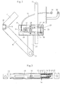
- an axial section through the connecting rod 42 is shown enlarged.
- the rod 44 has an elongated hole 45 through which a pin 46 seated in the tube 43 is inserted.
- the end of the rod 44 protruding into the tube 43 is tapered onto a cylindrical extension 48 via a conical shoulder 47.
- a split pin 49 at the end secures a washer 50.
- a package of is supported against this Disc springs 51 from.
- the plate spring 52 facing the shoulder 47 is conical opposite the shoulder 47 and presses a plurality of balls 53 against the shoulder 47 and the tube 43. These balls 53 act as a brake 54 against a displacement of the rod 44 in the tube 43, the braking effect being from the direction of displacement depends:
- the connecting rod 42 is pulled apart, the escaping shoulder 47 exerts a slight braking force on the balls 53 rolling on the tube 43, while these wedge more when the connecting rod 42 is pressed between the tube 43 and the shoulder 47 and brake strongly.
- the connecting rod is normally in the basic position shown in FIG. 3, in which the pin 46 rests on the end of the elongated hole 45 facing the shoulder 47, because the mattress frame 2 is slightly foot-heavy and therefore the connecting rod 42 is normally subjected to tension.
- a lifting motor 58 is articulated to the base frame 1. Its lifting rod 59 is articulated on the arm 40. Their stroke is limited in both directions by limit switches, not shown.
- the mattress frame 2 If the mattress frame 2 is then raised again with the motor 58, it first lifts off the stop 64 and the connecting rod 42 is pulled out again until the pin 46 stops at the end of the elongated hole 45, so that the mattress frame again assumes the previously set inclination.
- the braking force of the brake 54 is lower, so that a mere slight load on the feet of the mattress frame 2 is sufficient. If the head end is heavily loaded when the mattress frame 2 is raised, the connecting rod 42 telescopes only slowly because of the brake 54, so that there are no abrupt movements of the mattress frame which are unpleasant for the patient.
- the pivot axis 13 can be placed in the center of gravity of the occupied mattress frame 2 if in the connecting rod 42 an additional compression spring between the free end of the extension 48 and the free end of the tube 43 is excited. In this variant, however, the set inclination is lost when the handle 35 is actuated in the lower limit position of the mattress frame.
Landscapes
- Health & Medical Sciences (AREA)
- Nursing (AREA)
- Life Sciences & Earth Sciences (AREA)
- Animal Behavior & Ethology (AREA)
- General Health & Medical Sciences (AREA)
- Public Health (AREA)
- Veterinary Medicine (AREA)
- Rehabilitation Therapy (AREA)
- Invalid Beds And Related Equipment (AREA)
- Orthopedics, Nursing, And Contraception (AREA)
- External Artificial Organs (AREA)
Abstract
Description
- Ein Krankenbett gemäss Oberbegriff des Anspruchs 1 ist aus der CH-PS 656'065 bekannt. Ein Matratzenrahmen ist gegenüber einem horizontalen Untergestell durch einen Hubmotor in der Höhe verstellbar. Dazu ist der Matratzenrahmen kopf- und fussseitig am freien Ende der einen Arme von doppelarmigen Hebeln abgestützt. Die andern Arme der Hebel sind durch eine Zugstange miteinander verbunden. Der fusseitige Hebel ist durch den Hubmotor verschwenkbar. Der erste Arm des kopfseitigen Hebels ist eine Stange eines Gelenkvierecks. Er kann durch Unterstellen eines Arretierhebels blockiert werden, so dass beim Absenken mittels des Hubmotors nur das fusseitige Ende sinkt. Die Zugstange hat zur Ueberbrückung der Relativbewegung zwischen den beiden doppelarmigen Hebeln ein Langloch.
- Dieses Krankenbett hat sich bewährt. Allerdings ist die Neigungsverstellung nur in einer gegebenen Höhenlage möglich.
- Wenn der Matratzenrahmen auf eine andere Höhe verstellt werden muss, z.B. zum Einstieg des Patienten oder für Massagen, muss die Neigung anschliessend erneut eingestellt werden.
- Ein weiteres Krankenbett ist aus der CH-PS 373'142 bekannt. Hier ist allerdings statt des Hubmotors eine Kurbel vorgesehen. Die den Matratzenrahmen fusseitig mit dem doppelarmigen Hebel verbindende Stütze ist teleskopisch in mehreren Stufen verlängerbar, so dass das Fussende gegenüber dem Kopfende angehoben werden kann. Ein Neigen des Matratzenrahmens mit dem Fussende nach unten ist nicht vorgesehen.
- Eine stufenlose Verstellvorrichtung, welche in beiden Richtungen sperrt, ist aus der CH-PS 451'432 bekannt.
- Der vorliegenden Erfindung liegt die Aufgabe zugrunde, ein Krankenbett der eingangs genannten Art derart auszubilden, dass die Neigung in unterschiedlichen Höhenlagen verstellt werden kann. Diese Aufgabe wird durch die kennzeichnenden Merkmale des Anspruchs 1 gelöst.
- Bei der erfindungsgemässen Ausbildung ist die Schwenkachse, um welche der Matratzenrahmen verschwenkbar gelagert ist, in der Nähe des Schwerpunktes des mit einer durchschnittlichen Person besetzten Matratzenrahmens mit Matratze angeordnet. Dadurch kann die zum Verstellen der Neigung erforderliche Kraft gering gehalten werden. Es ist daher ohne weiteres eine Handverstellung möglich. Wegen dieser Lagerung in Schwerpunktnähe sperrt das Klemmorgan für die stufenlose Verstellung in beiden Bewegungsrichtungen. Durch die gegen die Kraft einer Bremse veränderbare Länge der Verbindungsstange wird ermöglicht, dass der Matratzenrahmen bei fusseitiger Neigung beim Absenken zunächst am Fussende auf den zugehörigen Anschlägen am Untergestell aufliegt und bei weiterer Betätigung des Hubmotors durch Teleskopieren der Verbindungsstange in die horizontale Lage abgesenkt wird, wo der Matratzenrahmen beidenends auf den Anschlägen aufliegt, z.B. für Massagen. Mit dem Hubmotor kann also der Matratzenrahmen auch bei Schrägstellung bis zur Motorabschaltung durch den zu diesem Zweck üblicherweise eingebauten Endschalter gefahren werden. Beim anschliessenden Anheben des Matratzenrahmens nimmt dieser automatisch wieder seine zuvor eingestellte Neigung ein. Weil die Längenverstellung der Verbindungsstange gebremst ist, treten auch bei Fehlbelastung des Matratzenrahmens keine plötzlichen Neigungsänderungen auf.
- Nachfolgend wird ein Ausführungsbeispiel der Erfindung anhand der Zeichnung erläutert. Darin zeigt:
- Fig. 1 einen schematischen Längsschnitt durch ein erfindungsgemässes Krankenbett,
- Fig. 2 einen Vertikalschnitt durch ein Verbindungsglied, und
- Fig. 3 einen Axialschnitt durch eine Verbindungsstange.
- Das in Fig. 1 im Längsschnitt dargestellte Krankenbett umfasst ein horizontales Untergestell 1 und einen höhenverstellbaren Matratzenrahmen 2. Das Untergestell 1 ist auf vier Lenkrollen 3 fahrbar. Am Untergestell 1 sind zwei Paare zweiarmiger Hebel 4, 5 schwenkbar gelagert. Der eine Arm 6 des ersten, kopfseitigen Hebels 4 bildet den einen Stab eines Gelenkvierecks 7. Zwei der Gelenkpunkte 8, 9 des Gelenkvierecks 7 sind auf dem Untergestell 1 schwenkbar, wobei der Gelenkpunkt 8 durch ein am Untergestell drehbar gelagertes torsionssteifes Rohr gebildet ist. Die die beiden andern Gelenkpunkte 10, 11 des Gelenkvierecks 7 verbindende Stange 12 ist nach oben über den Gelenkpunkt 11 verlängert und ist an seinem freien Ende um eine horizontale Schwenkachse 13 schwenkbar mit dem Matratzenrahmen 2 in dessen mittlerem Drittel verbunden. Die Schwenkachse 13 liegt benachbart dem Schwerpunkt des mit einer Matratze und einer durchschnittlichen Person beladenen Matratzenrahmens 2, jedoch leicht gegen das Kopfende hin verschoben. Das Gelenkviereck 7 ist so ausgelegt, dass sich beim Verschwenken des Hebels 4 die Schwenkachse 13 annähernd in einer Vertikalebene bewegt, dass sich also der Matratzenrahmen 2 bei der Vertikalbewegung nur unwesentlich gegenüber dem Untergestell 1 horizontal verschiebt.
- Der zweite doppelarmige Hebel 5 ist benachbart dem Fussende am Untergestell 1 ebenfalls auf einem drehbaren torsionssteifen Rohr 18 befestigt. Das freie Ende seines einen Armes 19 ist gelenkig mit einem Verbindungsglied 20 verbunden, dessen anderes Ende am Matratzenrahmen 2 angelenkt ist. Die Länge des Verbindungsgliedes 20 zwischen seinen beiden Gelenken 21, 22 ist durch ein stufenlos verstellbares, in beiden Richtungen sperrendes Klemmorgan 23 einstellbar. Das Klemmorgan 23 (Fig. 2) besteht aus zwei in einem Gehäuse 24 am oberen Ende eines Trägers 25 eingesetzten Klemmplatten 26. Eine Bohrung 27 dieser Klemmplatten 26 ist mit Spiel auf einer Stange 28 geführt. Diese Stange 28 trägt am oberen Ende ein als das Gelenk 22 wirkendes Verbindungsrohr. Die Klemmplatten 26 sind durch drei quer zur Längsrichtung der Stange 28 im Gehäuse 24 sitzende Stifte 29 in Längsrichtung der Stange 28 fixiert, indem sie zwischen je zwei dieser Stifte 29 mit geringem Spiel eingesteckt sind. Auf der einen Seite werden die Klemmplatten 26 durch eine Druckfeder 30 voneinander gespreizt. Auf der andern Seite ist im Gehäuse 24 eine Torsionsstange 31 drehbar gelagert. Diese greift mit einer Abflachung 32 lose zwischen die beiden Klemmplatten 26. An einem mit der Stange 31 verbundenen Hebel 33 greift ein Kabelzug 34 an. Dessen anderes Ende ist mit einem Handgriff 35 benachbart einer Greifstange 36 verbunden. Durch Ziehen des Handgriffs 35 verschwenkt dic Stange 31, so dass die beiden Klemmplatten 26 entgegen der Kraft der Feder 30 verschwenkt werden und ihre Klemmwirkung aufgehoben wird. Mit der Greifstange 36 lässt sich dann der Matratzenrahmen um die Achse 13 verschwenken. Da diese Achse 13 benachbart dem Schwerpunkt angeordnet ist, ist der Kraftaufwand zum Verschwenken gering.
- Die beiden zweiten Arme 40, 41 der doppelarmigen Hebel 4, 5 sind an ihrem freien Ende über eine teleskopierbare Verbindungsstange 42 miteinander verbunden. Diese besteht aus einem am freien Ende des Arms 41 angelenkten Rohr 43 und einem im Rohr 43 längsverschiebbaren, am freien Ende des Armes 40 angelenkten Stab 44. In Fig. 3 ist ein Axialschnitt durch die Verbindungsstange 42 vergrössert dargestellt. Der Stab 44 hat ein Langloch 45, durch das ein im Rohr 43 sitzender Stift 46 gesteckt ist. Ueber eine konische Schulter 47 ist das in das Rohr 43 ragende Ende des Stabes 44 auf einen zylindrischen Ansatz 48 verjüngt. Ein Splint 49 an dessen Ende sichert eine Unterlagsscheibe 50. Gegen diese stützt sich ein Paket von Tellerfedern 51 ab. Die der Schulter 47 zugewandte Tellerfeder 52 ist entgegengesetzt der Schulter 47 konisch und drückt mehrere Kugeln 53 gegen die Schulter 47 und das Rohr 43. Diese Kugeln 53 wirken als Bremse 54 gegen eine Verschiebung des Stabes 44 im Rohr 43, wobei die Bremswirkung von der Verschieberichtung abhängt: Beim Auseinanderziehen der Verbindungsstange 42 übt die entweichende Schulter 47 eine geringe Bremskraft auf die auf dem Rohr 43 abrollenden Kugeln 53 aus, während sich diese beim Zusammendrücken der Verbindungsstange 42 zwischen Rohr 43 und Schulter 47 mehr verkeilen und stark bremsen. Die Verbindungsstange ist normalerweise in der in Fig. 3 dargestellten Grundstellung, in welcher der Stift 46 an dem der Schulter 47 zugewandten Ende des Langlochs 45 anliegt, weil der Matratzenrahmen 2 leicht fusslastig ist und daher die Verbindungsstange 42 im Normalfall auf Zug belastet ist.
- Zum Anheben und Absenken des Matratzenrahmens 2 ist ein Hubmotor 58 gelenkig mit dem Untergestell 1 verbunden. Seine Hubstange 59 ist am Arm 40 angelenkt. Ihr Hub ist durch nicht dargestellte Grenzschalter in beiden Richtungen begrenzt.
- Wird der Matratzenrahmen 2 bei abgesenktem Fussende mittels des Motors 58 nach unten gefahren, so stösst eine benachbart dem Fussende am Matratzenrahmen 2 gelagerte Rolle 62 gegen einen Anschlag 63, bevor der Motor 58 durch den unteren Grenz schalter abgeschaltet wird. Der doppelarmige Hebel 5 wird dadurch arretiert. Beim weiteren Absenken mittels des Motors 58 wird nun die Verbindungsstange 42 gegen die Kraft der Bremse 54 teleskopisch zusammengeschoben, bis der untere Grenzschalter den Motor 58 abstellt. Dabei liegt der Matratzenrahmen 2 auch auf der kopfseitigen Hälfte auf Anschlägen 64 auf und ist horizontal. Wird anschliessend der Matratzenrahmen 2 mit dem Motor 58 wieder hochgefahren, so hebt er zunächst vom Anschlag 64 ab und die Verbindungsstange 42 wird wieder bis zum Anschlag des Stiftes 46 am Ende des Langlochs 45 ausgezogen, so dass der Matratzenrahmen die zuvor eingestellte Neigung wieder einnimmt. Beim Ausziehen des Stabes 44 ist die Bremskraft der Bremse 54 geringer, so dass eine bloss geringfügige Fusslastigkeit des Matratzenrahmens 2 ausreicht. Wird bei angehobenem Matratzenrahmen 2 dessen Kopfende stark belastet, so teleskopiert die Verbindungsstange 42 wegen der Bremse 54 nur langsam, so dass keine abrupten, für den Patienten unangenehmen Bewegungen des Matratzenrahmens erfolgen.
- Die Schwenkachse 13 kann in den Schwerpunkt des belegten Matratzenrahmens 2 gelegt werden, wenn in der Verbindungsstange 42 zusätzlich eine Druckfeder zwischen dem freien Ende des Ansatzes 48 und dem freien Ende des Rohres 43 ein gespannt wird. Bei dieser Variante geht allerdings die eingestellte Neigung verloren, wenn in der unteren Grenzlage des Matratzenrahmens der Handgriff 35 betätigt wird.
Claims (7)
Priority Applications (1)
| Application Number | Priority Date | Filing Date | Title |
|---|---|---|---|
| AT89810113T ATE77934T1 (de) | 1988-02-25 | 1989-02-13 | Krankenbett. |
Applications Claiming Priority (2)
| Application Number | Priority Date | Filing Date | Title |
|---|---|---|---|
| CH709/88A CH675680A5 (de) | 1988-02-25 | 1988-02-25 | |
| CH709/88 | 1988-02-25 |
Publications (3)
| Publication Number | Publication Date |
|---|---|
| EP0330611A2 true EP0330611A2 (de) | 1989-08-30 |
| EP0330611A3 EP0330611A3 (en) | 1990-02-21 |
| EP0330611B1 EP0330611B1 (de) | 1992-07-08 |
Family
ID=4193340
Family Applications (1)
| Application Number | Title | Priority Date | Filing Date |
|---|---|---|---|
| EP89810113A Expired - Lifetime EP0330611B1 (de) | 1988-02-25 | 1989-02-13 | Krankenbett |
Country Status (4)
| Country | Link |
|---|---|
| EP (1) | EP0330611B1 (de) |
| AT (1) | ATE77934T1 (de) |
| CH (1) | CH675680A5 (de) |
| DE (1) | DE58901785D1 (de) |
Cited By (2)
| Publication number | Priority date | Publication date | Assignee | Title |
|---|---|---|---|---|
| EP0442043A1 (de) * | 1990-02-10 | 1991-08-21 | L. & C. ARNOLD AG | Krankenbett |
| GB2285619A (en) * | 1994-01-15 | 1995-07-19 | Smiths Industries Plc | Lift platforms |
Family Cites Families (3)
| Publication number | Priority date | Publication date | Assignee | Title |
|---|---|---|---|---|
| GB1036327A (en) * | 1963-11-12 | 1966-07-20 | Greater London Council | Ambulance stretcher-bed and seat |
| JPS56143159A (en) * | 1980-04-05 | 1981-11-07 | Kimura Shindai Kogyo Kk | Drive apparatus for lifting floor part |
| DE3516092A1 (de) * | 1985-05-04 | 1986-11-06 | Wilh. Berg GmbH & Co KG, 5990 Altena | Krankenbett mit einer hoehenverstellbaren sowie neigbaren liegeflaeche |
-
1988
- 1988-02-25 CH CH709/88A patent/CH675680A5/de not_active IP Right Cessation
-
1989
- 1989-02-13 DE DE8989810113T patent/DE58901785D1/de not_active Expired - Fee Related
- 1989-02-13 AT AT89810113T patent/ATE77934T1/de not_active IP Right Cessation
- 1989-02-13 EP EP89810113A patent/EP0330611B1/de not_active Expired - Lifetime
Cited By (2)
| Publication number | Priority date | Publication date | Assignee | Title |
|---|---|---|---|---|
| EP0442043A1 (de) * | 1990-02-10 | 1991-08-21 | L. & C. ARNOLD AG | Krankenbett |
| GB2285619A (en) * | 1994-01-15 | 1995-07-19 | Smiths Industries Plc | Lift platforms |
Also Published As
| Publication number | Publication date |
|---|---|
| ATE77934T1 (de) | 1992-07-15 |
| EP0330611A3 (en) | 1990-02-21 |
| EP0330611B1 (de) | 1992-07-08 |
| DE58901785D1 (de) | 1992-08-13 |
| CH675680A5 (de) | 1990-10-31 |
Similar Documents
| Publication | Publication Date | Title |
|---|---|---|
| DE3615572C2 (de) | Krankenhausbett | |
| DE2618943A1 (de) | Lehnstuhl mit motorisch betriebener kipplehnen- und sitzhebemechanik | |
| DE3313843C2 (de) | Krankenbett | |
| DE2534452A1 (de) | Bett mit verstellbarer matratzenaufnahme | |
| DE1529675B1 (de) | Senkrecht einstellbarer Bett-Tisch | |
| DE1766522A1 (de) | Krankenbett | |
| DE19701591A1 (de) | Badelift für Senioren und Behinderte | |
| DE19604549A1 (de) | Kranken- oder Pflegebett | |
| DE4135224A1 (de) | Liegebett | |
| EP0330611B1 (de) | Krankenbett | |
| DE3611436A1 (de) | Liege fuer patienten | |
| DE1290297C2 (de) | Halterung fuer einen zahnaerztlichen schwebetisch | |
| DE2531112A1 (de) | Hoehenverstellbares bett | |
| EP0853936B1 (de) | Badelift für Senioren und Behinderte | |
| AT396745B (de) | Verstellbare gelenkuntermatratze für ein spital- oder pflegebett | |
| DE4442039A1 (de) | Vorrichtung zum Hochlagern der Beine | |
| DE2049282C3 (de) | Patientenstuhl | |
| EP0819416B1 (de) | Vorrichtung zum Absenken und Heben einer behinderten Person | |
| DE3639216A1 (de) | Von hand hoehenverstellbarer podestbock | |
| DE2656668C3 (de) | Hubvorrichtung für eine höhenverstellbare und/oder in beliebigen Zwischenstellungen neigbare Fläche, z.B. für einen Matratzenrahmen eines Krankenbettes, für eine Endoskopieliege, für einen Operationstisch, für eine Bahre, für einen Untersuchungsstuhl, o.dgl | |
| DE3322017C2 (de) | ||
| DD300506A5 (de) | Bett | |
| DE19901127C2 (de) | Kranken- oder Pflegebett | |
| DE9202605U1 (de) | Krankenbett | |
| DE1491274A1 (de) | Krankenbett |
Legal Events
| Date | Code | Title | Description |
|---|---|---|---|
| PUAI | Public reference made under article 153(3) epc to a published international application that has entered the european phase |
Free format text: ORIGINAL CODE: 0009012 |
|
| AK | Designated contracting states |
Kind code of ref document: A2 Designated state(s): AT BE CH DE ES FR GB IT LI NL SE |
|
| PUAL | Search report despatched |
Free format text: ORIGINAL CODE: 0009013 |
|
| AK | Designated contracting states |
Kind code of ref document: A3 Designated state(s): AT BE CH DE ES FR GB IT LI NL SE |
|
| 17P | Request for examination filed |
Effective date: 19900315 |
|
| GRAA | (expected) grant |
Free format text: ORIGINAL CODE: 0009210 |
|
| AK | Designated contracting states |
Kind code of ref document: B1 Designated state(s): AT BE CH DE ES FR GB IT LI NL SE |
|
| PG25 | Lapsed in a contracting state [announced via postgrant information from national office to epo] |
Ref country code: IT Free format text: LAPSE BECAUSE OF FAILURE TO SUBMIT A TRANSLATION OF THE DESCRIPTION OR TO PAY THE FEE WITHIN THE PRE;WARNING: LAPSES OF ITALIAN PATENTS WITH EFFECTIVE DATE BEFORE 2007 MAY HAVE OCCURRED AT ANY TIME BEFORE 2007. THE CORRECT EFFECTIVE DATE MAY BE DIFFERENT FROM THE ONE RECORDED.SCRIBED TIME-LIMIT Effective date: 19920708 Ref country code: BE Effective date: 19920708 Ref country code: SE Effective date: 19920708 Ref country code: ES Free format text: THE PATENT HAS BEEN ANNULLED BY A DECISION OF A NATIONAL AUTHORITY Effective date: 19920708 Ref country code: GB Effective date: 19920708 |
|
| REF | Corresponds to: |
Ref document number: 77934 Country of ref document: AT Date of ref document: 19920715 Kind code of ref document: T |
|
| REF | Corresponds to: |
Ref document number: 58901785 Country of ref document: DE Date of ref document: 19920813 |
|
| EN | Fr: translation not filed | ||
| PG25 | Lapsed in a contracting state [announced via postgrant information from national office to epo] |
Ref country code: FR Effective date: 19921127 |
|
| GBV | Gb: ep patent (uk) treated as always having been void in accordance with gb section 77(7)/1977 [no translation filed] |
Effective date: 19920708 |
|
| PLBE | No opposition filed within time limit |
Free format text: ORIGINAL CODE: 0009261 |
|
| 26N | No opposition filed | ||
| REG | Reference to a national code |
Ref country code: FR Ref legal event code: ST |
|
| PGFP | Annual fee paid to national office [announced via postgrant information from national office to epo] |
Ref country code: NL Payment date: 19950228 Year of fee payment: 7 |
|
| PG25 | Lapsed in a contracting state [announced via postgrant information from national office to epo] |
Ref country code: NL Effective date: 19960901 |
|
| NLV4 | Nl: lapsed or anulled due to non-payment of the annual fee |
Effective date: 19960901 |
|
| PGFP | Annual fee paid to national office [announced via postgrant information from national office to epo] |
Ref country code: CH Payment date: 19970109 Year of fee payment: 9 |
|
| REG | Reference to a national code |
Ref country code: CH Ref legal event code: NV Representative=s name: PATENTANWALTS-BUREAU ISLER AG |
|
| PGFP | Annual fee paid to national office [announced via postgrant information from national office to epo] |
Ref country code: AT Payment date: 19980115 Year of fee payment: 10 |
|
| PGFP | Annual fee paid to national office [announced via postgrant information from national office to epo] |
Ref country code: DE Payment date: 19980126 Year of fee payment: 10 |
|
| PG25 | Lapsed in a contracting state [announced via postgrant information from national office to epo] |
Ref country code: CH Free format text: LAPSE BECAUSE OF NON-PAYMENT OF DUE FEES Effective date: 19980228 Ref country code: LI Free format text: LAPSE BECAUSE OF NON-PAYMENT OF DUE FEES Effective date: 19980228 |
|
| REG | Reference to a national code |
Ref country code: CH Ref legal event code: PL |
|
| PG25 | Lapsed in a contracting state [announced via postgrant information from national office to epo] |
Ref country code: AT Free format text: LAPSE BECAUSE OF NON-PAYMENT OF DUE FEES Effective date: 19990213 |
|
| PG25 | Lapsed in a contracting state [announced via postgrant information from national office to epo] |
Ref country code: DE Free format text: LAPSE BECAUSE OF NON-PAYMENT OF DUE FEES Effective date: 19991201 |