EP0330705A1 - Verfahren und Vorrichtung zur Behandlung von Gegenständen mit Elektronenstrahlung und/oder elektromagnetischer Strahlung unter Schutzgas - Google Patents
Verfahren und Vorrichtung zur Behandlung von Gegenständen mit Elektronenstrahlung und/oder elektromagnetischer Strahlung unter Schutzgas Download PDFInfo
- Publication number
- EP0330705A1 EP0330705A1 EP88102981A EP88102981A EP0330705A1 EP 0330705 A1 EP0330705 A1 EP 0330705A1 EP 88102981 A EP88102981 A EP 88102981A EP 88102981 A EP88102981 A EP 88102981A EP 0330705 A1 EP0330705 A1 EP 0330705A1
- Authority
- EP
- European Patent Office
- Prior art keywords
- protective gas
- gas
- zone
- radiation
- additional amount
- Prior art date
- Legal status (The legal status is an assumption and is not a legal conclusion. Google has not performed a legal analysis and makes no representation as to the accuracy of the status listed.)
- Granted
Links
- 238000000034 method Methods 0.000 title claims abstract description 18
- 239000011261 inert gas Substances 0.000 title abstract description 9
- 239000007789 gas Substances 0.000 claims description 68
- 230000001681 protective effect Effects 0.000 claims description 44
- 230000005855 radiation Effects 0.000 claims description 29
- 230000001960 triggered effect Effects 0.000 claims description 11
- IJGRMHOSHXDMSA-UHFFFAOYSA-N Atomic nitrogen Chemical compound N#N IJGRMHOSHXDMSA-UHFFFAOYSA-N 0.000 claims description 6
- 229910052751 metal Inorganic materials 0.000 claims description 4
- 239000002184 metal Substances 0.000 claims description 4
- 229910052757 nitrogen Inorganic materials 0.000 claims description 3
- 230000005670 electromagnetic radiation Effects 0.000 claims description 2
- QVGXLLKOCUKJST-UHFFFAOYSA-N atomic oxygen Chemical compound [O] QVGXLLKOCUKJST-UHFFFAOYSA-N 0.000 description 8
- 239000001301 oxygen Substances 0.000 description 8
- 229910052760 oxygen Inorganic materials 0.000 description 8
- 230000002349 favourable effect Effects 0.000 description 3
- 238000003860 storage Methods 0.000 description 3
- XKRFYHLGVUSROY-UHFFFAOYSA-N Argon Chemical compound [Ar] XKRFYHLGVUSROY-UHFFFAOYSA-N 0.000 description 2
- ATUOYWHBWRKTHZ-UHFFFAOYSA-N Propane Chemical compound CCC ATUOYWHBWRKTHZ-UHFFFAOYSA-N 0.000 description 2
- 238000013459 approach Methods 0.000 description 2
- 238000009826 distribution Methods 0.000 description 2
- VNWKTOKETHGBQD-UHFFFAOYSA-N methane Chemical compound C VNWKTOKETHGBQD-UHFFFAOYSA-N 0.000 description 2
- 238000011144 upstream manufacturing Methods 0.000 description 2
- UGFAIRIUMAVXCW-UHFFFAOYSA-N Carbon monoxide Chemical compound [O+]#[C-] UGFAIRIUMAVXCW-UHFFFAOYSA-N 0.000 description 1
- 238000005299 abrasion Methods 0.000 description 1
- 229910052786 argon Inorganic materials 0.000 description 1
- 230000015572 biosynthetic process Effects 0.000 description 1
- 229910002091 carbon monoxide Inorganic materials 0.000 description 1
- 238000003776 cleavage reaction Methods 0.000 description 1
- 238000005260 corrosion Methods 0.000 description 1
- 230000007797 corrosion Effects 0.000 description 1
- 238000004132 cross linking Methods 0.000 description 1
- 238000010894 electron beam technology Methods 0.000 description 1
- 230000005284 excitation Effects 0.000 description 1
- 230000009931 harmful effect Effects 0.000 description 1
- 238000009434 installation Methods 0.000 description 1
- 230000001678 irradiating effect Effects 0.000 description 1
- 238000004519 manufacturing process Methods 0.000 description 1
- 239000000463 material Substances 0.000 description 1
- 238000012544 monitoring process Methods 0.000 description 1
- 239000003345 natural gas Substances 0.000 description 1
- 239000003973 paint Substances 0.000 description 1
- 230000035515 penetration Effects 0.000 description 1
- 229920003023 plastic Polymers 0.000 description 1
- 239000004033 plastic Substances 0.000 description 1
- 238000006116 polymerization reaction Methods 0.000 description 1
- 239000001294 propane Substances 0.000 description 1
- 230000007017 scission Effects 0.000 description 1
- 238000009827 uniform distribution Methods 0.000 description 1
Images
Classifications
-
- B—PERFORMING OPERATIONS; TRANSPORTING
- B01—PHYSICAL OR CHEMICAL PROCESSES OR APPARATUS IN GENERAL
- B01J—CHEMICAL OR PHYSICAL PROCESSES, e.g. CATALYSIS OR COLLOID CHEMISTRY; THEIR RELEVANT APPARATUS
- B01J19/00—Chemical, physical or physico-chemical processes in general; Their relevant apparatus
- B01J19/08—Processes employing the direct application of electric or wave energy, or particle radiation; Apparatus therefor
-
- B—PERFORMING OPERATIONS; TRANSPORTING
- B01—PHYSICAL OR CHEMICAL PROCESSES OR APPARATUS IN GENERAL
- B01J—CHEMICAL OR PHYSICAL PROCESSES, e.g. CATALYSIS OR COLLOID CHEMISTRY; THEIR RELEVANT APPARATUS
- B01J19/00—Chemical, physical or physico-chemical processes in general; Their relevant apparatus
- B01J19/14—Production of inert gas mixtures; Use of inert gases in general
-
- B—PERFORMING OPERATIONS; TRANSPORTING
- B29—WORKING OF PLASTICS; WORKING OF SUBSTANCES IN A PLASTIC STATE IN GENERAL
- B29C—SHAPING OR JOINING OF PLASTICS; SHAPING OF MATERIAL IN A PLASTIC STATE, NOT OTHERWISE PROVIDED FOR; AFTER-TREATMENT OF THE SHAPED PRODUCTS, e.g. REPAIRING
- B29C71/00—After-treatment of articles without altering their shape; Apparatus therefor
- B29C71/04—After-treatment of articles without altering their shape; Apparatus therefor by wave energy or particle radiation, e.g. for curing or vulcanising preformed articles
Definitions
- the invention relates to a method and a device for treating objects with electron radiation and / or electromagnetic radiation under protective gas in a continuous device with an entrance, exit and radiation zone.
- Plastics can be changed by the influence of high-energy radiation in the molecular structure. There are, for example, the following possibilities: excitation of a polymerization by radiation, cleavage of chain molecules, formation of side chains, cross-linking of chains, etc. Material properties can be changed by such processes, in the case of paints, for example, the corrosion resistance and abrasion resistance. Radiation treatment must be carried out in a protective gas atmosphere in the region of the radiation zone in order to avoid harmful effects, for example of oxygen.
- the object of the present invention is therefore to provide a method which is both reliable and economical for producing a protective gas atmosphere.
- This object is achieved in that an additional amount of protective gas is supplied to a constant base amount of protective gas in phases depending on the passage of the objects to be irradiated through the passage device.
- the protective gas supply according to the invention minimizes the need for protective gas. Compared to a constant addition of protective gas, the amount of gas required can be significantly reduced. In the case of a gas supply from storage tanks, there is a considerable increase in operational safety with regard to the protective gas unit in comparison to the protective gas supply with a gas generator.
- the invention is based on the finding that air is introduced into the objects which pass through the installation, which causes an increase in the oxygen content. Therefore, the addition of additional amounts of protective gas at certain times during the passage of the objects is advantageous and sufficient to maintain the necessary purity of the protective gas atmosphere.
- a phase of adding the additional amount of protective gas is carried out before the objects to be irradiated enter and / or exit the irradiation zone.
- the duration of an addition phase depends on several parameters. The most important of these are: length and tightness of the entrance and exit zone, the throughput speed, shape and dimensions of the object to be treated. Favorable conditions exist for a period of around 5 to 40% of the throughput time of an object through the system.
- the base amount and the additional amount are added in a ratio of 1: 1 to 1: 0.3. This ensures both the cost-effectiveness of the process and the purity of the protective gas.
- the supply of the additional amount of protective gas is triggered by signal transmitters which are triggered by the objects to be irradiated as they pass through the device.
- the addition of protective gas can be triggered several times by a signal generator, e.g. on arrival and on leaving the signal transmitter.
- Nitrogen which is comparatively inexpensive to obtain in storage containers, is particularly suitable as a protective gas.
- inert gases e.g. Argon
- Argon can be used.
- a continuous device suitable for carrying out the method with an input, an output and an irradiation zone is characterized in that signal transmitters for triggering the addition of the additional amount of protective gas are arranged in the input zone and / or the output zone.
- the protective gas addition is controlled with these signal transmitters and the process sequence according to the invention is thus automated.
- the arrangement of a gas distributor directly adjacent to the radiation zone or a gas distributor immediately before and a gas distributor directly after the radiation region, through which the protective gas is introduced into the flow-through device, is particularly favorable.
- a gas distributor has proven to be particularly suitable, which consists of a housing which is closed at the bottom by a gas-permeable sintered metal plate, a distributor tube being arranged in the housing in an upwardly open U-shaped distributor channel, and the distributor channel at the top and to the side is arranged at a distance from the housing.
- the distributor pipe has downward openings through which the gas is introduced into the housing, which then flows upwards through the distributor channel until it finally emerges from the distributor again through the sintered metal plate due to the lateral distance of the channel from the housing.
- the arrangement of closure elements in the outlet zone of the flow device is advantageous.
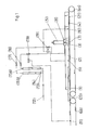
- FIG. 1 shows a continuous device according to the invention for irradiating objects with electron radiation with a continuous channel 1 consisting of entrance zone 2, irradiation zone 3 and exit zone 4
- the radiation device 5 is arranged above the radiation zone 3 in the middle of the flow channel 1.
- the objects 20 to be irradiated are conveyed through the continuous device by means of a conveyor system 6a, for example a conveyor belt.
- the protective gas is introduced via two gas distributors 8 arranged directly next to the electron beam channel 7.
- a signal transmitter 9, for example a photocell, is arranged in the input zone 2 of the continuous device at a distance from the radiation zone 3.
- Another signal generator 10 is provided in the exit zone of the flow device and a third signal generator 11 is already arranged before entry into the flow channel.
- a protective gas is supplied to the gas distributors 8 via a protective gas supply line 12, which is divided into a basic quantity supply line 13 and an additional quantity supply line 14 with flow meters 15a, 15b and adjusting valves 16, 17.
- the basic quantity supply line 13 and the additional quantity supply line 14 are each opened and closed by solenoid valves 18, 19, the solenoid valves 18, 19 being controlled by their associated signal transmitters 11, 9 or 10.
- solenoid valves 18, 19 being controlled by their associated signal transmitters 11, 9 or 10.
- An object 20 to be irradiated is brought up by means of a conveyor system 6b, the supply of the base gas quantity of protective gas being triggered by the solenoid valve 18 by the signal transmitter 11 upstream of the flow device. Nitrogen is used as the protective gas.
- the additional amount of protective gas is triggered when the signal transmitter 9 is passed in the input zone 2.
- the signal transmitter 9 is arranged so far in front of the radiation zone that the air brought in by the object 20 - the object acts in the flow channel 1 like a piston - does not penetrate into the radiation zone 3.
- the addition of additional protective gas thus triggered serves to ensure that the oxygen content in the radiation zone does not increase significantly during the approach of an object.
- a second addition phase of the additional quantity is triggered.
- This also serves to limit the penetration of oxygen from the suction of the object passing through into the radiation area.
- the two phases of addition may coincide.
- Example values are: Length of the pass device: 4 m Entrance Zone Length: 2.5 m Distance of the upstream photocell from the radiation zone: 3.5 m Distance of the photocell in the entrance zone from the radiation zone: 0.5 m Tunnel height: 0.06 m Base quantity: 40 Nm3 / h Additional quantity: 20 Nm3 / h Lead time: 10 sec. Duration of the additional allowance: 2 sec.
- Oxygen content in the radiation zone ⁇ 60 ppm Constant addition quantity in order to obtain a protective atmosphere of approximately the same purity: approx. 60 Nm3 / h.
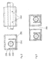
- FIG. 2 shows a gas distributor which has proven to be particularly suitable for carrying out the method.
- a U-shaped distributor channel 32 is arranged in an approximately square housing 31, in which a distributor pipe 33 with bores 34 is attached.
- the distribution channel is open at the top and connected to the housing wall on one leg.
- This distributor is characterized by an optimally uniform distribution of the protective gas supplied.
- FIG. 3 finally shows a particularly favorable double arrangement of two gas distributors just described, the radiation being able to enter the flow channel through the space 35 provided between the two.
Landscapes
- Chemical & Material Sciences (AREA)
- Organic Chemistry (AREA)
- Chemical Kinetics & Catalysis (AREA)
- Health & Medical Sciences (AREA)
- General Health & Medical Sciences (AREA)
- Toxicology (AREA)
- Physical Or Chemical Processes And Apparatus (AREA)
- Furnace Details (AREA)
Abstract
Description
- Die Erfindung betrifft ein Verfahren und eine Vorrichtung zur Behandlung von Gegenständen mit Elektronenstrahlung und/oder elektromagnetischer Strahlung unter Schutzgas in einer Durchlaufvorrichtung mit Eingangs-, Ausgangs- und Bestrahlungszone.
- Kunststoffe können durch den Einfluß energiereicher Strahlung im Molekülaufbau verändert werden. Es bestehen z.B. folgende Möglichkeiten: Anregung einer Polymerisation durch Strahlung, Spaltung von Kettenmolekülen, Bildung von Seitenketten, Quervernetzung von Ketten etc.. Durch solche Vorgänge können Materialeigenschaften verändert werden, bei Lacken z.B. die Korrosionsbeständigkeit und Abriebfestigkeit. Eine Strahlungsbehandlung muß zur Vermeidung von schädlichen Einflüssen z.B. von Sauerstoff, in einer Schutzgasatmosphäre im Bereich der Bestrahlungszone durchgeführt werden.
- Es ist bekannt, mit Hilfe eines Gasgenerators durch Verbrennung von z.B. Erdgas oder Propan ein Schutzgas herzustellen und damit den Luftsauerstoff aus dem Bestrahlungsbereich einer Bestrahlungsanlage durch ständiges Einführen von Schutzgas in die Anlage zu verdrängen. Dabei besteht aber die Bedingung, daß das Schutzgas selbst nur einen geringen Anteil an Sauerstoff und auch Kohlenmonoxid enthalten darf. Nur mit einwandfrei arbeitenden Gasgeneratoren ist diese Bedingung einzuhalten. Zur Kontrolle und um größere Mengen Ausschuß zu vermeiden, ist aber eine Überwachung des Schutzgases mit Detektoren unumgänglich. Das Betreiben einer derartigen Bestrahlungsvorrichtung setzt also die Anschaffung und den sorgfältigen Betrieb einer Gasgeneratoranlage voraus.
- Als Alternative zur Schutzgasherstellung mit einem Gasgenerator wäre eine Schutzgasversorgung mit aus Behältern entnehmbarem Schutzgas denkbar. Diese Möglichkeit ist jedoch bei direktem Ersatz von Generatorgas durch Speichergas wegen der benötigten großen Menge aus Kostengründen nicht sinnvoll.
- Die Aufgabenstellung der vorliegenden Erfindung besteht deshalb darin, ein sowohl zuverlässiges wie auch wirtschaftliches Verfahren zur Herstellung einer Schutzgasatmosphäre anzugeben.
- Diese Aufgabe wird dadurch gelöst, daß zu einer konstanten Basismenge an Schutzgas phasenweise in Abhängigkeit vom Durchlauf der zu bestrahlenden Gegenstände durch die Durchlaufvorrichtung, eine Zusatzmenge an Schutzgas zugeführt wird.
- Durch die erfindungsgemäße Schutzgaszufuhr wird der Bedarf an Schutzgas minimiert. Im Vergleich zu einer konstanten Schutzgaszugabe kann die benötigte Gasmenge wesentlich gesenkt werden. Bei einer Gasversorgung aus Speicherbehältern kommt dazu eine erhebliche Erhöhung der Betriebssicherheit bezüglich der Schutzgaseinheit im Vergleich zur Schutzgasversorgung mit Gasgenerator. Der Erfindung liegt die Erkenntnis zugrunde, daß durch die Gegenstände, die die Anlage durchlaufen, Luft in dieselbe eingeführt wird, die einen Anstieg des Sauerstoffgehalts bewirkt. Deshalb ist die Zugabe von zusätzlichen Mengen Schutzgas zu bestimmten Zeitpunkten des Durchlaufs der Gegenstände vorteilhaft und ausreichend, die notwendige Reinheit der Schutzgasatmosphäre zu erhalten.
- In einer vorteilhaften Ausgestaltung wird eine Phase der Zugabe der Zusatzmenge an Schutzgas vor dem Einlaufen und/oder vor dem Auslaufen der zu bestrahlenden Gegenstände in die bzw. aus der Bestrahlungszone durchgeführt.
- Dies führt dazu, daß bei langen Gegenständen zwei Zugabephasen während des Durchlaufs ausgelöst werden. Bei kurzen Gegenständen ergibt sich nur eine Zugabephase.
- Die Dauer einer Zugabephase ist von mehreren Parametern abhängig. Die wichtigsten davon sind: Länge und Dichtigkeit der Eingangs- und Ausgangszone, die Durchlaufgeschwindigkeit, Form und Abmessungen des zu behandelnden Gegenstandes. Günstige Bedingungen bestehen bei einer Zeitdauer von etwa 5 bis 40 % der Durchlaufzeit eines Gegenstandes durch die Anlage.
- Vorteilhaft ist es, wenn Basismenge und Zusatzmenge in einem Verhältnis von 1 : 1 bis 1 : 0,3 zugeführt werden. Damit ist sowohl die Wirtschaftlichkeit des Verfahrens als auch die Schutzgasreinheit sichergestellt.
- In einer besonders vorteilhaften Ausgestaltung des erfindungsgemäßen Verfahrens wird die Zufuhr der Zusatzmenge Schutzgas durch Signalgeber ausgelöst, die von den zu bestrahlenden Gegenständen bei ihrem Durchlauf durch die Vorrichtung ausgelöst werden. In bestimmten Fällen kann die Zufuhr der Zusatzmenge Schutzgas mehrmals durch einen Signalgeber ausgelöst werden, z.B. beim Eintreffen am und beim Verlassen des Signalgebers.
- Besonders geeignet als Schutzgas ist Stickstoff, der vergleichsweise kostengünstig in Speicherbehältern erhältlich ist. Es sind aber auch andere Inertgas, z.B. Argon, einsetzbar.
- Eine zur Durchführung des Verfahrens geeignete Durchlaufvorrichtung mit einer Eingangs-, einer Ausgangs- und einer Bestrahlungszone ist dadurch gekennzeichnet, daß in der Eingangszone und/oder der Ausgangszone Signalgeber zur Auslösung der Zugabe der Zusatzmenge an Schutzgas angeordnet sind. Mit diesen Signalgebern wird die Schutzgaszugabe gesteuert und so der erfindungsgemäße Verfahrensablauf automatisiert.
- Besonders günstig ist die Anordnung eines Gasverteilers direkt benachbart zur Bestrahlungszone oder eines Gasverteilers unmittelbar vor und eines Gasverteilers unmittelbar nach dem Bestrahlungsbereich, durch die das Schutzgas in die Durchlaufvorrichtung eingeleitet wird.
- Als besonders geeignet hat sich ein Gasverteiler erwiesen, der aus einem Gehäuse besteht, das nach unten durch eine gasdurchlässige Sintermetallplatte abgeschlossen ist, wobei in dem Gehäuse ein Verteilerrohr in einem nach oben geöffneten U-förmigen Verteilerkanal angeordnet ist, und der Verteilerkanal nach oben und seitlich mit Abstand zum Gehäuse angeordnet ist. Das Verteilerrohr besitzt nach unten gerichtete Öffnungen, durch die das Gas in das Gehäuse eingeleitet wird, welches dann durch den Verteilerkanal geführt nach oben fließt, bis es schließlich durch den seitlichen Abstand des Kanals vom Gehäuse nach unten durch die Sintermetallplatte wieder aus dem Verteiler austritt.
- Zum Schutz gegen das Eindringen von Sauerstoff von der Ausgangsseite ist die Anordnung von Abschließelementen in der Ausgangszone der Durchlaufvorrichtung vorteilhaft.
- Anhand der folgenden Zeichnungen soll die Erfindung beispielhaft erläutert werden.
- Es zeigen:
- Figur 1 erfindungsgemäße Durchlaufbestrahlungsanlage mit externer Gasversorgung,
- Figur 2 Gasverteiler in Vorder- und Seitensicht,
- Figur 3 Doppelanordnung von Gasverteilern.
- Figur 1 zeigt eine erfindungsgemäße Durchlaufvorrichtung zur Bestrahlung von Gegenständen mit Elektronenstrahlung mit einem Durchlaufkanal 1 bestehend aus Eingangszone 2, Bestrahlungszone 3 und Ausgangszone 4. Etwa in der Mitte des Durchlaufkanals 1 ist das Bestrahlungsgerät 5 über der Bestrahlungszone 3 angeordnet. Die zu bestrahlenden Gegenstände 20 werden mit einer Förderanlage 6a, z.B. einem Förderband, durch die Durchlaufvorrichtung befördert. Die Einleitung des Schutzgases erfolgt über zwei unmittelbar neben dem Elektronenstrahlkanal 7 angeordnete Gasverteiler 8. Ein Signalgeber 9, z.B. eine Photozelle, ist in der Eingangszone 2 der Durchlaufvorrichtung mit Abstand zur Bestrahlungszone 3 angeordnet. Ein weiterer Signalgeber 10 ist in der Ausgangszone der Durchlaufvorrichtung vorgesehen und ein dritter Signalgeber 11 ist bereits vor dem Zutritt in den Durchlaufkanal angeordnet. Über eine Schutzgaszuleitung 12, die sich in eine Basismengenzuleitung 13 und eine Zusatzmengenzuleitung 14 mit Mengenmessern 15a, 15b und Einstellventilen 16, 17 aufteilt, wird den Gasverteilern 8 Schutzgas zugeführt. Dabei wird die Basismengenzuleitung 13 und die Zusatzmengenzuleitung 14 jeweils durch Magnetventile 18, 19 geöffnet und geschlossen, wobei die Magnetventile 18, 19 von ihren zugehörigen Signalgebern 11, 9 oder 10 angesteuert werden. Prinzipiell ist anzumerken, daß es besonders vorteilhaft ist, wenn das Volumen des Durchlaufkanals möglichst klein gehalten wird, weil man dadurch einen besonders niedrigen Schutzgasbedarf erreicht. Dies kommt in der in Figur 1 dargestellten Anlage dadurch zum Ausdruck, daß die Förderanlage 6a nicht vollständig vom Vorrichtungsgehäuse 21 umfaßt wird.
- Ein zu bestrahlender Gegenstand 20 wird mittels einer Förderanlage 6b herangeführt, wobei durch den der Durchlaufvorrichtung vorgelagerten Signalgeber 11 die Zuführung der Basisgasmenge an Schutzgas durch das Magnetventil 18 ausgelöst wird. Als Schutzgas wird Stickstoff verwendet. Nach Eintreten des Gegenstandes in die Durchlaufvorrichtung wird beim Passieren des Signalgebers 9 in der Eingangszone 2 die Zusatzmenge an Schutzgas ausgelöst. Der Signalgeber 9 ist dabei soweit vor der Bestrahlungszone angeordnet, daß die durch den Gegenstand 20 mit herangeführte Luft - der Gegenstand wirkt im Durchlaufkanal 1 ähnlich wie ein Kolben - nicht in die Bestrahlungszone 3 eindringt. Die so ausgelöste Zugabe an zusätzlichem Schutzgas dient also dazu, daß der Sauerstoffgehalt in der Bestrahlungszone während der Annäherung eines Gegenstandes nicht wesentlich steigt. Ebenso wird,wenn sich das Ende des durchlaufenden Gegenstandes dem Bestrahlungsbereichs nähert durch den Signalgeber 10 oder ein zweites Mal durch Signalgeber 9, letzteres insbesondere wenn es sich um lange Gegenstände handelt, eine zweite Zugabephase der Zusatzmenge ausgelöst. Dies dient ebenfalls dazu, das Eindringen von Sauerstoff aus dem Sog des durchlaufenden Gegenstandes in den Bestrahlungsbereich zu beschränken. Bei kurzen Gegenständen fallen die beiden Zugabephasen unter Umständen zusammen.
Beispielswerte sind: Länge der Durchlaufvorrichtung: 4 m Länge der Eingangszone: 2,5 m Abstand der vorgelagerten Fotozelle von der Bestrahlungszone: 3,5 m Abstand der Fotozelle in der Eingangszone von der Bestrahlungszone: 0,5 m Tunnelhöhe: 0,06 m Basismenge: 40 Nm³/h Zusatzmenge: 20 Nm³/h Durchlaufzeit: 10 sec. Dauer der Zusatzzugabe: 2 sec. Sauerstoffgehalt in der Bestrahlungszone: ≦ 60 ppm Konstante Zugabemenge um Schutzatmosphäre etwa gleicher Reinheit zu bekommen: ca. 60 Nm³/h. - Figur 2 zeigt einen Gasverteiler, der sich als besonders geeignet zur Durchführung des Verfahrens erwiesen hat. In einem etwa quadratischen Gehäuse 31 ist ein U-förmiges Verteilerkanal 32 angeordnet, in dem ein Verteilerrohr 33 mit Bohrungen 34 angebracht ist. Der Verteilerkanal ist nach oben geöffnet und an einem Schenkel mit der Gehäusewand verbunden. Auf der der Befestigungswand abgewandten Seite des Verteilerkanals besteht ein Abstand zum Gehäuse, durch den das eingeleitete Schutzgas nach unten durch die gasdurchlässige Sintermetallplatte 35 aus dem Gehäuse ausfließt. Dieser Verteiler zeichnet sich durch optimal gleichmäßige Verteilung des zugeführten Schutzgases aus.
- Figur 3 zeigt schließlich eine besonders günstige Doppelanordnung von zwei eben beschriebenen Gasverteilern, wobei durch den zwischen beiden vorgesehenen Zwischenraum 35 die Strahlung in den Durchlaufkanal einfallen kann.
Claims (12)
Priority Applications (4)
| Application Number | Priority Date | Filing Date | Title |
|---|---|---|---|
| EP88102981A EP0330705B1 (de) | 1988-02-29 | 1988-02-29 | Verfahren und Vorrichtung zur Behandlung von Gegenständen mit Elektronenstrahlung und/oder elektromagnetischer Strahlung unter Schutzgas |
| ES198888102981T ES2030778T3 (es) | 1988-02-29 | 1988-02-29 | Procedimiento y dispositivo para tratar objetos con radiacion de electrones y/o radiacion electromagnetica bajo gas protector. |
| AT88102981T ATE73387T1 (de) | 1988-02-29 | 1988-02-29 | Verfahren und vorrichtung zur behandlung von gegenstaenden mit elektronenstrahlung und/oder elektromagnetischer strahlung unter schutzgas. |
| DE8888102981T DE3869121D1 (de) | 1988-02-29 | 1988-02-29 | Verfahren und vorrichtung zur behandlung von gegenstaenden mit elektronenstrahlung und/oder elektromagnetischer strahlung unter schutzgas. |
Applications Claiming Priority (1)
| Application Number | Priority Date | Filing Date | Title |
|---|---|---|---|
| EP88102981A EP0330705B1 (de) | 1988-02-29 | 1988-02-29 | Verfahren und Vorrichtung zur Behandlung von Gegenständen mit Elektronenstrahlung und/oder elektromagnetischer Strahlung unter Schutzgas |
Publications (2)
| Publication Number | Publication Date |
|---|---|
| EP0330705A1 true EP0330705A1 (de) | 1989-09-06 |
| EP0330705B1 EP0330705B1 (de) | 1992-03-11 |
Family
ID=8198760
Family Applications (1)
| Application Number | Title | Priority Date | Filing Date |
|---|---|---|---|
| EP88102981A Expired - Lifetime EP0330705B1 (de) | 1988-02-29 | 1988-02-29 | Verfahren und Vorrichtung zur Behandlung von Gegenständen mit Elektronenstrahlung und/oder elektromagnetischer Strahlung unter Schutzgas |
Country Status (4)
| Country | Link |
|---|---|
| EP (1) | EP0330705B1 (de) |
| AT (1) | ATE73387T1 (de) |
| DE (1) | DE3869121D1 (de) |
| ES (1) | ES2030778T3 (de) |
Cited By (3)
| Publication number | Priority date | Publication date | Assignee | Title |
|---|---|---|---|---|
| EP0490854A3 (en) * | 1990-12-07 | 1992-09-16 | Institutet Polymerutveckling Ab | Process and equipment for continuous crosslinking of polymeric materials and useful photo-initiators for the reaction |
| WO2001014483A1 (de) * | 1999-08-25 | 2001-03-01 | Basf Aktiengesellschaft | Verfahren zur herstellung kratzfester beschichtungen |
| US6727508B1 (en) | 1999-10-12 | 2004-04-27 | Toyo Ink Manufacturing Co., Ltd. | Method and apparatus for irradiating active energy ray |
Citations (2)
| Publication number | Priority date | Publication date | Assignee | Title |
|---|---|---|---|---|
| FR2157915A1 (en) * | 1971-10-26 | 1973-06-08 | Werner & Pfleiderer | Radiation curing - coated boards transported continuously through radiation zone |
| US4118873A (en) * | 1976-12-13 | 1978-10-10 | Airco, Inc. | Method and apparatus for inerting the atmosphere above a moving product surface |
-
1988
- 1988-02-29 DE DE8888102981T patent/DE3869121D1/de not_active Expired - Fee Related
- 1988-02-29 EP EP88102981A patent/EP0330705B1/de not_active Expired - Lifetime
- 1988-02-29 AT AT88102981T patent/ATE73387T1/de not_active IP Right Cessation
- 1988-02-29 ES ES198888102981T patent/ES2030778T3/es not_active Expired - Lifetime
Patent Citations (2)
| Publication number | Priority date | Publication date | Assignee | Title |
|---|---|---|---|---|
| FR2157915A1 (en) * | 1971-10-26 | 1973-06-08 | Werner & Pfleiderer | Radiation curing - coated boards transported continuously through radiation zone |
| US4118873A (en) * | 1976-12-13 | 1978-10-10 | Airco, Inc. | Method and apparatus for inerting the atmosphere above a moving product surface |
Non-Patent Citations (1)
| Title |
|---|
| ADHÄSION, Band 25, Nr. 3, März 1981, Seiten 152-155, Berlin, DE; D. FRENCH et al.: "A 1.4 meter electron curing system for the finishing of sheet wood products" * |
Cited By (6)
| Publication number | Priority date | Publication date | Assignee | Title |
|---|---|---|---|---|
| EP0490854A3 (en) * | 1990-12-07 | 1992-09-16 | Institutet Polymerutveckling Ab | Process and equipment for continuous crosslinking of polymeric materials and useful photo-initiators for the reaction |
| WO2001014483A1 (de) * | 1999-08-25 | 2001-03-01 | Basf Aktiengesellschaft | Verfahren zur herstellung kratzfester beschichtungen |
| US6777458B1 (en) | 1999-08-25 | 2004-08-17 | Basf Aktiengesellschaft | Method for producing scratch-resistant coatings |
| US6727508B1 (en) | 1999-10-12 | 2004-04-27 | Toyo Ink Manufacturing Co., Ltd. | Method and apparatus for irradiating active energy ray |
| AU778181B2 (en) * | 1999-10-12 | 2004-11-18 | Toyo Ink Manufacturing Co. Ltd. | Method and apparatus for irradiating active energy ray |
| US6930315B2 (en) | 1999-10-12 | 2005-08-16 | Toyo Ink Manufacturing Co., Ltd. | Method and apparatus for irradiation of active energy beam |
Also Published As
| Publication number | Publication date |
|---|---|
| EP0330705B1 (de) | 1992-03-11 |
| ATE73387T1 (de) | 1992-03-15 |
| ES2030778T3 (es) | 1992-11-16 |
| DE3869121D1 (de) | 1992-04-16 |
Similar Documents
| Publication | Publication Date | Title |
|---|---|---|
| DE69508958T2 (de) | Verfahren und vorrichtung zum entfernen von sauerstoff aus dem kopfraum eines behälters | |
| DE68916603T2 (de) | Verfahren zur schnellen Direktkühlung warmgewalzter Drähte. | |
| EP0317706B1 (de) | Rauchgaskanal zur Behandlung eines Rauchgases | |
| DE1067204T1 (de) | Anlage und Verfahren zur Vermeidung von Bandvibrationen in den Gaseinblaszonen insbesondere in den Kühlzonen | |
| EP0049530A1 (de) | Verfahren und Vorrichtung zum Aufkohlen metallischer Werkstücke | |
| DE2914819A1 (de) | Verfahren und vorrichtung zum sortieren von aus partikeln bestehendem material | |
| EP0156378B1 (de) | Verfahren und Einrichtung zur Gasaufkohlung von Stahl | |
| DE3931392A1 (de) | Verfahren und vorrichtung zum zumindest zeitweise gleichzeitigen beaufschlagen einer metallschmelze mit einem gas und feinkoernigen feststoffen | |
| DE124408T1 (de) | Vorrichtung zum kontinuierlichen ueberziehen eines bandes, insbesondere zum feuerverzinken eines stahlbleches. | |
| EP0330705B1 (de) | Verfahren und Vorrichtung zur Behandlung von Gegenständen mit Elektronenstrahlung und/oder elektromagnetischer Strahlung unter Schutzgas | |
| DE202015004524U1 (de) | Analyseeinrichtung für die Elementaranalyse | |
| DD258367A1 (de) | Verfahren und vorrichtung zum reinigen von schwefel- und stickstoffhaltigen rauchgasen | |
| EP0398105A2 (de) | Durchlaufofen | |
| CH615948A5 (de) | ||
| DE69912043T2 (de) | Verfahren zum Entfernen von Schmiermittel von aus Metallpulver gepressten Formteilen | |
| DE102009044932A1 (de) | Vorrichtung zum Behandeln von Objekten mit einem physikalischen Plasma bei Atmosphärendruck | |
| DE19541445B4 (de) | Verfahren zum Wellenlöten von Werkstücken unter Schutzgas sowie hierfür vorgesehene Vorrichtung | |
| EP1808076A2 (de) | Verfahren und Vorrichtung zur Behandlung von Lebensmittelprodukten | |
| DE1914247A1 (de) | Verfahren und Vorrichtung zur alleinigen oder zusaetzlichen Temperaturregelung von Hochdrucksynthesereaktoren durch Kaltgaseinspeisung | |
| DE2620391A1 (de) | Regeln des gasdrucks bei stromstarken glimmentladungen | |
| EP0355520A2 (de) | Verfahren zur Wärmebehandlung von Werkstücken | |
| EP0681866B1 (de) | Verfahren zum Inertisieren von Reaktoren | |
| DE3508325C2 (de) | Vorrichtung zur Prüfung auf Werkstoffverwechslung | |
| DE398403C (de) | Behaelter zum Trockenkuehlen von Koks | |
| DE3347145C2 (de) |
Legal Events
| Date | Code | Title | Description |
|---|---|---|---|
| PUAI | Public reference made under article 153(3) epc to a published international application that has entered the european phase |
Free format text: ORIGINAL CODE: 0009012 |
|
| 17P | Request for examination filed |
Effective date: 19881005 |
|
| AK | Designated contracting states |
Kind code of ref document: A1 Designated state(s): AT BE CH DE ES FR LI NL |
|
| 17Q | First examination report despatched |
Effective date: 19891115 |
|
| GRAA | (expected) grant |
Free format text: ORIGINAL CODE: 0009210 |
|
| AK | Designated contracting states |
Kind code of ref document: B1 Designated state(s): AT BE CH DE ES FR LI NL |
|
| REF | Corresponds to: |
Ref document number: 73387 Country of ref document: AT Date of ref document: 19920315 Kind code of ref document: T |
|
| REF | Corresponds to: |
Ref document number: 3869121 Country of ref document: DE Date of ref document: 19920416 |
|
| ET | Fr: translation filed | ||
| REG | Reference to a national code |
Ref country code: ES Ref legal event code: FG2A Ref document number: 2030778 Country of ref document: ES Kind code of ref document: T3 |
|
| PLBE | No opposition filed within time limit |
Free format text: ORIGINAL CODE: 0009261 |
|
| STAA | Information on the status of an ep patent application or granted ep patent |
Free format text: STATUS: NO OPPOSITION FILED WITHIN TIME LIMIT |
|
| 26N | No opposition filed | ||
| PGFP | Annual fee paid to national office [announced via postgrant information from national office to epo] |
Ref country code: FR Payment date: 19940210 Year of fee payment: 7 |
|
| PGFP | Annual fee paid to national office [announced via postgrant information from national office to epo] |
Ref country code: AT Payment date: 19940214 Year of fee payment: 7 |
|
| PGFP | Annual fee paid to national office [announced via postgrant information from national office to epo] |
Ref country code: CH Payment date: 19940224 Year of fee payment: 7 |
|
| PGFP | Annual fee paid to national office [announced via postgrant information from national office to epo] |
Ref country code: NL Payment date: 19940228 Year of fee payment: 7 Ref country code: ES Payment date: 19940228 Year of fee payment: 7 |
|
| PGFP | Annual fee paid to national office [announced via postgrant information from national office to epo] |
Ref country code: BE Payment date: 19940408 Year of fee payment: 7 |
|
| PG25 | Lapsed in a contracting state [announced via postgrant information from national office to epo] |
Ref country code: LI Effective date: 19950228 Ref country code: CH Effective date: 19950228 Ref country code: BE Effective date: 19950228 Ref country code: AT Effective date: 19950228 |
|
| PG25 | Lapsed in a contracting state [announced via postgrant information from national office to epo] |
Ref country code: ES Free format text: LAPSE BECAUSE OF NON-PAYMENT OF DUE FEES Effective date: 19950301 |
|
| BERE | Be: lapsed |
Owner name: LINDE A.G. Effective date: 19950228 |
|
| PG25 | Lapsed in a contracting state [announced via postgrant information from national office to epo] |
Ref country code: NL Effective date: 19950901 |
|
| PG25 | Lapsed in a contracting state [announced via postgrant information from national office to epo] |
Ref country code: FR Effective date: 19951031 |
|
| NLV4 | Nl: lapsed or anulled due to non-payment of the annual fee |
Effective date: 19950901 |
|
| REG | Reference to a national code |
Ref country code: FR Ref legal event code: ST |
|
| PGFP | Annual fee paid to national office [announced via postgrant information from national office to epo] |
Ref country code: DE Payment date: 19980421 Year of fee payment: 11 |
|
| REG | Reference to a national code |
Ref country code: ES Ref legal event code: FD2A Effective date: 19990201 |
|
| PG25 | Lapsed in a contracting state [announced via postgrant information from national office to epo] |
Ref country code: DE Free format text: LAPSE BECAUSE OF NON-PAYMENT OF DUE FEES Effective date: 19991201 |