EP0330735A2 - Messung des Angriffs zwischen Körnern in rostfreiem Stahl mit Ultraschall - Google Patents
Messung des Angriffs zwischen Körnern in rostfreiem Stahl mit Ultraschall Download PDFInfo
- Publication number
- EP0330735A2 EP0330735A2 EP88118692A EP88118692A EP0330735A2 EP 0330735 A2 EP0330735 A2 EP 0330735A2 EP 88118692 A EP88118692 A EP 88118692A EP 88118692 A EP88118692 A EP 88118692A EP 0330735 A2 EP0330735 A2 EP 0330735A2
- Authority
- EP
- European Patent Office
- Prior art keywords
- wave
- test
- attack
- depth
- specimen
- Prior art date
- Legal status (The legal status is an assumption and is not a legal conclusion. Google has not performed a legal analysis and makes no representation as to the accuracy of the status listed.)
- Withdrawn
Links
Images

Classifications
-
- G—PHYSICS
- G01—MEASURING; TESTING
- G01N—INVESTIGATING OR ANALYSING MATERIALS BY DETERMINING THEIR CHEMICAL OR PHYSICAL PROPERTIES
- G01N29/00—Investigating or analysing materials by the use of ultrasonic, sonic or infrasonic waves; Visualisation of the interior of objects by transmitting ultrasonic or sonic waves through the object
- G01N29/04—Analysing solids
- G01N29/11—Analysing solids by measuring attenuation of acoustic waves
-
- G—PHYSICS
- G01—MEASURING; TESTING
- G01N—INVESTIGATING OR ANALYSING MATERIALS BY DETERMINING THEIR CHEMICAL OR PHYSICAL PROPERTIES
- G01N33/00—Investigating or analysing materials by specific methods not covered by groups G01N1/00 - G01N31/00
- G01N33/20—Metals
- G01N33/204—Structure thereof, e.g. crystal structure
-
- G—PHYSICS
- G01—MEASURING; TESTING
- G01N—INVESTIGATING OR ANALYSING MATERIALS BY DETERMINING THEIR CHEMICAL OR PHYSICAL PROPERTIES
- G01N33/00—Investigating or analysing materials by specific methods not covered by groups G01N1/00 - G01N31/00
- G01N33/20—Metals
- G01N33/204—Structure thereof, e.g. crystal structure
- G01N33/2045—Defects
-
- G—PHYSICS
- G01—MEASURING; TESTING
- G01N—INVESTIGATING OR ANALYSING MATERIALS BY DETERMINING THEIR CHEMICAL OR PHYSICAL PROPERTIES
- G01N2291/00—Indexing codes associated with group G01N29/00
- G01N2291/02—Indexing codes associated with the analysed material
- G01N2291/023—Solids
- G01N2291/0234—Metals, e.g. steel
-
- G—PHYSICS
- G01—MEASURING; TESTING
- G01N—INVESTIGATING OR ANALYSING MATERIALS BY DETERMINING THEIR CHEMICAL OR PHYSICAL PROPERTIES
- G01N2291/00—Indexing codes associated with group G01N29/00
- G01N2291/02—Indexing codes associated with the analysed material
- G01N2291/028—Material parameters
- G01N2291/02854—Length, thickness
-
- G—PHYSICS
- G01—MEASURING; TESTING
- G01N—INVESTIGATING OR ANALYSING MATERIALS BY DETERMINING THEIR CHEMICAL OR PHYSICAL PROPERTIES
- G01N2291/00—Indexing codes associated with group G01N29/00
- G01N2291/04—Wave modes and trajectories
- G01N2291/042—Wave modes
- G01N2291/0421—Longitudinal waves
-
- G—PHYSICS
- G01—MEASURING; TESTING
- G01N—INVESTIGATING OR ANALYSING MATERIALS BY DETERMINING THEIR CHEMICAL OR PHYSICAL PROPERTIES
- G01N2291/00—Indexing codes associated with group G01N29/00
- G01N2291/04—Wave modes and trajectories
- G01N2291/044—Internal reflections (echoes), e.g. on walls or defects
Definitions
- the present invention relates generally to non-destructive testing of materials, and more specifically to non-destructive measurement of intergranular attack in stainless steel.
- volumetric grain boundary, or intergranular, attack is a type of stress corrosion in metals that may result in cracking under a combination of high tensile stresses and corrosive environments.
- sensitization results from heating nonstabilized stainless steel, causing precipitation of chromium-rich carbides along grain boundaries.
- grain boundaries are thus susceptible to corrosion under certain operating conditions.
- IGA initiates at a free surface and continues propagating as a plane front into the material so that a layer of IGA, whose severity is more or less uniform over a plane but which varies with depth, is formed.
- the cohesion of grain boundaries in the region of IGA in the vicinity of the surface may be severely weakened to the extent that little cohesive strength remains.
- thermal stresses associated with welding can be suff iciently large to pull grains apart, causing crack initiation sites to form.
- tensile stresses that may cause cracking include residual stresses due to welding or fabrication, and other thermally-induced stresses.
- Environments that cause stress-corrosion cracking include aqueous solutions of chlorides, flourides, hydroxide ions, or dissolved oxygen. Stress-corrosion cracking may also occur in high-temperature water or boiling water nuclear power plants.
- Sensitized steel during use, can be exposed to conditions that promote IGA. Knowledge of the presence and extent of IGA, therefore, would be beneficial to alleviate potential problems.
- U.S. Patent No. 4,184,373 to Evans generally discloses a system for ultrasonically evaluating adhesive bonds between metal surfaces by comparing various echo amplitudes.
- Rettig 3,946,600 and Votava 4,428,236 disclose measurement of acoustic pulses emitted by the corrosion process in metals to predict failure and to locate a corroded area.
- Tait 3,939,404 and Howard 4,450,405 are representative of patents that generally show the use of eddy current testing to detect defects in metals.
- the present inventive approach to testing for and measurement of intergranular attack relies on the application of ultrasonic test principles.
- the ultrasonic techniques described herein are used to measure IGA on both the near and far (remote) surfaces of stainless steel for example, stainless steel plates and pipes.
- the ultrasonic techniques mentioned above encompass two test procedures.
- the first procedure utilizes two ultrasonic tranducers as transmitter and receiver in a pitch-catch configuration for interface wave testing of the near surface of a test specimen.
- the second procedure utilizes a single transducer as both transmitter and receiver in reverberation echo testing of the test specimen.
- ultrasonic wave testing of the near surface of the specimen is first carried out using the pitch-catch configuration.
- the remote surface (in a pipe, the inner wall surface) is then tested by finding the total reverberation echo decibel ratio for both near and remote surfaces using the single ultrasonic transducer configuration.
- the near surface IGA measurement derived using the pitch-catch configuation is used to find the near surface contribution to the total reverberation echo decibel ratio for both surfaces, from which the near surface contribution is then subtracted to determine the remote surface contribution.
- the remote surface IGA depth is then found from this remote surface contribution to the total reverberation echo decibel ratio.
- IGA intergranular attack
- the ultrasonic means of measuring IGA consists of two approaches.
- the first approach uses an interface wave specifically chosen for its ability to detect variations in the acoustic properties of only a thin layer of material in the surface where the ultrasound wave enters the test piece. This wave dissipates with depth below the surface, and its amplitude normally (i.e., in the absence of IGA) falls to 1/e of its surface value at a depth of about one wavelength.
- the interface wave test is carried out using two ultrasonic transducers in a transmit-receive, or "pitch-catch", configuration.
- the transmitter and receiver pair (each for example, 2.25 MHz, 1.27 cm [0.5 inch] diameter) is set into a holder (not shown) to ensure that each interface wave is generated and detected at the correct angle.
- the holder, transmitter 1, and receiver 2 are then immersed in water in tank 4, with transmitter 1 and receiver 2 arranged to ensure that approximately a 0.64 cm (0.25 inch) segment of surface of the stainless steel plate 3 under test is traversed by the interface wave in its path from transmitter 1 to receiver 2.
- a stainless steel specimen in plate form 3 is first chosen to be a reference specimen known to have substantially no IGA.
- the system shown in Figure 1 is used to measure the attenuation of an interface ultrasonic wave that traverses the reference specimen as described in the preceeding paragraph.
- the reference specimen is then replaced by a test specimen also in plate form, and the test is repeated.
- a decibel ratio of the reflected reference signal amplitude to the reflected test signal amplitude is then established. This ratio, which is termed the "first surface interface wave attenuation decibel ratio", can be correlated with ultrasonic attenuation by normalization or any of a number of known mathematical methods and, in turn, with an estimated IGA depth, as explained below.
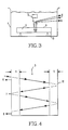
- the second ultrasonic approach uses a longitudinal wave transducer 5 (for example having a diameter of 1.27 cm [0.5 inch] ) immersed in tank 4 directly above specimen 3, in this example a plate, and in place of the transmitter-receiver pair used for the interface wave test.
- transducer 5 is oriented such that its ultrasonic output strikes the near, or first, surface of specimen 3 at essentially normal incidence to the surface; a two-transducer transmit-receive system could also be used, enabling the wave to be transmitted and received at other than normal incidence.
- a pulse-echo method is used.
- Figure 3 identifies the first three echoes received by transducer 5. Of course, more echoes will result, but only three are shown for simplicity.
- Reference numeral 6 represents the portion of the transmitted beam that echoes from first or near surface 9 of the sample
- reference numeral 7 identifies the first echo from the remote, or second, surface 10
- reference numeral 8 identifies the second echo from second surface 10 (after having internally reflected at first surface 9).
- the amplitude of each echo is related to the average acoustic properties of the specimen, and is therefore dependent on variations of acoustic properties due to scattering losses in the IGA layers at its first and second surfaces 9 and 10, respectively. Such variations are shown in the calculations below, which have been derived from known plane wave theory.
- amplitude of initial near surface echo RS1 amplitude of transmissive beam: S′1e - ⁇ d 1 ⁇ 1-R2 amplitude of first remote surface echo: S′1e - ⁇ (d 1 + 2d 2 ) ⁇ 1-R2 RS2 amplitude of first received transmissive beam: (1-R2) S1′2RS2e -2 ⁇ (d 1 + d 2 ) amplitude of first near surface internally reflected beam: S1′2S1S2e - ⁇ (3d 1 + 2d 2 ) ⁇ 1-R2 amplitude of second remote surface echo: S1′R3S1S22e - ⁇ (3d 1 + 4d 2 ) ⁇ 1-R2 amplitude of second received transmissive beam: (1-R2)S1′2R3S1S22e -4 ⁇ (d 1 + d 2 ) where: S1, S1′, S2, and S2′ are back- and forward-scattering losses for first and second IGA
- the decibel ratio of the amplitudes of the second-to-first surface echo returns is then calculated to be: -20 [log10 (e -2 ⁇ d 1 RS1) + log10 (e - ⁇ d 2 RS2)]
- the total measured decibel ratio is the sum of two independent contributions--one from first surface 9 and one from the second surface 10.
- the depth of IGA on the second surface 10 can be inferred from measurements made on only first surface 9 whenever the first term can be quantified, as set forth below.
- the method, then, for estimating the depth of a layer of IGA in second surface 10 is to first measure the interface wave attenuation decibel ratio for first surface 9, find its value on the ordinate of the graph shown in Figure 2, and then obtain from the trace Y the depth of IGA in first surface 9.
- the total reverberation echo decibel ratio of second surface 10 to first surface 9 is next measured using the single transducer system outlined above.
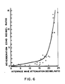
- the first surface interface wave attenuation decibel ratio is then converted to a reverberation echo decibel ratio using the graph shown in Figure 6.
- This graph represents a plot of reverberation echo decibel ratio to interface wave attenuation decibel ratio that is derived empirically. The value thus obtained represents the first surface contribution to the total reverberation echo decibel ratio found experimentally.
- Subtracting the first surface contribution from the total reverberation echo decibel ratio gives the contribution from second surface 10.
- the second surface interface wave decibel ratio may be estimated from the second surface contribution to the total reverberation echo decibel ratio.
- the depth of IGA in second surface 10 may be estimated from this value for second surface interface wave attenuation decibel ratio.
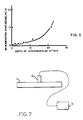
- the second surface IGA may be found using the graphical data of Figure 5 rather than that of Figure 6.
- the total depth of IGA for the two surfaces 9 and 10 (d1 + d2) may be estimated from the experimentally-determined total reverberation echo decibel ratio. The previously-derived value for d1 may then be subtracted from the estimated sum, leaving d2.
- Eddy current techniques for confirming measurements of first-surface depth of intergranular attack may be used to verify the ultrasonic interface wave test results.
- Figure 7 illustrates a known eddy current approach which uses a standard off-the-shelf probe at a frequency of 100 kHz in a surface-riding technique.
- the approach uses a standard eddy current instrument 14 connected with the above-described probes, which is laid flat on the surface being interrogated.
- a thin layer of Teflon tape (not shown) may be added as a wear surface for the probe.
Landscapes
- Chemical & Material Sciences (AREA)
- Physics & Mathematics (AREA)
- Health & Medical Sciences (AREA)
- Life Sciences & Earth Sciences (AREA)
- General Physics & Mathematics (AREA)
- Analytical Chemistry (AREA)
- Biochemistry (AREA)
- General Health & Medical Sciences (AREA)
- Immunology (AREA)
- Pathology (AREA)
- Acoustics & Sound (AREA)
- Crystallography & Structural Chemistry (AREA)
- Engineering & Computer Science (AREA)
- Food Science & Technology (AREA)
- Medicinal Chemistry (AREA)
- Investigating Or Analyzing Materials By The Use Of Ultrasonic Waves (AREA)
- Length Measuring Devices Characterised By Use Of Acoustic Means (AREA)
Applications Claiming Priority (2)
| Application Number | Priority Date | Filing Date | Title |
|---|---|---|---|
| US163360 | 1988-03-02 | ||
| US07/163,360 US4854173A (en) | 1988-03-02 | 1988-03-02 | Measurement of intergranular attack in stainless steel using ultrasonic energy |
Publications (2)
| Publication Number | Publication Date |
|---|---|
| EP0330735A2 true EP0330735A2 (de) | 1989-09-06 |
| EP0330735A3 EP0330735A3 (de) | 1990-07-18 |
Family
ID=22589696
Family Applications (1)
| Application Number | Title | Priority Date | Filing Date |
|---|---|---|---|
| EP88118692A Withdrawn EP0330735A3 (de) | 1988-03-02 | 1988-11-10 | Messung des Angriffs zwischen Körnern in rostfreiem Stahl mit Ultraschall |
Country Status (4)
| Country | Link |
|---|---|
| US (1) | US4854173A (de) |
| EP (1) | EP0330735A3 (de) |
| JP (1) | JPH0210261A (de) |
| KR (1) | KR890015015A (de) |
Cited By (3)
| Publication number | Priority date | Publication date | Assignee | Title |
|---|---|---|---|---|
| DE19513312C1 (de) * | 1995-04-03 | 1996-06-27 | Mannesmann Ag | Verfahren und Vorrichtung zur zerstörungsfreien Ermittlung von Eigenschaften eines Werkstückes aus Metall |
| CN104807881A (zh) * | 2014-01-26 | 2015-07-29 | 上海华林工业气体有限公司 | 一种薄壁氢气管线焊缝上氢致延迟裂纹的检测方法 |
| WO2017203166A1 (fr) | 2016-05-25 | 2017-11-30 | Electricite De France | Procede de detection par ultrasons de defauts dans un materiau |
Families Citing this family (8)
| Publication number | Priority date | Publication date | Assignee | Title |
|---|---|---|---|---|
| US5894092A (en) * | 1996-09-27 | 1999-04-13 | Industrial Quality, Inc. | Method and system for obtaining near-surface characteristics of materials using ultrasonic Rayleigh waves |
| US5767408A (en) * | 1996-09-27 | 1998-06-16 | Industrial Quality, Inc. | Method and system for obtaining near-surface characteristics of materials using ultrasonic Rayleigh waves |
| AU2002222955A1 (en) | 2000-07-14 | 2002-01-30 | Lockheed Martin Corporation | A system and method of determining porosity in composite materials using ultrasound |
| US6732587B2 (en) * | 2002-02-06 | 2004-05-11 | Lockheed Martin Corporation | System and method for classification of defects in a manufactured object |
| US20090252987A1 (en) * | 2008-04-02 | 2009-10-08 | United Technologies Corporation | Inspection and repair process using thermal acoustic imaging |
| CN103323525A (zh) * | 2013-05-21 | 2013-09-25 | 广东电网公司电力科学研究院 | 检测超级奥氏体不锈钢晶间腐蚀的非线性超声系统及方法 |
| CN103293225B (zh) * | 2013-05-28 | 2015-01-07 | 国家电网公司 | 锅炉水冷壁管氢损伤超声波检测与诊断方法 |
| CN109059813B (zh) * | 2018-07-19 | 2020-07-24 | 上海市特种设备监督检验技术研究院 | 一种起重机械钢结构腐蚀强度检测方法 |
Family Cites Families (15)
| Publication number | Priority date | Publication date | Assignee | Title |
|---|---|---|---|---|
| US3946600A (en) * | 1973-12-26 | 1976-03-30 | Lockheed Aircraft Corporation | Acoustic emission method for detection and monitoring of corrosion |
| US3939404A (en) * | 1974-07-10 | 1976-02-17 | Dominion Foundries And Steel, Limited | Method of testing for and preventing the possibility of cracking, spalling or like defects in rolling mill rolls by determining the rate of change in hardness |
| US4184373A (en) * | 1975-10-22 | 1980-01-22 | Vought Corporation | Apparatus for evaluating a bond |
| US4450405A (en) * | 1980-07-14 | 1984-05-22 | The Boeing Company | Alloy testing apparatus using eddy current conductivity probe |
| DE3036951C2 (de) * | 1980-09-30 | 1982-11-25 | Kraftwerk Union AG, 4330 Mülheim | Verfahren zur Schallemissionsprüfung von aus Stahl bestehenden Behältern oder Rohrleitungen, insbesondere für Kernreaktoranlagen |
| US4393711A (en) * | 1980-11-13 | 1983-07-19 | Electric Power Research Institute, Inc. | Apparatus and method for ultrasonic detection of flaws in power plant piping systems |
| US4366713A (en) * | 1981-03-25 | 1983-01-04 | General Electric Company | Ultrasonic bond testing of semiconductor devices |
| US4461995A (en) * | 1981-10-29 | 1984-07-24 | Republic Steel Corporation | Cooling method and apparatus for eddy current flaw detection |
| US4449408A (en) * | 1982-04-22 | 1984-05-22 | Magnetic Analysis Corporation | EMAT Test apparatus having retractable probe |
| US4449411A (en) * | 1982-04-22 | 1984-05-22 | Magnetic Analysis Corporation | Magnetic and ultrasonic objects testing apparatus |
| US4466287A (en) * | 1982-11-04 | 1984-08-21 | Fraunhofer-Gesellschaft Zur Forderung Der Angewandten Forschung E.V. | Non-destructive, non-contact ultrasonic material |
| GB8318606D0 (en) * | 1983-07-08 | 1983-08-10 | Atomic Energy Authority Uk | Ultrasonic resonance for detecting changes in elastic properties |
| US4522064A (en) * | 1983-12-12 | 1985-06-11 | Sigma Research Inc. | Ultrasonic method and apparatus for determining the depth of a crack in a solid material |
| DE3414362A1 (de) * | 1984-04-16 | 1985-10-17 | Kraftwerk Union AG, 4330 Mülheim | Verfahren zur ultraschall-pruefung von bolzen mit einem wanddickensprung |
| US4685334A (en) * | 1986-01-27 | 1987-08-11 | The Babcock & Wilcox Company | Method for ultrasonic detection of hydrogen damage in boiler tubes |
-
1988
- 1988-03-02 US US07/163,360 patent/US4854173A/en not_active Expired - Fee Related
- 1988-11-10 EP EP88118692A patent/EP0330735A3/de not_active Withdrawn
- 1988-12-09 KR KR1019880016401A patent/KR890015015A/ko not_active Withdrawn
-
1989
- 1989-03-02 JP JP1051836A patent/JPH0210261A/ja active Pending
Cited By (8)
| Publication number | Priority date | Publication date | Assignee | Title |
|---|---|---|---|---|
| DE19513312C1 (de) * | 1995-04-03 | 1996-06-27 | Mannesmann Ag | Verfahren und Vorrichtung zur zerstörungsfreien Ermittlung von Eigenschaften eines Werkstückes aus Metall |
| EP0737861A1 (de) * | 1995-04-03 | 1996-10-16 | MANNESMANN Aktiengesellschaft | Verfahren und Vorrichtung zur zerstörungsfreien Ermittlung von Eigenschaften eines Werkstückes aus Metall |
| CN104807881A (zh) * | 2014-01-26 | 2015-07-29 | 上海华林工业气体有限公司 | 一种薄壁氢气管线焊缝上氢致延迟裂纹的检测方法 |
| WO2017203166A1 (fr) | 2016-05-25 | 2017-11-30 | Electricite De France | Procede de detection par ultrasons de defauts dans un materiau |
| FR3051913A1 (fr) * | 2016-05-25 | 2017-12-01 | Electricite De France | Procede de detection par ultrasons de defauts dans un materiau |
| CN109196350A (zh) * | 2016-05-25 | 2019-01-11 | 法国电力公司 | 通过超声检测材料中的缺陷的方法 |
| CN109196350B (zh) * | 2016-05-25 | 2020-01-14 | 法国电力公司 | 通过超声检测材料中的缺陷的方法 |
| US10551352B2 (en) | 2016-05-25 | 2020-02-04 | Electricite De France | Method for detecting defects in a material by ultrasounds |
Also Published As
| Publication number | Publication date |
|---|---|
| KR890015015A (ko) | 1989-10-28 |
| EP0330735A3 (de) | 1990-07-18 |
| US4854173A (en) | 1989-08-08 |
| JPH0210261A (ja) | 1990-01-16 |
Similar Documents
| Publication | Publication Date | Title |
|---|---|---|
| Krause et al. | Comparison of pulse-echo methods for testing concrete | |
| Cawley et al. | The use of Lamb waves for the long range inspection of large structures | |
| CN101398409B (zh) | 斜入射体波技术钢板自动检测方法及其装置 | |
| CA2258439C (en) | Ultrasonic lamb wave technique for measurement of pipe wall thickness at pipe supports | |
| US7389693B2 (en) | Methods and apparatus for porosity measurement | |
| US5661241A (en) | Ultrasonic technique for measuring the thickness of cladding on the inside surface of vessels from the outside diameter surface | |
| JP4116483B2 (ja) | 管体の超音波探傷検査方法および装置 | |
| EP0642015A1 (de) | Verfahren und Vorrichtung zur Messung und Regelung der refraktierten Winkel von Ultraschallwellen | |
| JPH0352908B2 (de) | ||
| US4854173A (en) | Measurement of intergranular attack in stainless steel using ultrasonic energy | |
| GB2153531A (en) | Ultrasonic inspection of tube to tube plate welds | |
| CN112326799A (zh) | 相控阵技术在压力管道定期检验评级中应用的方法 | |
| US5404754A (en) | Ultrasonic detection of high temperature hydrogen attack | |
| CA2012374C (en) | Ultrasonic crack sizing method | |
| KR100966543B1 (ko) | 유도 초음파를 이용한 배관 내부 침적층 평가 장치 | |
| JP2004077292A (ja) | 応力腐食割れ検査方法及び検査装置 | |
| JP2002277447A (ja) | 超音波探傷方法および装置 | |
| JPH1194806A (ja) | 鋼材端部表面又は側面の超音波探傷方法 | |
| JPH08271488A (ja) | Frpm管の材質評価方法 | |
| CN117665131A (zh) | 一种钢轨焊缝损伤检测方法 | |
| JP4761147B2 (ja) | 超音波探傷方法及び装置 | |
| CN115616092A (zh) | 一种焊缝缺陷检测方法及其装置 | |
| Fortunko et al. | Evaluation of pipeline girth welds using low-frequency horizontally polarized waves | |
| Jiang et al. | Simulation of modified absolute arrival time technique for measuring surface breaking cracks | |
| KR19990048190A (ko) | 고체재료의 두께 및 초음파 속도를 동시에 측정하는 장치 및 방법 |
Legal Events
| Date | Code | Title | Description |
|---|---|---|---|
| PUAI | Public reference made under article 153(3) epc to a published international application that has entered the european phase |
Free format text: ORIGINAL CODE: 0009012 |
|
| AK | Designated contracting states |
Kind code of ref document: A2 Designated state(s): BE CH ES FR GB IT LI |
|
| PUAL | Search report despatched |
Free format text: ORIGINAL CODE: 0009013 |
|
| AK | Designated contracting states |
Kind code of ref document: A3 Designated state(s): BE CH ES FR GB IT LI |
|
| 17P | Request for examination filed |
Effective date: 19900818 |
|
| STAA | Information on the status of an ep patent application or granted ep patent |
Free format text: STATUS: THE APPLICATION HAS BEEN WITHDRAWN |
|
| 18W | Application withdrawn |
Withdrawal date: 19910925 |
|
| R18W | Application withdrawn (corrected) |
Effective date: 19910925 |