EP0330744A2 - Système de verrouillage - Google Patents
Système de verrouillage Download PDFInfo
- Publication number
- EP0330744A2 EP0330744A2 EP88120111A EP88120111A EP0330744A2 EP 0330744 A2 EP0330744 A2 EP 0330744A2 EP 88120111 A EP88120111 A EP 88120111A EP 88120111 A EP88120111 A EP 88120111A EP 0330744 A2 EP0330744 A2 EP 0330744A2
- Authority
- EP
- European Patent Office
- Prior art keywords
- workpiece
- arm
- locking
- elongated
- accordance
- Prior art date
- Legal status (The legal status is an assumption and is not a legal conclusion. Google has not performed a legal analysis and makes no representation as to the accuracy of the status listed.)
- Granted
Links
Images


Classifications
-
- F—MECHANICAL ENGINEERING; LIGHTING; HEATING; WEAPONS; BLASTING
- F16—ENGINEERING ELEMENTS AND UNITS; GENERAL MEASURES FOR PRODUCING AND MAINTAINING EFFECTIVE FUNCTIONING OF MACHINES OR INSTALLATIONS; THERMAL INSULATION IN GENERAL
- F16B—DEVICES FOR FASTENING OR SECURING CONSTRUCTIONAL ELEMENTS OR MACHINE PARTS TOGETHER, e.g. NAILS, BOLTS, CIRCLIPS, CLAMPS, CLIPS OR WEDGES; JOINTS OR JOINTING
- F16B21/00—Means for preventing relative axial movement of a pin, spigot, shaft or the like and a member surrounding it; Stud-and-socket releasable fastenings
- F16B21/06—Releasable fastening devices with snap-action
- F16B21/07—Releasable fastening devices with snap-action in which the socket has a resilient part
- F16B21/071—Releasable fastening devices with snap-action in which the socket has a resilient part the socket being integrally formed with a component to be fasted, e.g. a sheet, plate or strip
-
- F—MECHANICAL ENGINEERING; LIGHTING; HEATING; WEAPONS; BLASTING
- F16—ENGINEERING ELEMENTS AND UNITS; GENERAL MEASURES FOR PRODUCING AND MAINTAINING EFFECTIVE FUNCTIONING OF MACHINES OR INSTALLATIONS; THERMAL INSULATION IN GENERAL
- F16B—DEVICES FOR FASTENING OR SECURING CONSTRUCTIONAL ELEMENTS OR MACHINE PARTS TOGETHER, e.g. NAILS, BOLTS, CIRCLIPS, CLAMPS, CLIPS OR WEDGES; JOINTS OR JOINTING
- F16B21/00—Means for preventing relative axial movement of a pin, spigot, shaft or the like and a member surrounding it; Stud-and-socket releasable fastenings
- F16B21/06—Releasable fastening devices with snap-action
-
- H—ELECTRICITY
- H05—ELECTRIC TECHNIQUES NOT OTHERWISE PROVIDED FOR
- H05K—PRINTED CIRCUITS; CASINGS OR CONSTRUCTIONAL DETAILS OF ELECTRIC APPARATUS; MANUFACTURE OF ASSEMBLAGES OF ELECTRICAL COMPONENTS
- H05K5/00—Casings, cabinets or drawers for electric apparatus
- H05K5/10—Casings, cabinets or drawers for electric apparatus comprising several parts forming a closed casing
- H05K5/15—Casings, cabinets or drawers for electric apparatus comprising several parts forming a closed casing assembled by resilient members
-
- F—MECHANICAL ENGINEERING; LIGHTING; HEATING; WEAPONS; BLASTING
- F16—ENGINEERING ELEMENTS AND UNITS; GENERAL MEASURES FOR PRODUCING AND MAINTAINING EFFECTIVE FUNCTIONING OF MACHINES OR INSTALLATIONS; THERMAL INSULATION IN GENERAL
- F16B—DEVICES FOR FASTENING OR SECURING CONSTRUCTIONAL ELEMENTS OR MACHINE PARTS TOGETHER, e.g. NAILS, BOLTS, CIRCLIPS, CLAMPS, CLIPS OR WEDGES; JOINTS OR JOINTING
- F16B2200/00—Constructional details of connections not covered for in other groups of this subclass
- F16B2200/20—Connections with hook-like parts gripping behind a blind side of an element to be connected
- F16B2200/205—Connections with hook-like parts gripping behind a blind side of an element to be connected the hook being a separate retainer
-
- F—MECHANICAL ENGINEERING; LIGHTING; HEATING; WEAPONS; BLASTING
- F16—ENGINEERING ELEMENTS AND UNITS; GENERAL MEASURES FOR PRODUCING AND MAINTAINING EFFECTIVE FUNCTIONING OF MACHINES OR INSTALLATIONS; THERMAL INSULATION IN GENERAL
- F16B—DEVICES FOR FASTENING OR SECURING CONSTRUCTIONAL ELEMENTS OR MACHINE PARTS TOGETHER, e.g. NAILS, BOLTS, CIRCLIPS, CLAMPS, CLIPS OR WEDGES; JOINTS OR JOINTING
- F16B2200/00—Constructional details of connections not covered for in other groups of this subclass
- F16B2200/69—Redundant disconnection blocking means
-
- Y—GENERAL TAGGING OF NEW TECHNOLOGICAL DEVELOPMENTS; GENERAL TAGGING OF CROSS-SECTIONAL TECHNOLOGIES SPANNING OVER SEVERAL SECTIONS OF THE IPC; TECHNICAL SUBJECTS COVERED BY FORMER USPC CROSS-REFERENCE ART COLLECTIONS [XRACs] AND DIGESTS
- Y10—TECHNICAL SUBJECTS COVERED BY FORMER USPC
- Y10T—TECHNICAL SUBJECTS COVERED BY FORMER US CLASSIFICATION
- Y10T24/00—Buckles, buttons, clasps, etc.
- Y10T24/45—Separable-fastener or required component thereof [e.g., projection and cavity to complete interlock]
- Y10T24/45225—Separable-fastener or required component thereof [e.g., projection and cavity to complete interlock] including member having distinct formations and mating member selectively interlocking therewith
- Y10T24/45471—Projection having movable connection between components thereof or variable configuration
- Y10T24/45524—Projection having movable connection between components thereof or variable configuration including resiliently biased projection component or surface segment
- Y10T24/45545—Projection having movable connection between components thereof or variable configuration including resiliently biased projection component or surface segment forming total external surface of projection
- Y10T24/45581—Projection having movable connection between components thereof or variable configuration including resiliently biased projection component or surface segment forming total external surface of projection having inserted end formed by oppositely biased surface segments
-
- Y—GENERAL TAGGING OF NEW TECHNOLOGICAL DEVELOPMENTS; GENERAL TAGGING OF CROSS-SECTIONAL TECHNOLOGIES SPANNING OVER SEVERAL SECTIONS OF THE IPC; TECHNICAL SUBJECTS COVERED BY FORMER USPC CROSS-REFERENCE ART COLLECTIONS [XRACs] AND DIGESTS
- Y10—TECHNICAL SUBJECTS COVERED BY FORMER USPC
- Y10T—TECHNICAL SUBJECTS COVERED BY FORMER US CLASSIFICATION
- Y10T24/00—Buckles, buttons, clasps, etc.
- Y10T24/45—Separable-fastener or required component thereof [e.g., projection and cavity to complete interlock]
- Y10T24/45225—Separable-fastener or required component thereof [e.g., projection and cavity to complete interlock] including member having distinct formations and mating member selectively interlocking therewith
- Y10T24/45602—Receiving member includes either movable connection between interlocking components or variable configuration cavity
- Y10T24/45775—Receiving member includes either movable connection between interlocking components or variable configuration cavity having resiliently biased interlocking component or segment
- Y10T24/45785—Requiring manual force applied against bias to interlock or disengage
-
- Y—GENERAL TAGGING OF NEW TECHNOLOGICAL DEVELOPMENTS; GENERAL TAGGING OF CROSS-SECTIONAL TECHNOLOGIES SPANNING OVER SEVERAL SECTIONS OF THE IPC; TECHNICAL SUBJECTS COVERED BY FORMER USPC CROSS-REFERENCE ART COLLECTIONS [XRACs] AND DIGESTS
- Y10—TECHNICAL SUBJECTS COVERED BY FORMER USPC
- Y10T—TECHNICAL SUBJECTS COVERED BY FORMER US CLASSIFICATION
- Y10T403/00—Joints and connections
- Y10T403/16—Joints and connections with adjunctive protector, broken parts retainer, repair, assembly or disassembly feature
- Y10T403/1616—Position or guide means
- Y10T403/1624—Related to joint component
Definitions
- This invention relates to systems and techniques for detachably securing two items together. More particularly, this invention relates to systems and techniques for detach severelyably securing two workpieces together (e.g., two sections of a housing).
- housing sections used to enclose or contain a product must be fastened in some manner so as to be secure when the product is used, but preferably the housing sections are detachable so that they can be removed to allow access to the product (e.g., for repair purposes).
- Such products require the type of enclosure or containment described.
- Such products include, for example, gears, electronics, linkages, tubing or wiring which must be clamped or secured in place, and other various mechanisms.
- the workpieces may be housings for electrical components, mounting or clamping devices, or locating components of a mechanical gear train or linkage.
- fastening devices can be used to detachably secure items such as housing sections to each other or to a product to be enclosed.
- various types of threaded fasteners or other mechanical fasteners have been used for this purpose.
- this requires that additional components be used, thereby increasing the cost of the enclosure.
- hook and loop fasteners such as Velcro brand fasteners
- over-center latches such as Velcro brand fasteners
- press fit fasteners e.g., where a post is pushed into an opening with great force to frictionally engage the walls of the opening.
- Hook and loop fasteners have structural limitations. Latches can be complex and also costly. Press fit fasteners may lose their effectiveness after being detached one or more times.
- a locking system for detachably securing two workpieces such as housing sections together.
- the locking system comprises:
- the second end of the elongated arm can be deflected by the lead in ramp means when the first workpiece is urged toward the second workpiece. This enables the second end of the elongated arm to pass through the opening.
- the locking arm is movable to its closed position behind the second end of the elongated arm to restrict movement of the second end.
- the hook portion or engagement means on the end of the elongated arm engages the second workpiece. The locking arm prevents the hook portion of the elongated arm from backing out of the opening in the second workpiece when the elongated arm is loaded in tension, thereby preventing the previously-described failure.
- Unlocking requires that the locking arm be moved from its closed to its open position. Then the second end of the elongated arm can be deflected so that the hook portion or engagement means is released from the second workpiece, allowing the elongated arm to be moved out of the opening in the second workpiece.
- elongated arms carried by the first workpiece and a corresponding plurality of openings in the second workpieces.
- the two workpieces may be housing sections which are used to enclose a product (e.g., a gear train, electronics system, etc.)
- a product e.g., a gear train, electronics system, etc.
- the locking system illustrated includes pairs of elongated, parallel arms 12 and 14. At one end the parallel arms are secured to one of the workpieces 40. Preferably, the arms are integrally molded as a part of the workpiece 40. Alternatively, the arms could be attached to the workpiece with adhesive or other fasteners.
- the second workpiece 50 includes a plurality of openings 18 corresponding to rhe number of pairs of parallel arms carried by the first workpiece 40.
- the locking arm is integral with the work piece at one end in a manner such that the opposite end of the locking arm is deflectable out of the opening but will return to its normal position within the opening.
- the outer ends of the elongated arms 12 and 14 include hook portions 13 and 15, respectively.
- the outer ends of the arms are resiliently deflectable so that they may be urged towards each other to fit within the corresponding opening in the second workpiece Then the arms spring away from each other again in a manner such that the hook portions 13 and 15 engage the second workpiece.
- the locking arm can then deflect back to its closed position where it is situated between the ends of the elongated arms to restrict movement of the ends towards each other.
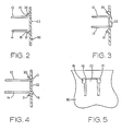
- Figures 2-5 These features are illustrated in Figures 2-5.
- the outer ends of the elongated arms 12 and 14 are shown contacting the lead in ramp members 20 and 21, respectively, which are located adjacent opposite side edges of opening 18.
- the lead in ramp members serve as guide members to urge the outer ends of the elongated arms towards each other when the first workpiece 40 is moved toward the second workpiece 50.
- the locking arm prevents the elongated arms from coming loose from the second workpiece when tension is applied to the elongated arms. Yet the two workpieces can be easily separated from each other when desired by first moving each locking arm 22 away from the ends of the arms 12 and 14 to allow them to be moved towards each other. In this manner the hook portions are disengaged from the second workpiece.
- side walls 23 and 24 of workpiece 40 serve to establish the desired minimum spacing between the two workpieces. Thus, when the sidewalls contact the other workpiece the desired spacing is maintained.
- FIG. 7 Another manner of establishing the desired spacing between the two workpieces is illustrated in Figure 7.
- the other workpiece 70 includes an opening 71 in which a locking arm 72 is disposed.
- Ramp member 74 is carried by workpiece 70 adjacent one edge of opening 71.
- ramp member 74 guides the end of arm 60 into opening 71 where it deflects the upper end of locking arm 72 out of opening 71. Then when the end of arm 60 is through opening 71, locking arm 72 springs back behind arm 60 so that hook member 62 remains in engagement with workpiece 70.
- Ledge or stop member 64 on arm 60 serves to limit the extent to which arm 60 may pass through opening 71. In this manner the minimum spacing between the two workpieces is maintained.
- Positional alignment between the two workpieces may be provided by referencing pins 25 on one workpiece and alignment apertures 26 on the other workpiece, as illustrated in Figure 1. Such alignment is not required in all cases but it may be helpful in situations where a high degree of positional accuracy is required.
- Figure 6 illustrates another embodiment of the locking system of this invention.
- One workpiece 30 includes opening 31.
- Locking arm 33 is disposed in opening 31, as illustrated.
- Ramp member 32 is carried by workpiece 30 adjacent the top edge of opening 31.
- An elongated arm 42 carried by another workpiece (not shown) is adapted to pass through opening 31 in workpiece 30.
- the outer or free end of arm 42 includes an upstanding wall or hook member 43 which is adapted to engage the outer surface of workpiece 30 after it has been passed through opening 31.
- the leading end of arm 42 includes a ramp member 44 to assist in guiding this end of arm 42 into opening 31 when the two workpieces are brought together.
- Locking arm 33 is deflected out of opening 31 by the end of arm 42. Then arm 33 springs back into its original position where it holds arm 42 against the upper edge of opening 31. This assures that hook portion 43 is maintained in engagement with workpiece 30.
- the locking arm 33 is deflected out of the way. Then the arm 42 can be deflected downwardly so that the hook member 43 is disengaged from workpiece 30. At that point the arm 42 may be moved out of opening 31.
- two of the arms may be adapted to engage the second workpiece along side edges of the opening while the third arm is adapted to enage the second workpiece along the top edge of the opening.
Landscapes
- Engineering & Computer Science (AREA)
- General Engineering & Computer Science (AREA)
- Mechanical Engineering (AREA)
- Microelectronics & Electronic Packaging (AREA)
- Clamps And Clips (AREA)
- Insertion Pins And Rivets (AREA)
- Snaps, Bayonet Connections, Set Pins, And Snap Rings (AREA)
- Jigs For Machine Tools (AREA)
- Connection Of Plates (AREA)
Applications Claiming Priority (2)
| Application Number | Priority Date | Filing Date | Title |
|---|---|---|---|
| US07/161,560 US4844645A (en) | 1988-02-29 | 1988-02-29 | Locking system |
| US161560 | 1988-02-29 |
Publications (3)
| Publication Number | Publication Date |
|---|---|
| EP0330744A2 true EP0330744A2 (fr) | 1989-09-06 |
| EP0330744A3 EP0330744A3 (en) | 1990-08-01 |
| EP0330744B1 EP0330744B1 (fr) | 1994-02-16 |
Family
ID=22581695
Family Applications (1)
| Application Number | Title | Priority Date | Filing Date |
|---|---|---|---|
| EP88120111A Expired - Lifetime EP0330744B1 (fr) | 1988-02-29 | 1988-12-02 | Système de verrouillage |
Country Status (8)
| Country | Link |
|---|---|
| US (1) | US4844645A (fr) |
| EP (1) | EP0330744B1 (fr) |
| JP (1) | JP2664461B2 (fr) |
| KR (1) | KR0131076B1 (fr) |
| CN (1) | CN1015490B (fr) |
| CA (1) | CA1304909C (fr) |
| DE (1) | DE3887872T2 (fr) |
| SG (1) | SG5295G (fr) |
Cited By (5)
| Publication number | Priority date | Publication date | Assignee | Title |
|---|---|---|---|---|
| DE29621207U1 (de) * | 1996-12-06 | 1997-01-30 | MAN Roland Druckmaschinen AG, 63075 Offenbach | Befestigung eines Kühlkörpers auf einer Flachbaugruppe |
| DE29618497U1 (de) * | 1996-10-23 | 1998-02-19 | Hagus C. Luchtenberg Gmbh & Co Kg, 42719 Solingen | Rastverbindung |
| EP0838598A3 (fr) * | 1996-10-23 | 1999-04-28 | HAGUS C. LUCHTENBERG GmbH & Co. KG | Système d'assemblage par encliquetage |
| EP1111976A1 (fr) * | 1999-12-21 | 2001-06-27 | Nokia Mobile Phones Ltd. | Dispositif d'encliquetage |
| WO2023025593A1 (fr) * | 2021-08-24 | 2023-03-02 | Valeo Vision | Structure de liaison par encliquetage, dispositif d'éclairage et véhicule |
Families Citing this family (21)
| Publication number | Priority date | Publication date | Assignee | Title |
|---|---|---|---|---|
| US5213776A (en) * | 1989-09-12 | 1993-05-25 | Gerber Products Company | Sterilizer for infant accessories |
| FR2665493B1 (fr) * | 1990-08-03 | 1992-09-18 | Merlin Gerin | Assemblage indemontable par encliquetage. |
| US5267656A (en) * | 1992-07-10 | 1993-12-07 | Nichols David G | Display stand apparatus |
| DE29603824U1 (de) * | 1996-03-01 | 1996-05-23 | Vorwerk & Co Interholding Gmbh, 42275 Wuppertal | Schnapp-Passe zur Verrastung von mindestens zwei Fügepartnern |
| DE19612843A1 (de) * | 1996-03-30 | 1997-10-02 | Telefunken Microelectron | Gehäuse mit Mittel zur Befestigung auf einer Befestigungsplatte |
| FR2765641B1 (fr) * | 1997-07-03 | 1999-09-24 | Magneti Marelli France | Dispositif de fixation perfectionne pour organe d'affichage de vehicule automobile |
| JPH11112161A (ja) | 1997-09-30 | 1999-04-23 | Fujitsu Ltd | ロック機構、装置の筐体構造、装置固定機構及びガラス固定機構 |
| US6012400A (en) * | 1998-03-26 | 2000-01-11 | Stein Industries, Inc. | Shelving support pin |
| US6732557B1 (en) * | 2002-02-15 | 2004-05-11 | Raymond E. Zehrung | Electrified mortise lock having a solenoid cradle |
| GB2386742B (en) * | 2002-03-20 | 2004-02-11 | Amersham Plc | Radioisotope generator component support |
| CN101233796B (zh) * | 2005-07-27 | 2012-09-05 | 日本电气株式会社 | 电子设备以及该电子设备用的框体 |
| KR100798782B1 (ko) * | 2006-10-31 | 2008-01-29 | 삼성전자주식회사 | 결합용 후크장치 및 이를 갖춘 세탁기 |
| CN102345617B (zh) * | 2010-07-28 | 2015-05-27 | 广东松下环境系统有限公司 | 换气扇 |
| EP2737148B1 (fr) * | 2011-07-27 | 2016-11-02 | Husqvarna AB | Caractéristique d'encliquetage permettant la fixation d'un élément |
| CN104324812B (zh) * | 2013-07-22 | 2017-03-15 | 珠海格力电器股份有限公司 | 净化部件安装架及具有其的空气净化器 |
| BE1025776B1 (fr) * | 2017-12-12 | 2019-07-11 | Schreder S.A. | Ensemble de fermeture perfectionné |
| DE102020208560A1 (de) * | 2020-07-08 | 2022-01-13 | Mahle International Gmbh | Gehäuse |
| JP7648591B2 (ja) * | 2022-12-28 | 2025-03-18 | フタバ産業株式会社 | ユニットの取付構造 |
| US11857044B1 (en) * | 2023-06-20 | 2024-01-02 | Pioneer Square Brands, Inc. | Portable electronic device case |
| DE102024106640B3 (de) * | 2024-03-07 | 2025-09-04 | Motherson Innovations Company Limited | Scharnier- und/oder clip-anordnung, rückblick-anordnung und fahrzeug |
| US12075895B1 (en) * | 2024-05-09 | 2024-09-03 | Pioneer Square Brands, Inc. | Portable electronic device case accessory system |
Family Cites Families (8)
| Publication number | Priority date | Publication date | Assignee | Title |
|---|---|---|---|---|
| FR2211993A5 (fr) * | 1972-12-21 | 1974-07-19 | Itt Produits Ind | |
| JPS5088093A (fr) * | 1973-12-13 | 1975-07-15 | ||
| AU497454B2 (en) * | 1977-02-11 | 1978-12-14 | Newage Kitchens Limited | Furniture joint assembly |
| US4408373A (en) * | 1980-09-02 | 1983-10-11 | Gateway Industries, Inc. | Buckle with integral push button spring and reaction portions |
| DE3035669A1 (de) * | 1980-09-22 | 1982-04-08 | Bosch-Siemens Hausgeräte GmbH, 7000 Stuttgart | Geraet mit mindestens zwei mittels einesm rasthakens loesbar miteinander verbundenen teilen |
| DE8120432U1 (de) * | 1981-07-13 | 1981-12-24 | Fildan, Gerhard, Ing.(Grad.), 7250 Leonberg | Verschluss, insbesondere fuer kleidungsstuecke, gurte u. dergl. |
| GB8311064D0 (en) * | 1983-04-22 | 1983-05-25 | Y S Securities Ltd | Electrical assemblies |
| US4552540A (en) * | 1984-01-19 | 1985-11-12 | Eric Bass | Swimming pool exercise device |
-
1988
- 1988-02-29 US US07/161,560 patent/US4844645A/en not_active Expired - Fee Related
- 1988-11-18 CA CA000583556A patent/CA1304909C/fr not_active Expired - Lifetime
- 1988-12-02 EP EP88120111A patent/EP0330744B1/fr not_active Expired - Lifetime
- 1988-12-02 DE DE3887872T patent/DE3887872T2/de not_active Expired - Fee Related
- 1988-12-20 CN CN88105188A patent/CN1015490B/zh not_active Expired
-
1989
- 1989-02-28 JP JP1048428A patent/JP2664461B2/ja not_active Expired - Lifetime
- 1989-02-28 KR KR1019890002417A patent/KR0131076B1/ko not_active Expired - Fee Related
-
1995
- 1995-01-14 SG SG5295A patent/SG5295G/en unknown
Cited By (7)
| Publication number | Priority date | Publication date | Assignee | Title |
|---|---|---|---|---|
| DE29618497U1 (de) * | 1996-10-23 | 1998-02-19 | Hagus C. Luchtenberg Gmbh & Co Kg, 42719 Solingen | Rastverbindung |
| EP0838598A3 (fr) * | 1996-10-23 | 1999-04-28 | HAGUS C. LUCHTENBERG GmbH & Co. KG | Système d'assemblage par encliquetage |
| DE19732690C2 (de) * | 1996-10-23 | 2003-11-13 | Luchtenberg Gmbh & Co | Rastverbindung |
| DE29621207U1 (de) * | 1996-12-06 | 1997-01-30 | MAN Roland Druckmaschinen AG, 63075 Offenbach | Befestigung eines Kühlkörpers auf einer Flachbaugruppe |
| EP1111976A1 (fr) * | 1999-12-21 | 2001-06-27 | Nokia Mobile Phones Ltd. | Dispositif d'encliquetage |
| US6842633B1 (en) | 1999-12-21 | 2005-01-11 | Nokia Mobile Phones Ltd. | Clip arrangement for portable electronic apparatus housing assembly |
| WO2023025593A1 (fr) * | 2021-08-24 | 2023-03-02 | Valeo Vision | Structure de liaison par encliquetage, dispositif d'éclairage et véhicule |
Also Published As
| Publication number | Publication date |
|---|---|
| KR0131076B1 (ko) | 1998-04-11 |
| JPH01283418A (ja) | 1989-11-15 |
| CN1015490B (zh) | 1992-02-12 |
| SG5295G (en) | 1995-06-16 |
| EP0330744B1 (fr) | 1994-02-16 |
| EP0330744A3 (en) | 1990-08-01 |
| CN1035552A (zh) | 1989-09-13 |
| US4844645A (en) | 1989-07-04 |
| KR890012752A (ko) | 1989-09-19 |
| JP2664461B2 (ja) | 1997-10-15 |
| DE3887872T2 (de) | 1994-06-16 |
| CA1304909C (fr) | 1992-07-14 |
| DE3887872D1 (de) | 1994-03-24 |
Similar Documents
| Publication | Publication Date | Title |
|---|---|---|
| US4844645A (en) | Locking system | |
| US4669688A (en) | Cable clamp | |
| EP2811098B1 (fr) | Ensemble régulateur de fenêtre pour un véhicule | |
| EP0961362B1 (fr) | Structure de montage pour connecteur électrique | |
| US5788268A (en) | Spring retainer air bag mounting device | |
| US4845591A (en) | Device for holding an electronic equipment housing on a tray | |
| US7520481B2 (en) | Mounting assembly | |
| US5919057A (en) | Removable main connector | |
| EP3708031B1 (fr) | Dispositif de connexion | |
| US6262366B1 (en) | Housing including first and second housing halves, and an arrangement for locking thereof | |
| EP0167743B1 (fr) | Assemblage de pièces de construction pour un bâti d'imprimante | |
| US5711587A (en) | Cover mounting structure for shelf assembly | |
| GB1597451A (en) | Printed circuit packages of electrical components | |
| EP0104481B1 (fr) | Mécanisme de montage pour modules électriques à rebord | |
| EP0182361B1 (fr) | Dispositif d'affichage d'une image de grandes dimensions | |
| EP0098093A1 (fr) | Imprimante en série | |
| JPH068324Y2 (ja) | パネルの係着装置 | |
| EP0317277B1 (fr) | Ensemble réceptacle d'un équipement | |
| US6135825A (en) | Connector for detachable fastening to a rail | |
| EP0721237A2 (fr) | Connexion d'un grand nombre de signaux venant de systèmes électroniques vers des modules de test | |
| JPH06219219A (ja) | 音担体に用いられる容器 | |
| CN100344213C (zh) | 平面平行地固定两个模件的装置 | |
| JPH0631745Y2 (ja) | 電気機器のdinレール取付機構 | |
| JPS6260297A (ja) | 電気機器のレ−ル取付構造 | |
| WO2023067887A1 (fr) | Boucle |
Legal Events
| Date | Code | Title | Description |
|---|---|---|---|
| PUAI | Public reference made under article 153(3) epc to a published international application that has entered the european phase |
Free format text: ORIGINAL CODE: 0009012 |
|
| AK | Designated contracting states |
Kind code of ref document: A2 Designated state(s): DE FR GB IT |
|
| PUAL | Search report despatched |
Free format text: ORIGINAL CODE: 0009013 |
|
| AK | Designated contracting states |
Kind code of ref document: A3 Designated state(s): DE FR GB IT |
|
| 17P | Request for examination filed |
Effective date: 19910123 |
|
| 17Q | First examination report despatched |
Effective date: 19911217 |
|
| GRAA | (expected) grant |
Free format text: ORIGINAL CODE: 0009210 |
|
| AK | Designated contracting states |
Kind code of ref document: B1 Designated state(s): DE FR GB IT |
|
| ITF | It: translation for a ep patent filed | ||
| REF | Corresponds to: |
Ref document number: 3887872 Country of ref document: DE Date of ref document: 19940324 |
|
| ET | Fr: translation filed | ||
| PLBE | No opposition filed within time limit |
Free format text: ORIGINAL CODE: 0009261 |
|
| STAA | Information on the status of an ep patent application or granted ep patent |
Free format text: STATUS: NO OPPOSITION FILED WITHIN TIME LIMIT |
|
| 26N | No opposition filed | ||
| PGFP | Annual fee paid to national office [announced via postgrant information from national office to epo] |
Ref country code: FR Payment date: 19971119 Year of fee payment: 10 |
|
| PGFP | Annual fee paid to national office [announced via postgrant information from national office to epo] |
Ref country code: DE Payment date: 19971125 Year of fee payment: 10 |
|
| PGFP | Annual fee paid to national office [announced via postgrant information from national office to epo] |
Ref country code: GB Payment date: 19971126 Year of fee payment: 10 |
|
| PG25 | Lapsed in a contracting state [announced via postgrant information from national office to epo] |
Ref country code: GB Free format text: LAPSE BECAUSE OF NON-PAYMENT OF DUE FEES Effective date: 19981202 |
|
| GBPC | Gb: european patent ceased through non-payment of renewal fee |
Effective date: 19981202 |
|
| PG25 | Lapsed in a contracting state [announced via postgrant information from national office to epo] |
Ref country code: FR Free format text: LAPSE BECAUSE OF NON-PAYMENT OF DUE FEES Effective date: 19990831 |
|
| REG | Reference to a national code |
Ref country code: FR Ref legal event code: ST |
|
| PG25 | Lapsed in a contracting state [announced via postgrant information from national office to epo] |
Ref country code: DE Free format text: LAPSE BECAUSE OF NON-PAYMENT OF DUE FEES Effective date: 19991001 |
|
| PG25 | Lapsed in a contracting state [announced via postgrant information from national office to epo] |
Ref country code: IT Free format text: LAPSE BECAUSE OF NON-PAYMENT OF DUE FEES;WARNING: LAPSES OF ITALIAN PATENTS WITH EFFECTIVE DATE BEFORE 2007 MAY HAVE OCCURRED AT ANY TIME BEFORE 2007. THE CORRECT EFFECTIVE DATE MAY BE DIFFERENT FROM THE ONE RECORDED. Effective date: 20051202 |