EP0330794B1 - Drehkippfenster mit drei Öffnungsmöglichkeiten - Google Patents
Drehkippfenster mit drei Öffnungsmöglichkeiten Download PDFInfo
- Publication number
- EP0330794B1 EP0330794B1 EP88440058A EP88440058A EP0330794B1 EP 0330794 B1 EP0330794 B1 EP 0330794B1 EP 88440058 A EP88440058 A EP 88440058A EP 88440058 A EP88440058 A EP 88440058A EP 0330794 B1 EP0330794 B1 EP 0330794B1
- Authority
- EP
- European Patent Office
- Prior art keywords
- opening
- groove
- lug
- rods
- opening member
- Prior art date
- Legal status (The legal status is an assumption and is not a legal conclusion. Google has not performed a legal analysis and makes no representation as to the accuracy of the status listed.)
- Expired - Lifetime
Links
- 238000009423 ventilation Methods 0.000 claims abstract description 28
- 230000000903 blocking effect Effects 0.000 claims description 2
- 238000000034 method Methods 0.000 claims 5
- 238000006073 displacement reaction Methods 0.000 claims 2
- 239000011435 rock Substances 0.000 claims 1
- 239000002184 metal Substances 0.000 description 2
- 238000004140 cleaning Methods 0.000 description 1
- 238000003754 machining Methods 0.000 description 1
- 239000000463 material Substances 0.000 description 1
- 238000003801 milling Methods 0.000 description 1
- 239000004033 plastic Substances 0.000 description 1
- 239000002023 wood Substances 0.000 description 1
Images


Classifications
-
- E—FIXED CONSTRUCTIONS
- E05—LOCKS; KEYS; WINDOW OR DOOR FITTINGS; SAFES
- E05C—BOLTS OR FASTENING DEVICES FOR WINGS, SPECIALLY FOR DOORS OR WINDOWS
- E05C7/00—Fastening devices specially adapted for two wings
- E05C7/04—Fastening devices specially adapted for two wings for wings which abut when closed
-
- E—FIXED CONSTRUCTIONS
- E05—LOCKS; KEYS; WINDOW OR DOOR FITTINGS; SAFES
- E05C—BOLTS OR FASTENING DEVICES FOR WINGS, SPECIALLY FOR DOORS OR WINDOWS
- E05C9/00—Arrangements of simultaneously actuated bolts or other securing devices at well-separated positions on the same wing
- E05C9/06—Arrangements of simultaneously actuated bolts or other securing devices at well-separated positions on the same wing with three or more sliding bars
- E05C9/063—Arrangements of simultaneously actuated bolts or other securing devices at well-separated positions on the same wing with three or more sliding bars extending along three or more sides of the wing or frame
- E05C9/066—Locks for windows or doors specially adapted for tilt and turn
-
- E—FIXED CONSTRUCTIONS
- E05—LOCKS; KEYS; WINDOW OR DOOR FITTINGS; SAFES
- E05C—BOLTS OR FASTENING DEVICES FOR WINGS, SPECIALLY FOR DOORS OR WINDOWS
- E05C9/00—Arrangements of simultaneously actuated bolts or other securing devices at well-separated positions on the same wing
- E05C9/10—Actuating mechanisms for bars
- E05C9/12—Actuating mechanisms for bars with rack and pinion mechanism
-
- E—FIXED CONSTRUCTIONS
- E05—LOCKS; KEYS; WINDOW OR DOOR FITTINGS; SAFES
- E05D—HINGES OR SUSPENSION DEVICES FOR DOORS, WINDOWS OR WINGS
- E05D15/00—Suspension arrangements for wings
- E05D15/48—Suspension arrangements for wings allowing alternative movements
-
- E—FIXED CONSTRUCTIONS
- E05—LOCKS; KEYS; WINDOW OR DOOR FITTINGS; SAFES
- E05D—HINGES OR SUSPENSION DEVICES FOR DOORS, WINDOWS OR WINGS
- E05D15/00—Suspension arrangements for wings
- E05D15/48—Suspension arrangements for wings allowing alternative movements
- E05D15/52—Suspension arrangements for wings allowing alternative movements for opening about a vertical as well as a horizontal axis
- E05D15/5211—Concealed suspension fittings
-
- E—FIXED CONSTRUCTIONS
- E05—LOCKS; KEYS; WINDOW OR DOOR FITTINGS; SAFES
- E05D—HINGES OR SUSPENSION DEVICES FOR DOORS, WINDOWS OR WINGS
- E05D15/00—Suspension arrangements for wings
- E05D15/28—Suspension arrangements for wings supported on arms movable in horizontal plane
- E05D15/30—Suspension arrangements for wings supported on arms movable in horizontal plane with pivoted arms and sliding guides
-
- E—FIXED CONSTRUCTIONS
- E05—LOCKS; KEYS; WINDOW OR DOOR FITTINGS; SAFES
- E05Y—INDEXING SCHEME ASSOCIATED WITH SUBCLASSES E05D AND E05F, RELATING TO CONSTRUCTION ELEMENTS, ELECTRIC CONTROL, POWER SUPPLY, POWER SIGNAL OR TRANSMISSION, USER INTERFACES, MOUNTING OR COUPLING, DETAILS, ACCESSORIES, AUXILIARY OPERATIONS NOT OTHERWISE PROVIDED FOR, APPLICATION THEREOF
- E05Y2900/00—Application of doors, windows, wings or fittings thereof
- E05Y2900/10—Application of doors, windows, wings or fittings thereof for buildings or parts thereof
- E05Y2900/13—Type of wing
- E05Y2900/148—Windows
Definitions
- the subject of the present invention is a window of the so-called “swinging” type, that is to say capable of being opened according to two different opening modes called “bellows” and “French-style”, which offers the advantage of having an opening fully recessed in the frame, without visible hinges, and also having a third opening mode, which allows more complete ventilation than the bellows opening.
- tilt-and-turn windows Many designs of tilt-and-turn windows have been proposed to date, their two modes of opening being obtained by pivoting the opening either around the bottom cross member of the frame, in the case of the bellows opening, or around an amount of edge of the frame, in the case of the French opening.
- the bellows opening mode allows convenient continuous ventilation, while the French opening allows more complete ventilation and easy access to the entire opening, for example for cleaning.
- the known embodiments have the drawback of requiring the use of a complex mechanism for switching from one to the other opening mode, this mechanism usually comprising two separate control members.
- the known embodiments include visible hinges which detract from the aesthetic appearance of the window, and more particularly of the assembly in which it is integrated.
- document FR-A-2 510 649 discloses a device for achieving an aeration-ventilation position and intended to be mounted on a window or a door already having two modes of opening, namely French and bellows, obtaining these three different opening positions which can be obtained by the manipulation of a single control member.
- the aeration-ventilation position determined by the aforementioned additional device does not allow effective ventilation, the spacing between the opening and the frame being limited to a thin slot.
- this ventilation-ventilation device by slot can only be applied to windows or doors in which the frames of the frames and the opening do not fully fit into each other, otherwise the spacing between sleeping and opening would be too weak to form an air gap.
- the windows or doors described in the aforementioned document have a vertical axis of rotation and a horizontal axis of rotation, necessarily include hinges or visible linkage elements.
- the object of the present invention is to overcome the various aforementioned drawbacks by proposing a tilt-and-turn window comprising, in addition to the two so-called “bellows” and “French-style” opening modes , a third opening mode called “ventilation”, and the fitting of which comprises a single 4-position control member, this window making it possible to obtain an effective ventilation position, having no apparent pivoting element and comprising a frame opening completely recessed in the frame, without requiring additional devices.
- the subject of the present invention is a tilt-and-turn window characterized in that the opening is completely embedded in the frame with flush alignment of the opening and sleeping frames, without visible hinge, in that the opening mode says "ventilation” corresponds to a movement of the opening, after disengagement, in a plane parallel to that of the frame, and in that the control member is connected, by means of rods, to two sets of two articulated links, one is fixed to the upper crosspieces of the frame and the sash and the other to the lower crosspieces of the frame and the sash, these two sets of links each consisting of a first link connecting the frame to the sash by means of two pivots and of a second link connecting the first link to the frame by means of pivots, said first links each comprising a multidirectional groove inside which a connected lug can move by the rods to the control member and also capable of moving in a groove formed in a plate integral with the opening, the lug being able to occupy, as a function of the four positions of the control member
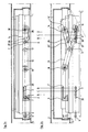
- the window shown in FIG. 1 comprises a sash frame 1 of the rebate type, articulated on a dorman frame 2.
- the cremone bolt 24 is connected by means of rods 20 to lugs 7, 8, 9, 10 secured to the rods 20 and positioned opposite the keepers 3, 4, 5 and 6, inside which they can move along the grooves, not shown, comprising widenings whose configuration and positioning allow the corresponding lug to come out of the keeper as a function of the position of the cremone bolt 24 and therefore of the chosen opening mode.
- the pins 7, 8, 9 and 10 can occupy four positions A, B, C, D, position A corresponding to the locking of the window and positions B, C, D to three possible opening modes, which will be described in detail below.
- the cremone bolt 24 connected to the lugs 7, 8, 9 and 10 by the rods 20 is also connected by this set of rods 20 to two lugs 11 and 12 secured respectively to the upper cross member and the lower cross member of the leaf 1 and also each secured to a set of articulated rods 13, 14, respectively 15, 16 actuating the movement of the leaf 1.
- the link 13 of the upper crosspiece connects the frame 2 to the door 1, being secured by one of its ends to a pivot 18 secured to the frame 2 and by the other end to a pivot 19 secured to the door 1 , while the link 14 connects the link 13 to the dorman 2 via a pivot 17 which fixes it to the link 13 at one of its ends and a pivot 19 ′ which fixes it to the frame 2 to its other end.
- the link 15 of the lower cross member connects the frame 2 to the door 1, being secured by one of its ends to a pivot 23 secured to the door 1, while the link 16 connects the link 15 to the frame 2 by means of a part of a pivot 21 which fixes it to the link 15 at one of its ends and a pivot 23 ′ which fixes it to the frame 2 at its other end.
- the pivot 23 as well as the lug 8 advantageously have a semi-spherical lower end to facilitate the tilting of the opening while ensuring the solidity of the support.
- FIGS. 2a and 2b clearly show the different possible positions of the links 13 and 14 of the upper crossmember, and the correlative path of the lug 11 in the different housings or grooves formed respectively in the opening 1, the link 13 and the connecting rod 14, as well as the corresponding movement of the lug 7 in the housing 3 ′ formed in the keeper 3 and on the other hand in the groove 28 formed in the leaf 1.
- FIGS. 3a and 3b clearly show the different possible positions of the links 15 and 16 of the bottom cross member, and the correlative path of the lug 12 in the different housings or grooves formed respectively in the leaf 1, the link 15, as well as the corresponding movement of the lug 8 in the housing formed in the keeper 4 of the frame 2.
- the opening 1 is seen in the closed position (shown in dotted lines), the set of connecting rods 15 and 16 "closed", that is to say the connecting rod 15 completely covering the connecting rod 16, the pivots 21 , 22 and 23 aligned, the lugs 8 and 12 in position A, the lug 8 being trapped in the housing 4 ′ of the keeper 4 of the frame 2 and the lug 12 being housed at one end of the groove 29 formed in the link 15 and at the corresponding end of a groove 30, formed in a plate secured to the opening 1.
- FIGS. 1, 2a and 3a which show the window according to the invention in the locked position
- the two sets of upper and lower connecting rods are closed and all the pins are in position A
- the lugs 7, 8, 9 and 10 being trapped in the keepers 3, 4, 5 and 6 while the lug 11 is blocked at one end of the groove 26 of the link 13, at the corresponding end of the groove 27 of the opening 1 and in the locking notch 25 ′ of the link 14, the lug 12 being on its side positioned at one end of the groove 29 of the link 15 and at the corresponding end of the groove 30 of the opening 1.
- the lugs 7, 8, 9 and 10 are then released from the keepers 3, 4, 5 and 6 while the lug 11 moves in a segment of the groove 26 then parallel to the top cross member, and the lug 12 comes position at the end of a segment (CD) of the groove 29 which comes to be placed parallel to the lower cross member of the frame 2. It follows that the leaf 1 is disengaged from the frame 2, the frame of the leaf 1 coming locate in a plane parallel to that of the frame 2.
- This "ventilation” position allows ventilation more complete and more efficient than the "bellows” opening because air circulates all around the opening frame.
- This ventilation position offers in addition the appreciable advantage of a safety vis-à-vis children, unlike the "French” opening which one is obliged to resort to with the swinging windows known when one wants more complete ventilation than that offered by the "bellows” opening.
- the four positions A, B, C, D of all the lugs 7, 8, 9, 10, 11 and 12 correspond to four positions of the cremone bolt easily identifiable thanks to slight blockings which it suffices to force to move from one position to another.
- the configuration of the multidirectional grooves formed in the rods 13 and 15 is determined as a function of the opening parameters, namely on the one hand the distance of movement of all the pins from position A to position B and on the other hand the greater or lesser distance from the sash to the frame in the "ventilation" opening, a distance which determines the length of the segment of each of the grooves 26 and 29 located between the two positions B and C. All of these parameters can be easily determined.
- the link 15 is advantageously a metal piece of large section whose all functions are allowed by precise machining of its pivot axes, as well as by milling the groove 29.
- the pivoting of the opening 1 in the French opening is also advantageously facilitated by using as pivot 23 a ball axis support mounted on a crimped ball joint.
- the opening and sleeping frames of the tilt-and-turn window according to the invention can be made of any material suitable for this type of device, such as wood, metal, or plastic, preferably PVC.
Landscapes
- Engineering & Computer Science (AREA)
- Mechanical Engineering (AREA)
- Specific Sealing Or Ventilating Devices For Doors And Windows (AREA)
- Window Of Vehicle (AREA)
- Wing Frames And Configurations (AREA)
- Air-Conditioning For Vehicles (AREA)
- Liquid Crystal Substances (AREA)
Claims (6)
- Drehkippfenster mit neben den beiden Öffnungsarten des Kippens und Schwenkens einer dritten, "Ventilation" genannten Öffnungsart, dessen Beschlag ein einziges Steuerorgan mit vier Positionen umfaßt, dadurch gekennzeichnet, daß der Fensterflügel (1) sich vollständig in die feststehende Fensterzarge (2) mit bündiger Ausrichtung des Flügelrahmens und der Fensterzarge einschmiegt, ohne sichtbare Fensterbänder, daß die "Ventilation" genannte Öffnungsart einer Verlagerung des Flügels (1) nach dem Ausrücken in einer parallel zu der Ebene der Zarge (2) verlaufenden Ebene entspricht, und daß das Steuerorgan (24) mit Hilfe von Gestängen (20) mit zwei Sätzen von zwei angelenkten Schwingarmen verbunden ist, von denen ein Satz (13, 14) an den oberen Querriegeln der Zarge (2) und des Flügels (1) und der andere (15, 16) an den unteren Querriegeln der Zarge (2) und des Flügels (1) befestigt ist, wobei die beiden Sätze von Schwingarmen sich jeweils aus einem Schwingarm (13) bzw. (15), der die Zarge (2) mit dem Flügel (1) mit Hilfe zweier Zapfen (18 und 19) bzw. (22 und 23) verbindet, und einem Schwingarm (14) bzw. (16) zusammensetzen, der den Schwingarm (13) bzw. (15) mit der Zarge (2) mit Hilfe von Zapfen (17 und 19') bzw. (21 und 23') verbindet, und die Schwingarme (13 und 15) jeweils eine in mehreren Richtungen verlaufende Nut (26) bzw. (29) enthalten, in deren Innerem sich ein Zuhaltungshaken (11) bzw. (12) verlagern kann, der über die Gestänge (20) mit dem Steuerorgan (24) verbunden ist und sich ebenfalls in einer Nut (27) bzw. (31) verlagern kann, die in einer mit dem Flügel (1) verbundenen Platte ausgespart ist, wobei der Zuhaltungshaken (11) bzw. (12) als Funktion der vier Positionen des Steuerorgans (24) vier Positionen (A, B, C, D) einnehmen kann, die der Verriegelung des Flügels (1) bzw. den drei möglichen oben genannten Öffnungsarten entsprechen.
- Drehkippfenster nach Anspruch 1, dadurch gekennzeichnet, daß es zuhaltungshaken (7, 8, 9, 10) aufweist, die mit den Gestängen (20) verbunden und in der Fensterzarge (2) angeordneten Schließkappen (3, 4, 5, 6) gegenüber positioniert sind, wobei die Schließkappen (3) und (4) auf dem oberen bzw. unteren Querbalken der Fensterzarge (2) und die Schließkappen (5) und (6) auf dem Höhenträger der Fensterzarge (2) angeordnet sind, der dem das Steuerorgan (24) tragenden Höhenschenkel des Flügels (1) gegenüberliegt, und wobei die zuhaltungshaken (7, 8, 9, 10) sich in den Schließkappen (3, 4, 5, 6) im Innern der Aufnahmen verlagern können, die in der Lage sind, sie gefangenzuhalten oder sie freizulassen, je nach der gewünschten Öffnungsart und der zugeordneten Position des Steuerorgans (24).
- Drehkippfenster nach Anspruch 1 oder Anspruch 2, dadurch gekennzeichnet, daß in der Verriegelungsposition (A) die Zuhaltungshaken (7, 8, 9, 10) in den Aufnahmen der Schließkappen (3, 4, 5, 6) blockiert sind, der mit dem oberen Satz von Schwingarmen verbundene zuhaltungshaken (11) in einem Blockierungsausschnitt (25'), der in der in dem Schwingarm (14) ausgesparten Öffnung (25) ausgebildet ist, und gleichzeitig an einem Ende der in dem Schwingarm (13) ausgesparten Nut (26) und an dem entsprechenden Ende der in einer mit dem Flügel (1) verbundenen Platte aufgesparten Nut (27), wobei der mit dem unteren Satz von Schwingarmen verbundene zuhaltungshaken (12) gleichzeitig in einem Ende der in dem Schwingarm (15) ausgesparten Nut (29) und an dem entsprechenden Ende einer in einer mit dem Flügel (1) verbundenen Platte ausgesparten Nut (30) blockiert ist.
- Drehkippfenster nach Anspruch 1 oder Anspruch 2, dadurch gekennzeichnet, daß in der Kippöffnungsposition (B) der mit den Gestängen (20) an dem oberen Querbalken des Flügels (1) verbundene zuhaltungshaken (7) und die mit den Gestängen (20) längs des Höhenschenkels des Flügels (1), der das Steuerorgan (24) trägt, verbundenen Zuhaltungshaken (9, 10) aus den in den Schließkappen (3, 5 und 6) angeordneten Aufnahmen befreit sind, daß der mit dem oberen Satz von Schwingarmen (13, 14) verbundene Zuhaltungshaken (11) seinerseits aus den verschiedenen in der Zarge (2) und dem Schwingarm (14) angebrachten Aufnahmen freigesetzt wird und sich in der Position (B) in der Vielrichtungsnut (26) des Schwingarms (13) positioniert befindet, was das Verschwenken des Flügels (1) um die von den Zuhaltungshaken (8) und (12), die beide in den in der Schließkappe (4) der Zarge (2) ausgebildeten Aufnahmen und gleichzeitig in der in dem Schwingarm (15) ausgebildeten Nut (29) und in der in einer mit dem Flügel (1) verbundenen Platte ausgebildeten Nut (30) blockiert sind, gebildete Achse ermöglicht.
- Drehkippfenster nach Anspruch 1 oder Anspruch 2, dadurch gekennzeichnet, daß in der "Ventilations"-Position (C) die Zuhaltungshaken (7, 8, 9, 10) aus den Schließkappen (3, 4, 5, 6) befreit sind, während der zuhaltungshaken (11) sich in einem Segment der Nut (26) verlagert, die jetzt parallel zu dem oberen Querriegel der Zarge (2) ist, und der Zuhaltungshaken (12) sich am Ende eines Segments der Nut (29) positioniert, die sich parallel zu dem unteren Querträger der Zarge (2) anordnet, wobei die Gesamtheit dieser Verlagerungen in einem Ausrücken des Flügels (1) aus der Zarge (2) resultiert und der Rahmen des Flügels (1) sich in einer Ebene anordnet, die parallel zu der Ebene der Zarge (2) ist.
- Drehkippfenster nach Anspruch 1 oder Anspruch 2, dadurch gekennzeichnet, daß in der Aufschwenk-Öffnungsstellung (D) die Zuhaltungshaken (7, 8, 9, 10) aus den Schließkappen (3, 4, 5, 6) befreit sind, während die Zuhaltungshaken (11) und (12) sich in den Nuten (26) und (29) zunächst parallel zu den Querträgern der Zarge (2) verlagern, dann in einem Kreisbogen, der jede der Nuten (26) und (29) beendet, wobei der Flügel (1) um die Zapfen (19') und (23') schwenkt.
Priority Applications (1)
| Application Number | Priority Date | Filing Date | Title |
|---|---|---|---|
| AT88440058T ATE101230T1 (de) | 1988-02-29 | 1988-07-06 | Drehkippfenster mit drei oeffnungsmoeglichkeiten. |
Applications Claiming Priority (2)
| Application Number | Priority Date | Filing Date | Title |
|---|---|---|---|
| FR8802672 | 1988-02-29 | ||
| FR8802672A FR2627798B1 (fr) | 1988-02-29 | 1988-02-29 | Fenetre oscillobattante a trois modes d'ouverture |
Publications (2)
| Publication Number | Publication Date |
|---|---|
| EP0330794A1 EP0330794A1 (de) | 1989-09-06 |
| EP0330794B1 true EP0330794B1 (de) | 1994-02-02 |
Family
ID=9363858
Family Applications (1)
| Application Number | Title | Priority Date | Filing Date |
|---|---|---|---|
| EP88440058A Expired - Lifetime EP0330794B1 (de) | 1988-02-29 | 1988-07-06 | Drehkippfenster mit drei Öffnungsmöglichkeiten |
Country Status (5)
| Country | Link |
|---|---|
| EP (1) | EP0330794B1 (de) |
| AT (1) | ATE101230T1 (de) |
| DE (1) | DE3887677T2 (de) |
| ES (1) | ES2050164T3 (de) |
| FR (1) | FR2627798B1 (de) |
Families Citing this family (5)
| Publication number | Priority date | Publication date | Assignee | Title |
|---|---|---|---|---|
| DE4417842A1 (de) * | 1994-05-20 | 1995-11-23 | Winkhaus Fa August | Teilautomatisch anschlagbares Beschlagssystem für Fenster, Türen oder dergleichen |
| DE10254537A1 (de) * | 2002-11-21 | 2004-06-03 | Aug. Winkhaus Gmbh & Co. Kg | Fenster oder Tür |
| DE102007017453C5 (de) † | 2007-04-02 | 2013-07-04 | Roto Frank Ag | Drehöffnungsbegrenzungsvorrichtung für einen Flügel eines Fensters oder dergleichen |
| CN103883184B (zh) * | 2014-04-01 | 2017-12-05 | 浙江力兴五金有限公司 | 推拉限位器 |
| IT201800002170A1 (it) * | 2018-01-30 | 2019-07-30 | Capoferri Serramenti S P A | Ferramenta per finestra |
Family Cites Families (6)
| Publication number | Priority date | Publication date | Assignee | Title |
|---|---|---|---|---|
| DE1124390B (de) * | 1957-04-11 | 1962-02-22 | Koller Metallbau Ag | Beschlag fuer parallel zuruecksetzbare sowie wahlweise kipp- oder schwenkbare Fluegel von Fenstern, Tueren od. dgl. |
| AT304842B (de) * | 1965-08-12 | 1973-01-25 | Gretsch Unitas Gmbh | Ausstell- und Verriegelungsvorrichtung für Fenster |
| DE1559787A1 (de) * | 1965-11-25 | 1970-02-19 | Weber Geb Winiarski | Ausstellvorrichtung fuer einen um eine waagerechte Achse kippbaren oder um eine lotrechte Achse schwenkbaren Oberlichtfluegel |
| AT366757B (de) * | 1980-06-06 | 1982-05-10 | Lapp Finze Ag | Abhebebeschlag fuer fenster, tueren od. dgl. |
| FR2510649A1 (fr) * | 1981-08-03 | 1983-02-04 | Siegenia Frank Kg | Dispositif d'aeration-ventilation par fente pour fenetres et pour portes a ouverture a la fois de type classique et de type a soufflet ou pour autres elements du meme genre |
| DE3442364C1 (de) * | 1984-11-20 | 1991-01-24 | Hautau Gmbh W | Verdeckt im Falz angeordneter Beschlag für Kipp-Schwenkflügelfenster oder -türen |
-
1988
- 1988-02-29 FR FR8802672A patent/FR2627798B1/fr not_active Expired - Fee Related
- 1988-07-06 ES ES88440058T patent/ES2050164T3/es not_active Expired - Lifetime
- 1988-07-06 AT AT88440058T patent/ATE101230T1/de not_active IP Right Cessation
- 1988-07-06 EP EP88440058A patent/EP0330794B1/de not_active Expired - Lifetime
- 1988-07-06 DE DE3887677T patent/DE3887677T2/de not_active Expired - Fee Related
Also Published As
| Publication number | Publication date |
|---|---|
| ES2050164T3 (es) | 1994-05-16 |
| EP0330794A1 (de) | 1989-09-06 |
| FR2627798B1 (fr) | 1990-08-17 |
| DE3887677D1 (de) | 1994-03-17 |
| FR2627798A1 (fr) | 1989-09-01 |
| ATE101230T1 (de) | 1994-02-15 |
| DE3887677T2 (de) | 1994-07-28 |
Similar Documents
| Publication | Publication Date | Title |
|---|---|---|
| FR2574718A1 (fr) | Systeme de lunette arriere escamotable pour vehicule | |
| EP0014147A1 (de) | Tür mit reduziertem Schwenkausschlag | |
| EP0219589B1 (de) | Falttür | |
| EP0330794A1 (de) | Drehkippfenster mit drei Öffnungsmöglichkeiten | |
| FR2489876A1 (fr) | Ferrure pour le vantail coulissant des fenetres, portes ou analogues | |
| EP0044799B1 (de) | Beschlag für Schiebefenster, Schiebetüren oder dgl. | |
| EP1140535A1 (de) | Sicherheitsvorrichtung mit glasöffnung mit beweglichem verschluss | |
| FR2538846A1 (fr) | Dispositif de securite pour porte evitant l'ecrasement des doigts entre dormant et ouvrant | |
| FR2662344A1 (fr) | Boitier, notamment boite aux lettres, comportant des moyens de verrouillage simplifies. | |
| EP0012677B1 (de) | Gefälle regulierende, einstellbare Türangel | |
| FR2577976A1 (fr) | Element d'ouverture mobile ouvrant dans les deux sens | |
| FR2639992A2 (fr) | Fenetre oscillobattante a trois modes d'ouverture et a deux vantaux | |
| EP1524399A1 (de) | Schutzgitter | |
| EP0330795A1 (de) | Drehkippfenster | |
| EP1563150A2 (de) | Griff, insbesondere für kraftfahrzeugtüren | |
| EP1134341B1 (de) | Gelenktürsystem für Fahrzeuge, Behälter und dergleichen | |
| FR2634510A1 (fr) | Pivot pour fenetre basculante ou oscillante de toiture | |
| FR2629856A1 (de) | ||
| FR2929317A1 (fr) | Porte de garage et ensemble comportant une telle porte | |
| FR2601063A1 (fr) | Coffre principal destine a etre integre dans une fermeture anti-panique du type a barre d'enfoncement dite " push-bar ". | |
| FR2683579A1 (fr) | Agencement de verrouillage d'un organe mobile de fermeture d'une ouverture, telle qu'une porte. | |
| FR2553347A1 (fr) | Porte d'acces pour vehicule de transport en commun | |
| FR2766513A1 (fr) | Dispositif d'articulation cachee pour chassis a frappe de porte, fenetre ou analogue | |
| FR2511723A1 (fr) | Ensemble palier-penture pour porte de conteneurs ou de vehicules | |
| FR2729177A1 (fr) | Dispositif de securite a la fermeture pour fenetres, portes et portes-fenetres coulissantes |
Legal Events
| Date | Code | Title | Description |
|---|---|---|---|
| PUAI | Public reference made under article 153(3) epc to a published international application that has entered the european phase |
Free format text: ORIGINAL CODE: 0009012 |
|
| AK | Designated contracting states |
Kind code of ref document: A1 Designated state(s): AT BE CH DE ES GB GR IT LI LU NL SE |
|
| 17P | Request for examination filed |
Effective date: 19900502 |
|
| 17Q | First examination report despatched |
Effective date: 19920221 |
|
| GRAA | (expected) grant |
Free format text: ORIGINAL CODE: 0009210 |
|
| AK | Designated contracting states |
Kind code of ref document: B1 Designated state(s): AT BE CH DE ES GB GR IT LI LU NL SE |
|
| REF | Corresponds to: |
Ref document number: 101230 Country of ref document: AT Date of ref document: 19940215 Kind code of ref document: T |
|
| REF | Corresponds to: |
Ref document number: 3887677 Country of ref document: DE Date of ref document: 19940317 |
|
| ITF | It: translation for a ep patent filed | ||
| REG | Reference to a national code |
Ref country code: ES Ref legal event code: FG2A Ref document number: 2050164 Country of ref document: ES Kind code of ref document: T3 |
|
| GBT | Gb: translation of ep patent filed (gb section 77(6)(a)/1977) |
Effective date: 19940421 |
|
| REG | Reference to a national code |
Ref country code: GR Ref legal event code: FG4A Free format text: 3011633 |
|
| EPTA | Lu: last paid annual fee | ||
| PLBI | Opposition filed |
Free format text: ORIGINAL CODE: 0009260 |
|
| 26 | Opposition filed |
Opponent name: SIEGENIA-FRANK KG Effective date: 19941019 |
|
| EAL | Se: european patent in force in sweden |
Ref document number: 88440058.1 |
|
| NLR1 | Nl: opposition has been filed with the epo |
Opponent name: SIEGENIA-FRANK KG |
|
| PLBN | Opposition rejected |
Free format text: ORIGINAL CODE: 0009273 |
|
| STAA | Information on the status of an ep patent application or granted ep patent |
Free format text: STATUS: OPPOSITION REJECTED |
|
| 27O | Opposition rejected |
Effective date: 19951009 |
|
| NLR2 | Nl: decision of opposition | ||
| PGFP | Annual fee paid to national office [announced via postgrant information from national office to epo] |
Ref country code: GB Payment date: 19980706 Year of fee payment: 11 |
|
| PGFP | Annual fee paid to national office [announced via postgrant information from national office to epo] |
Ref country code: AT Payment date: 19980713 Year of fee payment: 11 |
|
| PGFP | Annual fee paid to national office [announced via postgrant information from national office to epo] |
Ref country code: GR Payment date: 19980714 Year of fee payment: 11 |
|
| PGFP | Annual fee paid to national office [announced via postgrant information from national office to epo] |
Ref country code: ES Payment date: 19980716 Year of fee payment: 11 |
|
| PGFP | Annual fee paid to national office [announced via postgrant information from national office to epo] |
Ref country code: DE Payment date: 19980721 Year of fee payment: 11 |
|
| PGFP | Annual fee paid to national office [announced via postgrant information from national office to epo] |
Ref country code: SE Payment date: 19980727 Year of fee payment: 11 |
|
| PGFP | Annual fee paid to national office [announced via postgrant information from national office to epo] |
Ref country code: LU Payment date: 19980729 Year of fee payment: 11 |
|
| PGFP | Annual fee paid to national office [announced via postgrant information from national office to epo] |
Ref country code: NL Payment date: 19980731 Year of fee payment: 11 |
|
| PGFP | Annual fee paid to national office [announced via postgrant information from national office to epo] |
Ref country code: BE Payment date: 19980803 Year of fee payment: 11 |
|
| PGFP | Annual fee paid to national office [announced via postgrant information from national office to epo] |
Ref country code: CH Payment date: 19981023 Year of fee payment: 11 |
|
| PG25 | Lapsed in a contracting state [announced via postgrant information from national office to epo] |
Ref country code: LU Free format text: LAPSE BECAUSE OF NON-PAYMENT OF DUE FEES Effective date: 19990706 Ref country code: GB Free format text: LAPSE BECAUSE OF NON-PAYMENT OF DUE FEES Effective date: 19990706 Ref country code: AT Free format text: LAPSE BECAUSE OF NON-PAYMENT OF DUE FEES Effective date: 19990706 |
|
| PG25 | Lapsed in a contracting state [announced via postgrant information from national office to epo] |
Ref country code: SE Free format text: THE PATENT HAS BEEN ANNULLED BY A DECISION OF A NATIONAL AUTHORITY Effective date: 19990707 Ref country code: ES Free format text: LAPSE BECAUSE OF NON-PAYMENT OF DUE FEES Effective date: 19990707 |
|
| PG25 | Lapsed in a contracting state [announced via postgrant information from national office to epo] |
Ref country code: LI Free format text: LAPSE BECAUSE OF NON-PAYMENT OF DUE FEES Effective date: 19990731 Ref country code: GR Free format text: LAPSE BECAUSE OF NON-PAYMENT OF DUE FEES Effective date: 19990731 Ref country code: DE Free format text: LAPSE BECAUSE OF NON-PAYMENT OF DUE FEES Effective date: 19990731 Ref country code: CH Free format text: LAPSE BECAUSE OF NON-PAYMENT OF DUE FEES Effective date: 19990731 Ref country code: BE Free format text: LAPSE BECAUSE OF NON-PAYMENT OF DUE FEES Effective date: 19990731 |
|
| BERE | Be: lapsed |
Owner name: SOC. FINANCIERE YVES JUDEL Effective date: 19990731 |
|
| PG25 | Lapsed in a contracting state [announced via postgrant information from national office to epo] |
Ref country code: NL Free format text: LAPSE BECAUSE OF NON-PAYMENT OF DUE FEES Effective date: 20000201 |
|
| GBPC | Gb: european patent ceased through non-payment of renewal fee |
Effective date: 19990706 |
|
| REG | Reference to a national code |
Ref country code: CH Ref legal event code: PL |
|
| EUG | Se: european patent has lapsed |
Ref document number: 88440058.1 |
|
| NLV4 | Nl: lapsed or anulled due to non-payment of the annual fee |
Effective date: 20000201 |
|
| REG | Reference to a national code |
Ref country code: ES Ref legal event code: FD2A Effective date: 20000810 |
|
| PG25 | Lapsed in a contracting state [announced via postgrant information from national office to epo] |
Ref country code: IT Free format text: LAPSE BECAUSE OF NON-PAYMENT OF DUE FEES;WARNING: LAPSES OF ITALIAN PATENTS WITH EFFECTIVE DATE BEFORE 2007 MAY HAVE OCCURRED AT ANY TIME BEFORE 2007. THE CORRECT EFFECTIVE DATE MAY BE DIFFERENT FROM THE ONE RECORDED. Effective date: 20050706 |