EP0330942A1 - Anzeige für Messinstrument - Google Patents
Anzeige für Messinstrument Download PDFInfo
- Publication number
- EP0330942A1 EP0330942A1 EP89102846A EP89102846A EP0330942A1 EP 0330942 A1 EP0330942 A1 EP 0330942A1 EP 89102846 A EP89102846 A EP 89102846A EP 89102846 A EP89102846 A EP 89102846A EP 0330942 A1 EP0330942 A1 EP 0330942A1
- Authority
- EP
- European Patent Office
- Prior art keywords
- cell
- display
- display device
- control circuit
- motor
- Prior art date
- Legal status (The legal status is an assumption and is not a legal conclusion. Google has not performed a legal analysis and makes no representation as to the accuracy of the status listed.)
- Granted
Links
- 239000004973 liquid crystal related substance Substances 0.000 claims abstract description 14
- 230000004913 activation Effects 0.000 claims abstract description 7
- 230000004044 response Effects 0.000 claims abstract description 6
- 210000004027 cell Anatomy 0.000 claims description 90
- 239000003086 colorant Substances 0.000 claims description 5
- 210000002858 crystal cell Anatomy 0.000 claims description 4
- 238000000034 method Methods 0.000 claims description 3
- 230000008569 process Effects 0.000 claims description 2
- 238000005259 measurement Methods 0.000 description 11
- PEDCQBHIVMGVHV-UHFFFAOYSA-N Glycerine Chemical compound OCC(O)CO PEDCQBHIVMGVHV-UHFFFAOYSA-N 0.000 description 10
- 239000000203 mixture Substances 0.000 description 8
- 230000005684 electric field Effects 0.000 description 6
- 230000008901 benefit Effects 0.000 description 4
- 230000010287 polarization Effects 0.000 description 4
- 239000004988 Nematic liquid crystal Substances 0.000 description 3
- 240000008042 Zea mays Species 0.000 description 2
- 238000010521 absorption reaction Methods 0.000 description 2
- 230000002457 bidirectional effect Effects 0.000 description 2
- 239000004020 conductor Substances 0.000 description 2
- 239000000446 fuel Substances 0.000 description 2
- 239000011521 glass Substances 0.000 description 2
- 238000009434 installation Methods 0.000 description 2
- 230000000737 periodic effect Effects 0.000 description 2
- XLYOFNOQVPJJNP-UHFFFAOYSA-N water Substances O XLYOFNOQVPJJNP-UHFFFAOYSA-N 0.000 description 2
- UWCWUCKPEYNDNV-LBPRGKRZSA-N 2,6-dimethyl-n-[[(2s)-pyrrolidin-2-yl]methyl]aniline Chemical compound CC1=CC=CC(C)=C1NC[C@H]1NCCC1 UWCWUCKPEYNDNV-LBPRGKRZSA-N 0.000 description 1
- 239000004986 Cholesteric liquid crystals (ChLC) Substances 0.000 description 1
- 241000397921 Turbellaria Species 0.000 description 1
- 230000003213 activating effect Effects 0.000 description 1
- 238000013459 approach Methods 0.000 description 1
- 230000005540 biological transmission Effects 0.000 description 1
- 230000008859 change Effects 0.000 description 1
- 239000003795 chemical substances by application Substances 0.000 description 1
- 230000000295 complement effect Effects 0.000 description 1
- 150000001875 compounds Chemical class 0.000 description 1
- 239000013078 crystal Substances 0.000 description 1
- 238000006073 displacement reaction Methods 0.000 description 1
- APFVFJFRJDLVQX-UHFFFAOYSA-N indium atom Chemical compound [In] APFVFJFRJDLVQX-UHFFFAOYSA-N 0.000 description 1
- 229910003437 indium oxide Inorganic materials 0.000 description 1
- 230000006698 induction Effects 0.000 description 1
- 230000005415 magnetization Effects 0.000 description 1
- 239000000463 material Substances 0.000 description 1
- 239000011159 matrix material Substances 0.000 description 1
- 230000004048 modification Effects 0.000 description 1
- 238000012986 modification Methods 0.000 description 1
- 238000012544 monitoring process Methods 0.000 description 1
- 230000003287 optical effect Effects 0.000 description 1
- 210000000056 organ Anatomy 0.000 description 1
- 239000010453 quartz Substances 0.000 description 1
- 238000000926 separation method Methods 0.000 description 1
- 238000007493 shaping process Methods 0.000 description 1
- 230000035939 shock Effects 0.000 description 1
- VYPSYNLAJGMNEJ-UHFFFAOYSA-N silicon dioxide Inorganic materials O=[Si]=O VYPSYNLAJGMNEJ-UHFFFAOYSA-N 0.000 description 1
- 239000000126 substance Substances 0.000 description 1
- XOLBLPGZBRYERU-UHFFFAOYSA-N tin dioxide Chemical compound O=[Sn]=O XOLBLPGZBRYERU-UHFFFAOYSA-N 0.000 description 1
- 229910001887 tin oxide Inorganic materials 0.000 description 1
- 230000001131 transforming effect Effects 0.000 description 1
Images


Classifications
-
- G—PHYSICS
- G01—MEASURING; TESTING
- G01R—MEASURING ELECTRIC VARIABLES; MEASURING MAGNETIC VARIABLES
- G01R1/00—Details of instruments or arrangements of the types included in groups G01R5/00 - G01R13/00 and G01R31/00
- G01R1/02—General constructional details
- G01R1/08—Pointers; Scales; Scale illumination
-
- G—PHYSICS
- G01—MEASURING; TESTING
- G01D—MEASURING NOT SPECIALLY ADAPTED FOR A SPECIFIC VARIABLE; ARRANGEMENTS FOR MEASURING TWO OR MORE VARIABLES NOT COVERED IN A SINGLE OTHER SUBCLASS; TARIFF METERING APPARATUS; MEASURING OR TESTING NOT OTHERWISE PROVIDED FOR
- G01D7/00—Indicating measured values
- G01D7/002—Indicating measured values giving both analog and numerical indication
Definitions
- the present invention relates to display devices for measuring instruments.
- analog display devices are less precise than digital display devices, but they have an advantage over them.
- Analog display devices allow you to have a good overview and quickly see that the installation is working properly or that there is an anomaly somewhere.
- an error specific to the galvanometer is added to the measurement error which may vary depending on the value of the quantity measured.
- galvanometers are often sensitive to shock and vibration.
- the object of the invention is precisely to provide a display device which makes it possible to do all of this, separately or in combination, and not only for vehicles but also for any other application for which the same things would be desirable.
- a device for displaying the value of at least one quantity which also comprises a movable indicator member driven by a stepping motor, a first control circuit which responds at least indirectly to input information which represents the quantity in question by applying driving pulses to the motor to bring the indicator member to a position which corresponds to the value of the quantity, and means for present a tracking system which cooperates with the indicating member to indicate at least in which field this value lies, these means comprise an electro-optical display cell for displaying the tracking system in response to control signals, and the fact that this display device also comprises a second control circuit for applying these control signals to the cell, in response to an activation signal.
- electro-optical display cell designates here a cell which comprises at least two insulating plates between which is trapped a layer of material capable of responding to the presence of an electric field by a modification of its optical behavior and electrodes carried by these plates, which create the field in question.
- each of these ways of displaying the tracking system has the advantages and one may have to choose one over the other, depending on the application to which the display device is destined.
- the cell when it is useful or necessary, can be designed to be able to display at least two tracking systems and the second control circuit can then receive, in addition, a selection signal in order to be able to apply to the cell different control signals to cause it to selectively display either of the two systems.
- the two tracking systems can correspond to different value domains of the same magnitude and the device can also comprise means which also receive the selection signal and which process the input information before sending it to the first control circuit, so that the number of driving pulses applied to the motor is adapted to the tracking system displayed by the cell.
- the two tracking systems are provided to indicate the values of different quantities, that these values are represented by respective input information received by the display device and that the latter also comprises means which receive the selection signal and which select the input information which corresponds to the tracking system displayed by the cell to apply it to the first control circuit.
- the cell is designed to be able to display the two tracking systems, which can be, for example, two graduated scales, one in place of the other.
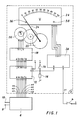
- the voltmeter which is shown schematically in Figure 1 is intended to measure voltages between 0 and 100 V.
- Its display device 2 is designed to make it possible to read the value of a voltage on graduated scales from 0 to 100 V and from 0 to 30 V.
- This device has a first input e1 connected to a connection switch 4 which makes it possible to energize all of the circuits of the voltmeter by connecting them to the positive terminal of a DC supply voltage source, not shown.
- the signal produced by the closing of this switch 4 constitutes here the activation signal of which we have spoken.
- the device 2 also has seven other inputs e2 to e8 by which it can receive information of seven bits which is supplied by a measurement circuit 6 when the voltmeter is connected and that a voltage is applied between the input terminals 8 and 10 thereof, this information being understood to be representative of the value of said voltage.
- the seven inputs e2 to e8 are connected to seven corresponding inputs a to g of a two-bit multiplier circuit 12 which also has two other inputs h and i to determine its multiplication rate and seven outputs j to p.
- the input h is connected to the common terminal of a switch 14, the other terminal of which is connected to the positive terminal of the supply voltage source of the voltmeter, and of a resistor 16, the other terminal of which is connected to ground.
- the input is connected directly to the positive terminal of the source.
- the multiplier circuit is content to transmit the information it receives on its inputs a to g at its outputs j to p.
- the seven outputs of the multiplier circuit 12 are in turn connected to seven corresponding inputs a to g of the control circuit 18 of a bidirectional stepper motor 20 which is coupled to a needle 24, via a gear train 22 , so that it can rotate around an axis, in both directions and within limits which will be specified later.
- the display device 2 comprises a dial 26 which here consists entirely of a liquid crystal display cell, which makes it possible to selectively display, in the same place, the two scales graduated from 0 to 100 V and from 0 at 30 V, and a control circuit 28 for this cell, which has two inputs a and b connected respectively to the input e1 of the device and to the common terminal of the switch 14 and of the resistor 16 and four outputs c to f.
- the motor 20 can for example be that which is the subject of US Pat. No. 4,361,790.
- This motor comprises a rotor constituted by a bipolar magnet with diametric magnetization, a stator with three polar parts which surround the rotor and two coils which must be powered by bipolar driving pulses to rotate the rotor in one direction or the other, in 180 ° steps.
- the two coils of such a motor are supplied simultaneously, which means that they must each be connected diagonally in a bridge of four power transistors. This explains the four conductors which connect the motor 20 to four outputs j to k of the control circuit 18 in FIG. 1.
- control circuit 18 will not be described here because it can form, with the multiplier circuit 12, the switch 14 and the resistor 16, the same circuit as that described in the aforementioned US Patent No. 4,314,146.
- cell 26 it can theoretically be of any type currently known. However, for a voltmeter like the one that is being described, it is preferable to use a cell operating by reflection, such as for example one of those which are represented schematically, in section, in FIGS. 2a and 2b.
- the cell which is represented in FIG. 2a is a positive contrast cell, that is to say a cell which makes it possible to display scales in dark on a light background and to which must obviously be associated a black needle 24 or dark color.
- This cell of FIG. 2a comprises a front plate 30 and a rear plate 32 transparent and joined together by a frame 34, so as to form a sealed enclosure in which is trapped a layer of nematic liquid crystal with positive dielectric anisotropy.
- the front plate 30 carries on its internal face a set of transparent electrodes 36, for example made of indium or tin oxide, the configuration of which corresponds to that of the scales, and an alignment layer not shown for orienting the molecules.
- transparent electrodes 36 for example made of indium or tin oxide, the configuration of which corresponds to that of the scales, and an alignment layer not shown for orienting the molecules.
- liquid crystal or mixture which are in its vicinity in a direction parallel to the plates and to the plane of the figure, this in the absence of an electric field.
- a transparent counter-electrode 38 which covers this plate at least throughout the display area, and an alignment layer also not shown to orient the molecules.
- liquid crystal which are close to it always in a direction parallel to the plates but perpendicular to the plane of the figure.
- the cell of FIG. 2a also comprises a first polarizer 40, which is fixed to the external face of the front plate 30 and whose polarization direction is parallel to the plates and to the plane of the figure, a second polarizer 42, fixed on the external face of the plate 32, the direction of polarization of which is perpendicular to that of the first polarizer, and a reflector-diffuser 44 fixed on the rear face of this second polarizer.
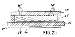
- the cell in FIG. 2b is another type of cell which also makes it possible to display light scales on a dark background.
- It includes a front plate 30 ′, a rear plate 32 ′, a frame 34 ′, a set of electrodes 36 ′ and a counter electrode 38 ′ which are identical to those of the cell of FIG. 2a and arranged in the same way.
- it also includes a reflector-diffuser 44 ′ placed at the rear of the plate 32 ′.
- This cell which is generally designated by the name of its inventor HEILMEIER is also well known and without the need to give explanations on its functioning it can be said that thanks to the presence of the pleochroic dye it makes it possible to display scales on a practically black background, which means that if you choose, as it should be, a white needle or a light color and preferably bright it detaches very well from this background. Naturally, if desired, we could also use, instead of the one indicated, a pleochroic dye which would absorb only part of the visible wavelengths to obtain a background not black but of dark color.
- the first example is a cell which is described in US Pat. No. 3,833,287 and which uses a mixture of nematic liquid crystal with positive dielectric anisotropy, pleochroic dye and cholesteric liquid crystal or chiral agent as well as layers planar alignment. This cell is negative contrast and requires no polarizer.
- the second example is a cell like that described in US Pat. No. 4,281,903 and which comprises a mixture of nematic liquid crystal with negative dielectric anisotropy, chiralic agent and pleochroic dye and homeotropic alignment layers on its plates which allow the molecules of the mixture to be oriented perpendicularly to the latter, in the absence of an electric field.
- This cell which also operates without a polarizer, has positive contrast.
- a cell which displays something dark on a light background has better contrast and greater luminance than a cell which displays the same thing in light on a dark background.
- the surface of a cell which constitutes the background on which the scale can appear is the surface furthest from the needle which reflects light likely to reach the eye of a person who looks at it.
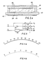
- FIG. 3 shows how all of the electrodes 36 of the cell of FIG. 2a or of the electrodes 36 ′ of the cell of FIG. 2b can be made to allow selectively displaying a graduated scale from 0 to 100 or a graduated scale from 0 to 30.
- This set includes 101 radial and equidistant segments s (1) to s (101) to display the graduations of the two scales, fourteen groups of segments S (1) to S (14) to display above the corresponding graduations the numbers of marking 0, 10, 20, 30, 40, 50, 60, 70, 80, 90 and 100 for the scale from 0 to 100 and the numbers 0, 5, 10, 20, 25 and 30 for the scale from 0 to 30 which, as we will see later, actually goes a little further, and three segments s ′ (16), s ′ (46) and s ′ (76) which allow the segments s (16) to be extended , s (46) and s (76) for the scale from 0 to 30.
- the eight segments of group S (2) which form the number 10 are connected to each other and to track P2. Likewise for the segments of the groups S (4) S (6) S (8) S (10) S (12) and S (14) which form the numbers 20, 40, 50, 70, 80 and 100.
- the five segments of group S (3) which form the number 5 and the extension segment s ′ (16) are linked together and to track P3 and the same is true for the segments of group S (7) which form the number 15 and the segment s ′ (46) and for those of group S (11) which form the number 25 and the segment s ′ (76).
- the segments of groups S (5), S (9) and S (13) allow the display of different registration numbers for the two scales.
- Group S (5) comprises a first digit with two vertical segments b and c and three horizontal segments a, d and g (see fig. 3a) to display the digit 1 or the digit 3 and a second digit of six segments to display the digit 0.
- the two vertical segments of the first digit and the six segments of the second are connected to each other and to track P1, via the segment s (31), while the three horizontal segments of the first digit are connected to track P2.
- Group S (9) includes a first digit with seven segments a to g, classic (see fig. 3b), to display the digits 2 and 6 and a second digit of six segments for the digit 0.
- the segments a, d, e and g of the first digit and those of the second digit are all linked together and to track P1 while the segments c and f of the first digit are connected to track P2 and its segment b to the track P3.
- Group S (13) includes a first digit of six segments a, b, c, d, f, g, (see fig. 3c) to display the digits 3 and 9 and a second digit of six segments for the digit 0.
- the segments a, b, c, d and g of the first digit and those of the second are linked together and to track P1 while the segment f of the first digit is connected to track P2.
- the cell displays the scale from 0 to 30 or more precisely from 0 to 33, which can be seen in FIG. 4b.
- the cell control circuit which can be seen in FIG. 5, includes an oscillator 46 which is connected to the input a so that it can be powered (see fig. 1).
- this oscillator produces periodic pulses of frequency between 30 and 60 Hz, for example 50 Hz, which are directly sent to the output c of the circuit which is connected to the counter electrode 38 or 38 ′ of the cell (see Figures 2a and 2b).
- These pulses are also applied to the input of an inverter 48 and to the first inputs of two gates OR EXCLUSIVE 50 and 52 whose outputs are connected respectively to the outputs d, e and f of the circuit which are themselves connected to the tracks P1, P2 and P3 of the cubicle (see fig. 3).
- the input b of the circuit is connected directly to a second input of the door 52 and by means of an inverter 54 to a second input of the door 50.
- the front plate of the cell 26 carries two stops 56 and 58 to limit the stroke of the needle 24.
- the position of the first, 56, these stops is important because it must force the needle to stop exactly opposite the 0 graduation of the two scales. That of the other stop 58 is less so. It should only allow the needle to reach the 100 graduation and there is no disadvantage that this needle can go a little beyond.
- the cell 26 instantly displays the scale from 0 to 100.
- the measurement circuit supplies the binary information 1000011 to the multiplier circuit 12 which is content to transmit it as it is to the control circuit 18 and the latter is then responsible for transforming this information into as many driving pulses as it takes to turn the motor 20 67 steps forward and to bring the needle 24 opposite the graduation 67 of the dial.
- the circuit 12 multiplies the binary information 0010101 which comes from the measurement circuit by three.
- control circuit 18 receives the information 0111111 and causes the motor to take 63 steps in forward motion so that the needle comes to be positioned opposite the graduation 21 of the scale.
- this switch 14 it should be noted that it could very well, in a variant, be replaced by a comparator which would compare the output information of the measurement circuit with the number binary corresponding to 30 and whose output signal would automatically select the multiplication rate of circuit 12 and the displayed scale according to the value of the measured voltage.
- the activation signal could be produced not by connection switch 4 but by the measurement circuit or other means, when a voltage is applied between the terminals 8 and 10 of the voltmeter .
- a voltmeter capable of displaying voltages on scales from 0 to 1, 10 and 100.
- the multiplication circuit would be eliminated and the selection switch 14 would be replaced by a three-position switch which would apply selection signals to the measurement circuit so that it provides the same binary information for the same number of hundredths of sees, tenths of volts and volts.
- the cell and its control circuit which would also receive the selection signals, they would be designed so that we always have the same graduations but with different identification numbers above them, for example 0, 0.1, 0.2 , ..., 1.0 for the 0 to 1 V scale, 0, 1.0, 2.0, ..., 10.0 for the 0 to 10 V scale and 0, 10, 20, ..., 100 for the from 0 to 100 V.
- a display device could also have been described to indicate voltage values on a linear scale, graduated for example from 0 to 100 V and resistance values on a non-linear scale graduated from 0 to 1000 ⁇ .
- a device of this kind could comprise two groups of inputs by which it would receive information representative of the two quantities and a selector controlled by a switch or automatically to select one or the other of this information and apply it to the motor control circuit. which would obviously be different from that of the display device in FIG. 1.
- FIG. 6 partially shows another example of a display device according to the invention, very different from those of which we have just spoken. It is a speedometer for cars, intended to be illuminated at night from the front and of which we can see on the figure in question only the dial 60 and the needle 62 which can be driven in rotation by a stepper motor and a cog placed behind the dial.
- the dial 60 comprises an opaque circular plate 64, pierced with a central hole for the passage of the axis of the needle and on which has been shown a scale in the form of a portion of a circle, graduated from 0 to 200.
- this plate 64 carries at the front a stop 66 for the setting of the needle 62 on the position 0 of the scale.
- This cell 74 is designed to be able to show ranges of different colors, the separations of which correspond to speed limits imposed by the highway code.
- first range 76 of blue color which goes from 0 to 60
- second range 78 of green color which goes from 60 to 100
- third range 80 of yellow color which goes from 100 to 130
- fourth range 82 of red color which goes from 130 to 200, since the limits for city, road and highway driving are 60, 100 and 130 km / h.
- the first consists in successively activating the ranges as the speed of the car increases, without deactivating the preceding range (s).
- the second is to activate only the range in which the speed of the car is located.
- This cell which is shown in section in FIG. 7, comprises a front plate 84 and a rear plate 86 made of glass, which respectively carry on their facing faces four adjacent electrodes 88, 90, 92 and 94, which correspond to the four areas to be displayed, and a single counter-electrode 96.
- the two plates 84 and 86, the facing faces of which are additionally covered with planar alignment layers, not shown, are joined together by a sintered glass frame 98 to form a sealed enclosure.
- liquid crystal with positive dielectric anisotropy mixed with a chiralic compound and a pleochroic dye which is chosen to make it possible to give the different non-activated areas the black or dark gray color which it is sought to obtain.
- the cell in FIG. 7 also includes four diffusing reflectors 100, 102, 104 and 106, of different colors, which are fixed to the external face of the rear plate 86 and which are located exactly opposite the four electrodes.
- the molecules of the mixture are parallel to the plates and have a helical structure of low pitch, so that practically all the incident light is absorbed. by the pleochroic dye molecules and that the areas then effectively have the desired black or dark gray color.
- the electronic part of a speedometer such as that of FIG. 6 may for example include a circuit for shaping the signal produced by an induction sensor which detects the speed of rotation of the output shaft of the gearbox and to transform this signal into binary information of several bits, a motor control circuit inspired by that of US Pat. No. 4,314,146, which receives this binary information, three comparators to which this information is also applied and a control circuit for the cell which is connected to the outputs of these three comparators and which receives an activation signal when the car is started.
- the cell control circuit can be very simple. In the first case that we have considered, where the speed ranges exceeded remain displayed, it may include only one oscillator, one inverter and three gates OR EXCLUSIVE.
- Linear stepper motors could also be used to drive indicator organs, and cells which would use electrochromic or electroluminescent substances as the active component.
- a display device may very well in certain cases receive information representative of the value of a quantity to be displayed in analog form and be responsible for the put it in digital form to be able to use it.
Landscapes
- Physics & Mathematics (AREA)
- General Physics & Mathematics (AREA)
- Indicating Measured Values (AREA)
- Instrument Panels (AREA)
- Devices For Indicating Variable Information By Combining Individual Elements (AREA)
Applications Claiming Priority (2)
| Application Number | Priority Date | Filing Date | Title |
|---|---|---|---|
| FR8802591 | 1988-02-29 | ||
| FR8802591A FR2627864A1 (fr) | 1988-02-29 | 1988-02-29 | Dispositif d'affichage pour instrument de mesure |
Publications (2)
| Publication Number | Publication Date |
|---|---|
| EP0330942A1 true EP0330942A1 (de) | 1989-09-06 |
| EP0330942B1 EP0330942B1 (de) | 1993-07-07 |
Family
ID=9363805
Family Applications (1)
| Application Number | Title | Priority Date | Filing Date |
|---|---|---|---|
| EP89102846A Expired - Lifetime EP0330942B1 (de) | 1988-02-29 | 1989-02-18 | Anzeige für Messinstrument |
Country Status (5)
| Country | Link |
|---|---|
| US (1) | US4968930A (de) |
| EP (1) | EP0330942B1 (de) |
| JP (1) | JPH01272919A (de) |
| DE (1) | DE68907421T2 (de) |
| FR (1) | FR2627864A1 (de) |
Cited By (3)
| Publication number | Priority date | Publication date | Assignee | Title |
|---|---|---|---|---|
| EP0447580A1 (de) * | 1988-11-05 | 1991-09-25 | Karl-Bernhard Nüchter | Messvorrichtung |
| EP0632276A1 (de) * | 1993-06-29 | 1995-01-04 | Societe D'applications Generales D'electricite Et De Mecanique Sagem | Verfahren zur Verwendung eines Anzeigeinstrumentes |
| DE19705452A1 (de) * | 1997-02-13 | 1998-08-20 | Bosch Gmbh Robert | Doppelskala für Kombi-Instrumente |
Families Citing this family (23)
| Publication number | Priority date | Publication date | Assignee | Title |
|---|---|---|---|---|
| GB2219683B (en) * | 1988-06-10 | 1992-03-18 | Megger Instr Ltd | Improvements in or relating to measuring instruments |
| GB2270567A (en) * | 1992-09-12 | 1994-03-16 | Ford Motor Co | Instrument panel gauge. |
| US5696704A (en) * | 1995-06-07 | 1997-12-09 | Vdo North America, Inc. | Non-linear scale instrument |
| US5869776A (en) * | 1997-02-26 | 1999-02-09 | Kuhlman Corporation | Method and apparatus for receiving and displaying digital data |
| US5920256A (en) * | 1997-04-08 | 1999-07-06 | Ut Automotive Dearborn, Inc. | Gauge with mechanical indicator and reconfigurable gauge display |
| DE19733650A1 (de) * | 1997-08-04 | 1999-02-11 | Valeo Borg Instr Verw Gmbh | Anzeigeinstrument |
| DE19757564A1 (de) * | 1997-12-23 | 1999-07-01 | Mannesmann Vdo Ag | Anzeigevorrichtung |
| DE19845579A1 (de) | 1998-10-02 | 2000-04-13 | Mannesmann Vdo Ag | Anzeigevorrichtung |
| DE10139001A1 (de) * | 2001-08-15 | 2003-03-13 | Siemens Ag | Zeigerinstrument |
| US7113450B2 (en) * | 2003-05-20 | 2006-09-26 | Timex Group B.V. | Wearable electronic device with multiple display functionality |
| DE102004011713A1 (de) * | 2004-03-10 | 2005-09-29 | Adam Opel Ag | Analog-Anzeigeinstrument mit einem Ziffernblatt und einem Zeiger |
| FR2885215B1 (fr) * | 2005-04-28 | 2008-06-06 | Peugeot Citroen Automobiles Sa | Dispositif d'indication |
| FR2888320B1 (fr) * | 2005-07-08 | 2007-09-28 | Peugeot Citroen Automobiles Sa | Compteur a echelle variable, pour l'affichage de la mesure d'une grandeur variable |
| JP5099421B2 (ja) * | 2007-03-21 | 2012-12-19 | 日本精機株式会社 | 指示計器装置 |
| DE102008013036B4 (de) * | 2008-03-07 | 2019-07-11 | Ifm Electronic Gmbh | Anzeigevorrichtung |
| US7810444B2 (en) * | 2008-08-28 | 2010-10-12 | Delphi Technologies, Inc. | Configurable gauge apparatus including a flat panel display and a mechanical pointer |
| US8453764B2 (en) | 2010-02-01 | 2013-06-04 | Aps Technology, Inc. | System and method for monitoring and controlling underground drilling |
| TWI408394B (zh) * | 2010-05-05 | 2013-09-11 | Wistron Corp | 電池電量指示系統 |
| USD843381S1 (en) | 2013-07-15 | 2019-03-19 | Aps Technology, Inc. | Display screen or portion thereof with a graphical user interface for analyzing and presenting drilling data |
| US10472944B2 (en) | 2013-09-25 | 2019-11-12 | Aps Technology, Inc. | Drilling system and associated system and method for monitoring, controlling, and predicting vibration in an underground drilling operation |
| USD872744S1 (en) * | 2017-08-22 | 2020-01-14 | Samsung Electronics Co., Ltd. | Display screen or portion thereof with graphical user interface |
| JP2021046066A (ja) * | 2019-09-18 | 2021-03-25 | ヤマハ発動機株式会社 | 表示装置および表示装置を備えた鞍乗型車両 |
| DE102022001522A1 (de) | 2022-05-02 | 2023-11-02 | vanory GmbH | Vorrichtung zur Anzeige variabler Informationen |
Citations (3)
| Publication number | Priority date | Publication date | Assignee | Title |
|---|---|---|---|---|
| US4174500A (en) * | 1975-03-15 | 1979-11-13 | Kabushiki Kaisha Sanwa Denki Seisakusho | Scale plate for measuring instruments |
| DE2946328A1 (de) * | 1978-11-21 | 1980-05-22 | Berney Sa Jean Claude | Analoge anzeigevorrichtung |
| GB2056067A (en) * | 1979-08-02 | 1981-03-11 | Rau Swf Autozubehoer | Display system especially for motor vehicles |
Family Cites Families (10)
| Publication number | Priority date | Publication date | Assignee | Title |
|---|---|---|---|---|
| US3689835A (en) * | 1970-09-10 | 1972-09-05 | Veeder Industries Inc | Analog/digital meter having front indicator means overlying a rear indicator means |
| US3833287A (en) * | 1973-03-08 | 1974-09-03 | Bell Telephone Labor Inc | Guest-host liquid crystal device |
| SE7411730L (de) * | 1973-11-06 | 1975-05-07 | Airco Inc | |
| NL7405724A (nl) * | 1974-04-29 | 1975-10-31 | Philips Nv | Weergeefinrichting voor een telwerk zoals een klok of horloge. |
| CH629001A5 (fr) * | 1978-02-06 | 1982-03-31 | Ebauches Sa | Cellule d'affichage electro-optique passif. |
| JPS54118260A (en) * | 1978-03-04 | 1979-09-13 | Nissan Motor | Meter apparatus |
| GB2054978B (en) * | 1979-07-06 | 1984-06-13 | Ebauches Sa | Electromagnetic motor rotatable in either direction |
| CH641828A5 (fr) * | 1979-08-17 | 1984-03-15 | Ebauches Sa | Composition a base de cristal liquide pour dispositif electro-optique. |
| JPS58190093A (ja) * | 1982-04-30 | 1983-11-05 | 宇部興産株式会社 | フレキシブル配線基板の製法 |
| JPS61270613A (ja) * | 1985-05-24 | 1986-11-29 | Citizen Watch Co Ltd | 指針表示装置 |
-
1988
- 1988-02-29 FR FR8802591A patent/FR2627864A1/fr active Pending
-
1989
- 1989-01-27 US US07/315,669 patent/US4968930A/en not_active Expired - Fee Related
- 1989-02-18 EP EP89102846A patent/EP0330942B1/de not_active Expired - Lifetime
- 1989-02-18 DE DE89102846T patent/DE68907421T2/de not_active Expired - Fee Related
- 1989-02-28 JP JP1048412A patent/JPH01272919A/ja active Pending
Patent Citations (3)
| Publication number | Priority date | Publication date | Assignee | Title |
|---|---|---|---|---|
| US4174500A (en) * | 1975-03-15 | 1979-11-13 | Kabushiki Kaisha Sanwa Denki Seisakusho | Scale plate for measuring instruments |
| DE2946328A1 (de) * | 1978-11-21 | 1980-05-22 | Berney Sa Jean Claude | Analoge anzeigevorrichtung |
| GB2056067A (en) * | 1979-08-02 | 1981-03-11 | Rau Swf Autozubehoer | Display system especially for motor vehicles |
Cited By (4)
| Publication number | Priority date | Publication date | Assignee | Title |
|---|---|---|---|---|
| EP0447580A1 (de) * | 1988-11-05 | 1991-09-25 | Karl-Bernhard Nüchter | Messvorrichtung |
| EP0632276A1 (de) * | 1993-06-29 | 1995-01-04 | Societe D'applications Generales D'electricite Et De Mecanique Sagem | Verfahren zur Verwendung eines Anzeigeinstrumentes |
| FR2707110A1 (fr) * | 1993-06-29 | 1995-01-06 | Sagem | Indicateur à curseur mobile et procédé d'utilisation de l'indicateur. |
| DE19705452A1 (de) * | 1997-02-13 | 1998-08-20 | Bosch Gmbh Robert | Doppelskala für Kombi-Instrumente |
Also Published As
| Publication number | Publication date |
|---|---|
| FR2627864A1 (fr) | 1989-09-01 |
| EP0330942B1 (de) | 1993-07-07 |
| JPH01272919A (ja) | 1989-10-31 |
| US4968930A (en) | 1990-11-06 |
| DE68907421T2 (de) | 1994-02-17 |
| DE68907421D1 (de) | 1993-08-12 |
Similar Documents
| Publication | Publication Date | Title |
|---|---|---|
| EP0330942B1 (de) | Anzeige für Messinstrument | |
| EP1040391B1 (de) | Anzeigeeinheit mit zwei übereinander liegenden anzeigevorrichtungen | |
| EP0051521B1 (de) | Verfahren zum Steuern einer optischen Charakteristik eines Materials | |
| EP2181305B1 (de) | Verfahren zur bestimmung der drehzahl eines achsensymmetrischen vibrierenden sensors und trägheitsvorrichtung zur anwendung dieses verfahrens | |
| EP0171635B1 (de) | Vorrichtung und Verfahren zur Erkennung der Rotorposition eines Schrittmotors | |
| EP0078237A1 (de) | Uhr mit analoger Anzeige, deren Zifferblatt aus einer Flüssigkeitskristallanzeigezelle besteht | |
| EP0589465A1 (de) | Analoguhr mit Warnungsmitteln für eine Betriebsartänderung | |
| EP1701229A1 (de) | Elektronische Uhr mit Kompassfunktion | |
| CH701052B1 (fr) | Ensemble indicateur pour dispositif électronique portable. | |
| EP0114013B1 (de) | Temperaturregelungssystem für eine thermisch erregte Einrichtung | |
| FR2602045A1 (fr) | Horizon gyroscopique | |
| HK1047481B (zh) | 由两个重叠的显示装置构成的显示组件的顺序控制方法 | |
| EP0055966A2 (de) | Matrixanzeigevorrichtung mit zwei Arten von Linienelektroden und Verfahren zu ihrer Ansteuerung | |
| EP0346211B1 (de) | Die Eigenschaften eines Flüssigkristalles nutzender Berührungsschalter | |
| EP0123568B1 (de) | Matrixanzeigeeinrichtung mit Kompensation der Kopplung zwischen Zeilen und Spalten | |
| EP1189095A1 (de) | Zweifarbige Flüssigkristallanzeigeeinheit | |
| EP0939331B1 (de) | Anzeigeeinheit mit zwei aufeinander liegenden Anzeigevorrichtungen | |
| FR2473744A1 (fr) | Montre electronique comportant un dispositif d'affichage electrochroique | |
| FR2729345A1 (fr) | Tableau de bord perfectionne pour vehicule automobile | |
| EP0747710A1 (de) | System zum Feststellen und Überwachen der Umdrehungsgeschwindigkeit mindestens eines Rotors und der Drehzahl mindestens eines Motors eines Drehflügelflugzeuges, wie z. B. eines Hubschraubers | |
| EP0105767A1 (de) | Verfahren zum Steuern einer Matrixanzeigeeinrichtung | |
| CH670737B5 (de) | ||
| FR2530030A1 (fr) | Dispositif tachymetrique commande electroniquement | |
| FR2461319A1 (fr) | Circuit d'attaque pour un dispositif d'affichage electrochromique | |
| FR2472794A1 (fr) | Dispositif d'affichage a cristal liquide |
Legal Events
| Date | Code | Title | Description |
|---|---|---|---|
| PUAI | Public reference made under article 153(3) epc to a published international application that has entered the european phase |
Free format text: ORIGINAL CODE: 0009012 |
|
| AK | Designated contracting states |
Kind code of ref document: A1 Designated state(s): BE CH DE ES FR GB IT LI NL SE |
|
| 17P | Request for examination filed |
Effective date: 19900306 |
|
| 17Q | First examination report despatched |
Effective date: 19910326 |
|
| GRAA | (expected) grant |
Free format text: ORIGINAL CODE: 0009210 |
|
| AK | Designated contracting states |
Kind code of ref document: B1 Designated state(s): BE CH DE ES FR GB IT LI NL SE |
|
| PG25 | Lapsed in a contracting state [announced via postgrant information from national office to epo] |
Ref country code: SE Effective date: 19930707 Ref country code: ES Free format text: THE PATENT HAS BEEN ANNULLED BY A DECISION OF A NATIONAL AUTHORITY Effective date: 19930707 |
|
| REF | Corresponds to: |
Ref document number: 68907421 Country of ref document: DE Date of ref document: 19930812 |
|
| ITF | It: translation for a ep patent filed | ||
| GBT | Gb: translation of ep patent filed (gb section 77(6)(a)/1977) |
Effective date: 19931011 |
|
| PG25 | Lapsed in a contracting state [announced via postgrant information from national office to epo] |
Ref country code: BE Effective date: 19940228 |
|
| PLBE | No opposition filed within time limit |
Free format text: ORIGINAL CODE: 0009261 |
|
| STAA | Information on the status of an ep patent application or granted ep patent |
Free format text: STATUS: NO OPPOSITION FILED WITHIN TIME LIMIT |
|
| 26N | No opposition filed | ||
| BERE | Be: lapsed |
Owner name: S.A. ASULAB Effective date: 19940228 |
|
| PGFP | Annual fee paid to national office [announced via postgrant information from national office to epo] |
Ref country code: GB Payment date: 19950126 Year of fee payment: 7 |
|
| PGFP | Annual fee paid to national office [announced via postgrant information from national office to epo] |
Ref country code: FR Payment date: 19950214 Year of fee payment: 7 |
|
| PGFP | Annual fee paid to national office [announced via postgrant information from national office to epo] |
Ref country code: DE Payment date: 19950218 Year of fee payment: 7 |
|
| PGFP | Annual fee paid to national office [announced via postgrant information from national office to epo] |
Ref country code: NL Payment date: 19950228 Year of fee payment: 7 |
|
| PG25 | Lapsed in a contracting state [announced via postgrant information from national office to epo] |
Ref country code: GB Effective date: 19960218 |
|
| PGFP | Annual fee paid to national office [announced via postgrant information from national office to epo] |
Ref country code: CH Payment date: 19960221 Year of fee payment: 8 |
|
| PG25 | Lapsed in a contracting state [announced via postgrant information from national office to epo] |
Ref country code: NL Effective date: 19960901 |
|
| GBPC | Gb: european patent ceased through non-payment of renewal fee |
Effective date: 19960218 |
|
| PG25 | Lapsed in a contracting state [announced via postgrant information from national office to epo] |
Ref country code: FR Effective date: 19961031 |
|
| NLV4 | Nl: lapsed or anulled due to non-payment of the annual fee |
Effective date: 19960901 |
|
| PG25 | Lapsed in a contracting state [announced via postgrant information from national office to epo] |
Ref country code: DE Effective date: 19961101 |
|
| REG | Reference to a national code |
Ref country code: FR Ref legal event code: ST |
|
| PG25 | Lapsed in a contracting state [announced via postgrant information from national office to epo] |
Ref country code: LI Effective date: 19970228 Ref country code: CH Effective date: 19970228 |
|
| REG | Reference to a national code |
Ref country code: CH Ref legal event code: PL |
|
| PG25 | Lapsed in a contracting state [announced via postgrant information from national office to epo] |
Ref country code: IT Free format text: LAPSE BECAUSE OF NON-PAYMENT OF DUE FEES;WARNING: LAPSES OF ITALIAN PATENTS WITH EFFECTIVE DATE BEFORE 2007 MAY HAVE OCCURRED AT ANY TIME BEFORE 2007. THE CORRECT EFFECTIVE DATE MAY BE DIFFERENT FROM THE ONE RECORDED. Effective date: 20050218 |