EP0330958A1 - Pulverkraftbetriebenes Bolzensetzgerät - Google Patents
Pulverkraftbetriebenes Bolzensetzgerät Download PDFInfo
- Publication number
- EP0330958A1 EP0330958A1 EP89102922A EP89102922A EP0330958A1 EP 0330958 A1 EP0330958 A1 EP 0330958A1 EP 89102922 A EP89102922 A EP 89102922A EP 89102922 A EP89102922 A EP 89102922A EP 0330958 A1 EP0330958 A1 EP 0330958A1
- Authority
- EP
- European Patent Office
- Prior art keywords
- barrel
- sleeve
- mouth part
- bolt
- tensioning
- Prior art date
- Legal status (The legal status is an assumption and is not a legal conclusion. Google has not performed a legal analysis and makes no representation as to the accuracy of the status listed.)
- Granted
Links
- 238000010304 firing Methods 0.000 abstract description 5
- 238000006073 displacement reaction Methods 0.000 abstract description 3
- 210000002435 tendon Anatomy 0.000 description 2
- 230000006835 compression Effects 0.000 description 1
- 238000007906 compression Methods 0.000 description 1
- 239000000523 sample Substances 0.000 description 1
Images
Classifications
-
- B—PERFORMING OPERATIONS; TRANSPORTING
- B25—HAND TOOLS; PORTABLE POWER-DRIVEN TOOLS; MANIPULATORS
- B25C—HAND-HELD NAILING OR STAPLING TOOLS; MANUALLY OPERATED PORTABLE STAPLING TOOLS
- B25C1/00—Hand-held nailing tools; Nail feeding devices
- B25C1/08—Hand-held nailing tools; Nail feeding devices operated by combustion pressure
- B25C1/10—Hand-held nailing tools; Nail feeding devices operated by combustion pressure generated by detonation of a cartridge
- B25C1/18—Details and accessories, e.g. splinter guards, spall minimisers
- B25C1/188—Arrangements at the forward end of the barrel, e.g. splinter guards, spall minimisers, safety arrangements, silencers, bolt retainers
-
- B—PERFORMING OPERATIONS; TRANSPORTING
- B25—HAND TOOLS; PORTABLE POWER-DRIVEN TOOLS; MANIPULATORS
- B25C—HAND-HELD NAILING OR STAPLING TOOLS; MANUALLY OPERATED PORTABLE STAPLING TOOLS
- B25C1/00—Hand-held nailing tools; Nail feeding devices
- B25C1/08—Hand-held nailing tools; Nail feeding devices operated by combustion pressure
- B25C1/10—Hand-held nailing tools; Nail feeding devices operated by combustion pressure generated by detonation of a cartridge
- B25C1/14—Hand-held nailing tools; Nail feeding devices operated by combustion pressure generated by detonation of a cartridge acting on an intermediate plunger or anvil
- B25C1/143—Hand-held nailing tools; Nail feeding devices operated by combustion pressure generated by detonation of a cartridge acting on an intermediate plunger or anvil trigger operated
-
- Y—GENERAL TAGGING OF NEW TECHNOLOGICAL DEVELOPMENTS; GENERAL TAGGING OF CROSS-SECTIONAL TECHNOLOGIES SPANNING OVER SEVERAL SECTIONS OF THE IPC; TECHNICAL SUBJECTS COVERED BY FORMER USPC CROSS-REFERENCE ART COLLECTIONS [XRACs] AND DIGESTS
- Y10—TECHNICAL SUBJECTS COVERED BY FORMER USPC
- Y10T—TECHNICAL SUBJECTS COVERED BY FORMER US CLASSIFICATION
- Y10T137/00—Fluid handling
- Y10T137/7722—Line condition change responsive valves
- Y10T137/7781—With separate connected fluid reactor surface
- Y10T137/7834—Valve seat or external sleeve moves to open valve
-
- Y—GENERAL TAGGING OF NEW TECHNOLOGICAL DEVELOPMENTS; GENERAL TAGGING OF CROSS-SECTIONAL TECHNOLOGIES SPANNING OVER SEVERAL SECTIONS OF THE IPC; TECHNICAL SUBJECTS COVERED BY FORMER USPC CROSS-REFERENCE ART COLLECTIONS [XRACs] AND DIGESTS
- Y10—TECHNICAL SUBJECTS COVERED BY FORMER USPC
- Y10T—TECHNICAL SUBJECTS COVERED BY FORMER US CLASSIFICATION
- Y10T137/00—Fluid handling
- Y10T137/7722—Line condition change responsive valves
- Y10T137/7781—With separate connected fluid reactor surface
- Y10T137/7835—Valve seating in direction of flow
Definitions
- the invention relates to a powder-operated bolt-actuating device with barrel, barrel mouth part and ignition device, wherein a tensioning plunger which is displaceable along the barrel axis is provided for tensioning the ignition device and which interacts with a displaceably mounted in the barrel mouth part, the end face of which protrudes in the relaxed position.
- powder-operated bolt-setting tools have ignition devices which are only cocked when the bolt-setting tool is pressed sufficiently against a component.
- devices are known in which the barrel is mounted displaceably and is displaced against the setting direction when pressed against the component, thereby tensioning the ignition device.
- a bolt-setting device in which a tensioning plunger passing through the barrel mouth part is provided with the interposition of a tensioning plunger for tensioning the ignition device. Thanks to the small contact area of the tendon protruding from the end of the bolt guide part before the ignition device is tensioned, a specific support on the component and a high specific surface pressure are required to tension the ignition device.
- the invention has for its object to provide a bolt-actuating device that takes into account the safety aspects relating to the tensioning of the ignition device on the one hand and on the other hand enables unimpeded use even in places that are difficult to access.
- the object is achieved in that the barrel mouth part is rotatably mounted relative to the barrel about its axis and a sleeve which is displaceable along the barrel axis and whose one end face cooperates with the tension ram and the other end face cooperates with the probe member is arranged between the tensioning plunger and the feeler member.
- the arrangement of the displaceable sleeve between the plunger and the feeler element ensures that the feeler element can be used in any rotational position of the barrel mouth part to move the tendon and thus the tension of the ignition device. So that one end of the sleeve always interacts with the clamping plunger and the other end with the feeler.
- the above-mentioned requirements are met in particular when the end face of the sleeve facing the barrel opening part lies in the axial projection of the path which the feeler describes when rotating the barrel mouth part around the barrel axis.
- the sleeve preferably surrounds the barrel concentrically.
- the bolt gun has a housing 1 with a laterally projecting handle 1a.
- a trigger 2 is mounted in the handle 1a.
- a barrel 3 is slidably arranged in the front area of the housing 1.
- a barrel mouth part 4 connects to barrel 3 on the front.
- the axially immovable, rotatable about the axis of the barrel 3 holder of the barrel mouth part 4 serves a bolt 5. This sits in an opening 3a of the barrel 3 and is held by an annular spring 6 in engagement with an annular groove 4a of the barrel mouth part 4.
- the locking of the barrel mouth part 4 in any rotational position is served by a locking bolt 7 seated in the barrel mouth part 4, which is pressed by a compression spring 8 against the locking recesses 3b having the front end face of the barrel 3.
- a rod-shaped pushbutton 9 is slidably mounted, which alternately projects over the barrel mouth part 4 either to the front or to the rear.
- the displaceability of the sensing element 9 is limited by a transverse pin 11 seated in the barrel mouth part 4, which protrudes into a groove 9a of the sensing element 9.
- a sleeve 12 concentrically surrounding the barrel 3 between the barrel 3 and the housing 1 slidably mounted.
- the front face ie the face on the setting direction, overlaps in axial projection with the rear face of the feeler element 9.
- a driving piston 13 is slidably mounted in the barrel 3 and in the barrel mouth part 4, a driving piston 13 is slidably mounted.
- a cartridge bearing 3d opens into the rear bore 3c receiving the driving piston 13.
- the barrel 3 is supported in the ready-to-ignite position under contact pressure on a component 14 and bears on the back against a closure part 15 supported in the housing 1.
- An ignition device 16 with an ignition pin 17, which is mounted displaceably in the closure part 15, and an ignition spring 18 is located in the rear housing area of the housing 1.
- An arm 17a which projects laterally from the ignition pin 17, acts for tensioning the ignition device 16 with a slide that can be moved along the barrel axis , on the sleeve 12 upright ram 19 together.
- the pushbutton 9 projecting beyond the barrel mouth part 4 in the rest position (FIG. 2) is first displaced in the barrel mouth part 4 against the setting direction.
- the feeler element 9 transmits the displacement movement to the sleeve 12, which in turn displaces the tensioning plunger 19 against the setting direction against the force of the ignition spring 18.
- the barrel mouth part 4, together with the pushbutton 9 is subsequently moved against the setting direction from the rest position shown in FIG. 2 to the ignition ready position shown in FIG. 1.
- This displacement path is also transmitted for tensioning the ignition device 16 from the sensing element 9 via the sleeve 12 and the tensioning plunger 19.
- the firing pin 17 By disengaging the arm 17a from the axial projection of the plunger 19, the firing pin 17 can be released to ignite a cartridge.
- a spring 21 driving the plunger in the setting direction is provided for the renewed attack of the tensioning plunger 19 on the arm 17a of the ignition pin 17 which has moved in the setting direction for ignition.
- the barrel mouth part 4 can be used together with the feeler element 9 in any rotational position relative to the barrel 3, since the feeler element 9 can always transmit the contact pressure to achieve the ignition-ready position on the annular end face of the sleeve 12.
Landscapes
- Engineering & Computer Science (AREA)
- Chemical & Material Sciences (AREA)
- Combustion & Propulsion (AREA)
- Mechanical Engineering (AREA)
- Portable Nailing Machines And Staplers (AREA)
- Safety Valves (AREA)
Abstract
Description
- Die Erfindung betrifft ein pulverkraftbetriebenes Bolzensetzgerät mit Lauf, Laufmündungsteil und Zündeinrichtung, wobei zum Spannen der Zündeinrichtung ein längs der Laufachse verschiebbarer Spannstössel vorgesehen ist, der mit einem verschiebbar im Laufmündungsteil gelagerten, dessen Stirnseite in entspannter Stellung überragenden Tastglied zusammenwirkt.
- Aus Sicherheitsgründen weisen pulverkraftbetriebene Bolzensetzgeräte Zündeinrichtungen auf, die erst gespannt sind, wenn das Bolzensetzgerät ausreichend gegen ein Bauteil gepresst wird. Zu diesem Zwecke sind Geräte bekannt, bei welchen der Lauf verschiebbar gelagert ist und beim Anpressen gegen das Bauteil entgegen der Setzrichtung verschoben wird und dabei die Zündeinrichtung spannt.
- Nachdem das Laufmündungsteil solch bekannter Bolzensetzgeräte eine relativ grosse Stirnfläche hat, besteht die Möglichkeit, dass der Lauf schon bei unvollständigem Anpressen gegen ein Bauteil bereits die Zündeinrichtung spannt. Um diesem sicherheitstechnischen Nachteil zu begegnen, ist beispielsweise aus der DE-PS 1 503 045 ein Bolzensetzgerät bekannt, bei welchem ein das Laufmündungsteil durchsetzender Spannstössel unter Zwischenschaltung eines Spannstössels zum Spannen der Zündeinrichtung vorgesehen ist. Dank der kleinen Aufstandsfläche des vor dem Spannen der Zündeinrichtung die Stirnseite des Bolzenführungsteiles überragenden Spanngliedes ist eine gezielte Auflage auf dem Bauteil und eine hohe spezifische Flächenpressung zum Spannen der Zündeinrichtung erforderlich. Die sicherheitstechnischen Aspekte werden bei diesem bekannten Bolzensetzgerät somit erfüllt, allerdings unter Inkaufnahme des Nachteiles, dass das Bolzenführungsteil drehschlüssig mit den übrigen Teilen des Bolzensetzgerätes verbunden ist, so dass Zugänglichkeitsprobleme entstehen, weil das in der Projektion grossflächige Laufmündungsteil, beispielsweise nicht gegenüber dem abstehenden Griff des Bolzensetzgerätes in eine anwendungsgerechte Position gebracht werden kann.
- Der letztgenannte Nachteil, dh die anwendungsgerechte Ausrichtung eines Bolzenführungsteiles gegenüber den übrigen Teilen des Bolzensetzgerätes ist bei dem aus der DE-OS 36 06 514 bekannten Bolzensetzgerät gelöst, allerdings unter Inkaufnahme des eingangs geschilderten Sicherheitsnachteiles, indem bei diesem bekannten Bolzensetzgerät wiederum mit dem Lauf die Zündeinrichtung gespannt wird.
- Der Erfindung liegt die Aufgabe zugrunde, ein Bolzensetzgerät zu schaffen, das einerseits den sicherheitstechnischen Aspekten in Bezug auf das Spannen der Zündeinrichtung Rechnung trägt und andererseits einen ungehinderten Einsatz auch an schwer zugänglichen Stellen ermöglicht.
- Erfindungsgemäss wird die Aufgabe dadurch gelöst, dass das Laufmündungsteil gegenüber dem Lauf um dessen Achse verdrehbar gelagert ist und zwischen Spannstössel und Tastglied eine längs der Laufachse verschiebbare Hülse angeordnet ist, deren eine Stirnseite mit dem Spannstössel und deren andere Stirnseite mit dem Tastglied zusammenwirkt.
- Die Anordnung der verschiebbaren Hülse zwischen Spannstössel und Tastglied stellt sicher, dass das Tastglied in jeder beliebigen Drehstellung des Laufmündungsteiles der Verschiebung des Spannstössels und damit der Spannung der Zündeinrichtung dienen kann. Damit wirkt die eine Stirnseite der Hülse immer mit dem Spannstössel und die andere Stirnseite mit dem Tastglied zusammen.
- Die vorgenannten Voraussetzungen sind insbesondere dann gegegeben, wenn die dem Laufmündungsteil zugewandte Stirnseite der Hülse in der axialen Projektion der Bahn liegt, welche das Tastglied beim Verdrehen des Laufmündungsteiles um die Laufachse beschreibt. Dabei umgibt die Hülse den Lauf vorzugsweise konzentrisch.
- Die Erfindung wird nachstehend anhand einer Zeichnung, die ein Ausführungsbeispiel wiedergibt, näher erläutert. Es zeigen:
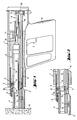
- Fig. 1 ein Bolzensetzgerät in Zündbereitschaftsstellung, teilweise im Längsschnitt;
- Fig. 2 den Vorderbereich des Bolzensetzgerätes nach Fig. 1, in Ruhestellung.
- Das Bolzensetzgerät verfügt über ein Gehäuse 1 mit einem seitlich abragenden Handgriff 1a. Im Handgriff 1a ist ein Trigger 2 gelagert. Im vorderen Bereich des Gehäuses 1 ist ein Lauf 3 verschiebbar angeordnet. An den Lauf 3 schliesst vorderseitig ein Laufmündungsteil 4 an. Der axial unverschieblichen, um die Achse des Laufes 3 verdrehbaren Halterung des Laufmündungsteiles 4 dient ein Riegel 5. Dieser sitzt in einem Durchbruch 3a des Laufes 3 und wird von einer Ringfeder 6 in Eingriff mit einer Ringnut 4a des Laufmündungsteiles 4 gehalten. Der Dreharretierung des Laufmündungsteiles 4 in beliebiger Drehstellung dient ein im Laufmündungsteil 4 sitzender Rastbolzen 7, der von einer Druckfeder 8 gegen die Rastvertiefungen 3b aufweisende vordere Stirnseite des Laufes 3 gedrückt wird. Im Laufmündungsteil 4 ist ein stabförmiges Tastglied 9 verschiebbar gelagert, welches das Laufmündungsteil 4 wechselweise entweder nach vorne oder nach hinten überragt. Die Verschiebbarkeit des Tastgliedes 9 wird durch einen im Laufmündungsteil 4 sitzenden Querstift 11, der in eine Auskehlung 9a des Tastgliedes 9 einragt, begrenzt.
- Rückwärtig zum Tastglied 9 ist zwischen dem Lauf 3 und dem Gehäuse 1 eine den Lauf 3 konzentrisch umgebende Hülse 12 verschiebbar gelagert. Deren vordere dh setzrichtungsseitige Stirnseite überdeckt sich in Axialprojektion mit der rückwärtigen Stirnseite des Tastgliedes 9.
- Im Lauf 3 und im Laufmündungsteil 4 ist ein Treibkolben 13 verschiebbar gelagert. In die den Treibkolben 13 aufnehmende Laufbohrung 3c mündet rückwärtig ein Kartuschenlager 3d. Der Lauf 3 stützt sich in Zündbereitschaftsstellung unter Anpressdruck an einem Bauteil 14 ab und liegt rückwärtig an einem im Gehäuse 1 abgestützten Verschlussteil 15 an. Eine Zündeinrichtung 16 mit einem Zündstift 17, der im Verschlussteil 15 verschiebbar gelagert ist, und einer Zündfeder 18 befindet sich im rückwärtigen Gehäusebereich des Gehäuses 1. Ein vom Zündstift 17 seitlich abragender Arm 17a wirkt für das Spannen der Zündeinrichtung 16 mit einem längs der Laufachse verschiebbaren, an der Hülse 12 aufstehenden Spannstössel 19 zusammen.
- Beim Anpressen des Setzgerätes gegen das Bauteil 14 durch Druckausübung auf den Handgriff 1a wird zuerst das in Ruhestellung (Fig. 2) das Laufmündungsteil 4 überragende Tastglied 9 im Laufmündungsteil 4 entgegen der Setzrichtung verschoben. Das Tastglied 9 überträgt die Verschiebebewegung auf die Hülse 12, die ihrerseits den Spannstössel 19 entgegen der Setzrichtung gegen die Kraft der Zündfeder 18 verschiebt. Durch weiteres stärkeres Anpressen des Setzgerätes wird in der Folge auch das Laufmündungsteil 4 zusammen mit dem Tastglied 9 entgegen der Setzrichtung aus der in Fig. 2 gezeigten Ruhestellung in die der Fig. 1 entnehmbare Zündbereitschaftsstellung verschoben. Auch dieser Verschiebeweg wird zum Spannen der Zündeinrichtung 16 vom Tastglied 9 über die Hülse 12 und den Spannstössel 19 übertragen. Durch Ausrücken des Armes 17a aus der Axialprojektion des Spannstössels 19 kann der Zündstift 17 zum Zünden einer Kartusche freigegeben werden. Für den neuerlichen Angriff des Spannstössels 19 am zum Zünden in Setzrichtung gewanderten Arm 17a des Zündstiftes 17 ist eine den Stössel in Setzrichtung treibende Feder 21 vorgesehen.
- Das Laufmündungsteil 4 kann zusammen mit dem Tastglied 9 in beliebiger Drehstellung gegenüber dem Lauf 3 eingesetzt werden, da das Tastglied 9 stets die Anpresskraft zum Erlangen der Zündbereitschaftsstellung auf die ringförmige Stirnseite der Hülse 12 zu übertragen vermag.
Claims (3)
Applications Claiming Priority (2)
| Application Number | Priority Date | Filing Date | Title |
|---|---|---|---|
| DE3806833 | 1988-03-03 | ||
| DE3806833A DE3806833A1 (de) | 1988-03-03 | 1988-03-03 | Pulverkraftbetriebenes bolzensetzgeraet |
Publications (2)
| Publication Number | Publication Date |
|---|---|
| EP0330958A1 true EP0330958A1 (de) | 1989-09-06 |
| EP0330958B1 EP0330958B1 (de) | 1991-06-19 |
Family
ID=6348685
Family Applications (1)
| Application Number | Title | Priority Date | Filing Date |
|---|---|---|---|
| EP89102922A Expired - Lifetime EP0330958B1 (de) | 1988-03-03 | 1989-02-20 | Pulverkraftbetriebenes Bolzensetzgerät |
Country Status (3)
| Country | Link |
|---|---|
| US (1) | US4936714A (de) |
| EP (1) | EP0330958B1 (de) |
| DE (2) | DE3806833A1 (de) |
Cited By (3)
| Publication number | Priority date | Publication date | Assignee | Title |
|---|---|---|---|---|
| EP0341307A4 (en) * | 1987-11-25 | 1991-04-24 | Harry M. Haytayan | Powder-actuated fastener driving tool |
| FR2843328A1 (fr) * | 2002-08-08 | 2004-02-13 | Hilti Ag | Outil de scellement |
| FR2859408A1 (fr) * | 2003-09-05 | 2005-03-11 | Hilti Ag | Outil de scellement |
Families Citing this family (12)
| Publication number | Priority date | Publication date | Assignee | Title |
|---|---|---|---|---|
| DE3804846C2 (de) * | 1988-02-17 | 1995-04-27 | Westfalia Becorit Ind Tech | Hydraulisch entsperrbares Rückschlagventil, insbesondere für hydraulische Ausbausysteme |
| GB9009859D0 (en) * | 1990-05-02 | 1990-06-27 | Meco Mining Equip | A mine roof support |
| GB2274325B (en) * | 1993-01-13 | 1996-04-03 | Meco Mining Equip | A yield valve |
| US5273065A (en) * | 1993-03-23 | 1993-12-28 | Taylor Julian S | Large diameter and relatively high pressure relief valve |
| DE19521113C2 (de) * | 1995-06-09 | 1998-06-10 | Rheinmetall Ind Ag | Bolzensetzgerät |
| IL157111A0 (en) | 2003-07-27 | 2004-02-08 | Iscar Ltd | Milling cutter and insert therefor |
| IL170837A (en) | 2005-09-13 | 2009-11-18 | Robi Nudelman | Cutting insert |
| RU2323340C1 (ru) * | 2006-09-12 | 2008-04-27 | Открытое акционерное общество "Подмосковный научно-исследовательский и проектно-конструкторский угольный институт" (АО "ПНИУИ") | Гидрораспределитель секции механизированной крепи |
| KR100985597B1 (ko) * | 2008-08-20 | 2010-10-05 | 대구텍 유한회사 | 절삭 인서트 및 이러한 절삭 인서트가 적용된 밀링커터 |
| IL203283A (en) * | 2010-01-13 | 2014-02-27 | Iscar Ltd | Cutting put |
| DE102010006223A1 (de) * | 2010-01-28 | 2011-08-18 | Voß, Wolfgang, 58239 | Druckbegrenzungsventil mit einer Sitzventildichtung |
| CN104763456B (zh) * | 2015-03-17 | 2017-03-01 | 国投新集能源股份有限公司 | 采煤坑道收作巷或回空区支撑支架及回撤液压支架的方法 |
Citations (3)
| Publication number | Priority date | Publication date | Assignee | Title |
|---|---|---|---|---|
| US3945548A (en) * | 1973-09-19 | 1976-03-23 | Roger Dorgnon | Piston actuated fastening gun |
| US4358041A (en) * | 1980-06-12 | 1982-11-09 | Olin Corporation | Powder-actuated tool with power adjustment and angle-fire control |
| EP0238917A1 (de) * | 1986-03-25 | 1987-09-30 | VALSELLA MECCANOTECNICA S.p.A. | Mit Hilfsmitteln zur Befestigung an einer Tragwand versehene Vorrichtung |
Family Cites Families (12)
| Publication number | Priority date | Publication date | Assignee | Title |
|---|---|---|---|---|
| FR1222473A (fr) * | 1957-10-25 | 1960-06-10 | Soupape et ses applications aux étançons de mines | |
| DE1200089B (de) * | 1958-12-13 | 1965-09-02 | Bosch Gmbh Robert | Federbelastetes UEberdruckventil |
| US3236256A (en) * | 1963-01-28 | 1966-02-22 | Bendix Westinghouse Automotive | Pressure protection valve |
| US3410304A (en) * | 1966-01-19 | 1968-11-12 | Herman L. Paul Jr. | Relief valves |
| FR1501974A (fr) * | 1966-09-30 | 1967-11-18 | Alsthom Cgee | Valve ultra-rapide compensée |
| DE2506928C3 (de) * | 1975-02-19 | 1979-06-28 | Gewerkschaft Eisenhuette Westfalia, 4670 Luenen | Gebirgsschlagventil für hydraulische Grubenstempel |
| DE2636794C2 (de) * | 1975-09-09 | 1982-06-09 | Voest-Alpine AG, 1011 Wien | Gebirgsschlagventil für hydraulische Grubenausbauelemente |
| DE2914981C3 (de) * | 1979-04-12 | 1993-12-02 | Westfalia Becorit Ind Tech | Druckbegrenzungsventil für hydraulische Grubenstempel |
| GB2115047B (en) * | 1982-02-03 | 1985-06-19 | Dowty Mining Equipment Ltd | Mine roof support system |
| DE3212747A1 (de) * | 1982-04-06 | 1983-10-06 | Gewerk Eisenhuette Westfalia | Einrichtung zur hubsteuerung einer zylinddergruppe eines hydraulischen ausbausystems, insbesondere zum setzen der stempel einer schreitausbaueinheit |
| GB2152635A (en) * | 1984-01-05 | 1985-08-07 | Dobson Park Ind | Valve devices |
| DE3523548A1 (de) * | 1985-07-02 | 1987-01-15 | Gewerk Eisenhuette Westfalia | Druckbegrenzungsventil |
-
1988
- 1988-03-03 DE DE3806833A patent/DE3806833A1/de not_active Withdrawn
-
1989
- 1989-02-20 EP EP89102922A patent/EP0330958B1/de not_active Expired - Lifetime
- 1989-02-20 DE DE8989102922T patent/DE58900148D1/de not_active Expired - Lifetime
- 1989-02-27 US US07/316,289 patent/US4936714A/en not_active Expired - Fee Related
Patent Citations (3)
| Publication number | Priority date | Publication date | Assignee | Title |
|---|---|---|---|---|
| US3945548A (en) * | 1973-09-19 | 1976-03-23 | Roger Dorgnon | Piston actuated fastening gun |
| US4358041A (en) * | 1980-06-12 | 1982-11-09 | Olin Corporation | Powder-actuated tool with power adjustment and angle-fire control |
| EP0238917A1 (de) * | 1986-03-25 | 1987-09-30 | VALSELLA MECCANOTECNICA S.p.A. | Mit Hilfsmitteln zur Befestigung an einer Tragwand versehene Vorrichtung |
Cited By (3)
| Publication number | Priority date | Publication date | Assignee | Title |
|---|---|---|---|---|
| EP0341307A4 (en) * | 1987-11-25 | 1991-04-24 | Harry M. Haytayan | Powder-actuated fastener driving tool |
| FR2843328A1 (fr) * | 2002-08-08 | 2004-02-13 | Hilti Ag | Outil de scellement |
| FR2859408A1 (fr) * | 2003-09-05 | 2005-03-11 | Hilti Ag | Outil de scellement |
Also Published As
| Publication number | Publication date |
|---|---|
| DE3806833A1 (de) | 1989-09-14 |
| EP0330958B1 (de) | 1991-06-19 |
| US4936714A (en) | 1990-06-26 |
| DE58900148D1 (de) | 1991-07-25 |
Similar Documents
| Publication | Publication Date | Title |
|---|---|---|
| EP0330958B1 (de) | Pulverkraftbetriebenes Bolzensetzgerät | |
| EP0346275B1 (de) | Pulverkraftbetriebenes Setzgerät | |
| EP0467835B1 (de) | Pulverkraftbetriebenes Setzgerät | |
| EP0835726B1 (de) | Pulverkraftbetriebenes Setzgerät mit Magazin für Befestigungselemente | |
| DE69906833T2 (de) | Befestigungsgerät mit durch Druckluft angetriebenem Kolben | |
| EP0370952A1 (de) | Tragbares Handgerät mit Schlagwerk | |
| DE1905000A1 (de) | Handbetaetigter Gasanzuender | |
| CH678830A5 (de) | ||
| EP1025960B1 (de) | Setzgerät | |
| EP0775554B1 (de) | Bolzensetzgerät mit Stossdämpfer | |
| EP0467834B1 (de) | Pulverkraftbetriebenes Setzgerät | |
| DE952789C (de) | Schiessvorrichtung fuer Verankerungsgeschosse | |
| EP0437736B1 (de) | Herausnehmbares Gewehrschloss | |
| EP0331168A1 (de) | Pulverkraftbetriebenes Bolzensetzgerät | |
| DE1603843C3 (de) | Pulverkraftbetriebenes Bolzensetzgerät der Treibkolbenbauart | |
| EP0200037B1 (de) | Vorrichtung für die Halterung eines Schneidmeissels sowie für die Steuerung der Bedüsungsmittelzufuhr bei einer Vortriebsmaschine | |
| DE3703753C2 (de) | ||
| DE10346985A1 (de) | Handgeführtes Setzgerät | |
| DE2333887C2 (de) | Pulverkraftbetriebenes Setzgerät | |
| DE10358576A1 (de) | Brennkraftbetriebenes Setzgerät | |
| DE10341821A1 (de) | Setzgerät | |
| DE2417333C3 (de) | Vor- und Rücklaufeinrichtung an einer selbsttätigen Feuerwaffe | |
| DE1478774C (de) | Brennkraftbolzensetzer mit zwei gegen Federkraft relativ zueinander verschiebba ren Laufteilen | |
| DE2947528C2 (de) | Schlagschrauber | |
| DE19521113C2 (de) | Bolzensetzgerät |
Legal Events
| Date | Code | Title | Description |
|---|---|---|---|
| PUAI | Public reference made under article 153(3) epc to a published international application that has entered the european phase |
Free format text: ORIGINAL CODE: 0009012 |
|
| AK | Designated contracting states |
Kind code of ref document: A1 Designated state(s): CH DE FR GB LI SE |
|
| 17P | Request for examination filed |
Effective date: 19890923 |
|
| 17Q | First examination report despatched |
Effective date: 19901114 |
|
| GRAA | (expected) grant |
Free format text: ORIGINAL CODE: 0009210 |
|
| AK | Designated contracting states |
Kind code of ref document: B1 Designated state(s): CH DE FR GB LI SE |
|
| REF | Corresponds to: |
Ref document number: 58900148 Country of ref document: DE Date of ref document: 19910725 |
|
| ET | Fr: translation filed | ||
| GBT | Gb: translation of ep patent filed (gb section 77(6)(a)/1977) | ||
| PLBE | No opposition filed within time limit |
Free format text: ORIGINAL CODE: 0009261 |
|
| STAA | Information on the status of an ep patent application or granted ep patent |
Free format text: STATUS: NO OPPOSITION FILED WITHIN TIME LIMIT |
|
| 26N | No opposition filed | ||
| PGFP | Annual fee paid to national office [announced via postgrant information from national office to epo] |
Ref country code: SE Payment date: 19931110 Year of fee payment: 6 |
|
| EAL | Se: european patent in force in sweden |
Ref document number: 89102922.5 |
|
| PG25 | Lapsed in a contracting state [announced via postgrant information from national office to epo] |
Ref country code: SE Effective date: 19950221 |
|
| EUG | Se: european patent has lapsed |
Ref document number: 89102922.5 |
|
| PGFP | Annual fee paid to national office [announced via postgrant information from national office to epo] |
Ref country code: GB Payment date: 20000216 Year of fee payment: 12 |
|
| PGFP | Annual fee paid to national office [announced via postgrant information from national office to epo] |
Ref country code: CH Payment date: 20010213 Year of fee payment: 13 |
|
| PG25 | Lapsed in a contracting state [announced via postgrant information from national office to epo] |
Ref country code: GB Free format text: LAPSE BECAUSE OF NON-PAYMENT OF DUE FEES Effective date: 20010220 |
|
| GBPC | Gb: european patent ceased through non-payment of renewal fee |
Effective date: 20010220 |
|
| PG25 | Lapsed in a contracting state [announced via postgrant information from national office to epo] |
Ref country code: LI Free format text: LAPSE BECAUSE OF NON-PAYMENT OF DUE FEES Effective date: 20020228 Ref country code: CH Free format text: LAPSE BECAUSE OF NON-PAYMENT OF DUE FEES Effective date: 20020228 |
|
| REG | Reference to a national code |
Ref country code: CH Ref legal event code: PL |
|
| PGFP | Annual fee paid to national office [announced via postgrant information from national office to epo] |
Ref country code: DE Payment date: 20080124 Year of fee payment: 20 |
|
| PGFP | Annual fee paid to national office [announced via postgrant information from national office to epo] |
Ref country code: FR Payment date: 20080208 Year of fee payment: 20 |