EP0331005A2 - Dispositif pour ventiler un local - Google Patents
Dispositif pour ventiler un local Download PDFInfo
- Publication number
- EP0331005A2 EP0331005A2 EP89103158A EP89103158A EP0331005A2 EP 0331005 A2 EP0331005 A2 EP 0331005A2 EP 89103158 A EP89103158 A EP 89103158A EP 89103158 A EP89103158 A EP 89103158A EP 0331005 A2 EP0331005 A2 EP 0331005A2
- Authority
- EP
- European Patent Office
- Prior art keywords
- electric motor
- switch
- run
- control device
- housing
- Prior art date
- Legal status (The legal status is an assumption and is not a legal conclusion. Google has not performed a legal analysis and makes no representation as to the accuracy of the status listed.)
- Withdrawn
Links
Images
Classifications
-
- F—MECHANICAL ENGINEERING; LIGHTING; HEATING; WEAPONS; BLASTING
- F24—HEATING; RANGES; VENTILATING
- F24F—AIR-CONDITIONING; AIR-HUMIDIFICATION; VENTILATION; USE OF AIR CURRENTS FOR SCREENING
- F24F11/00—Control or safety arrangements
- F24F11/0001—Control or safety arrangements for ventilation
-
- F—MECHANICAL ENGINEERING; LIGHTING; HEATING; WEAPONS; BLASTING
- F24—HEATING; RANGES; VENTILATING
- F24F—AIR-CONDITIONING; AIR-HUMIDIFICATION; VENTILATION; USE OF AIR CURRENTS FOR SCREENING
- F24F13/00—Details common to, or for air-conditioning, air-humidification, ventilation or use of air currents for screening
- F24F13/08—Air-flow control members, e.g. louvres, grilles, flaps or guide plates
- F24F13/10—Air-flow control members, e.g. louvres, grilles, flaps or guide plates movable, e.g. dampers
- F24F13/14—Air-flow control members, e.g. louvres, grilles, flaps or guide plates movable, e.g. dampers built up of tilting members, e.g. louvre
- F24F13/15—Air-flow control members, e.g. louvres, grilles, flaps or guide plates movable, e.g. dampers built up of tilting members, e.g. louvre with parallel simultaneously tiltable lamellae
Definitions
- the invention relates to a device for ventilating a room, in particular a toilet, consisting of a fan wheel which is arranged in a housing and can be driven by an electric motor which can be connected as required.
- a device for actuating a fan provided with a flap in which the flap is opened by a heating bimetallic strip and is held in the open position in the heated state.
- the flap When the bimetal strip cools, the flap returns to its closed position.
- an electrical heating element which is in heat-conducting contact with the bimetal strip. Since the heating of the heating element and thus the bimetallic strip takes place relatively slowly, the electric motor that drives the fan wheel must be switched on with a delay.
- a special thermal switch is provided in the circuit of the fan motor, which is in heat-conducting contact with the bimetal strip.
- the circuit for the electric motor of the fan wheel is closed.
- the bimetal strip and the thermal switch cool down again.
- the temperature switch opens, the power supply to the electric motor is interrupted and the fan wheel is stopped.
- the delay of the electric motor when switching on and off is dependent on the heating and cooling of the thermal switch and thus on the heating and cooling of the heating element.
- the invention is therefore based on the object of providing a device for ventilating a room, in particular a toilet, which takes effect immediately or within a very short time when an operating switch is actuated and in which the run-on time of the electric motor can be set precisely to a predetermined value or is changeable.
- a digital follow-up control device with a circuit breaker (TRIAC) for the electric motor which can be controlled by a switch or a button is arranged in the housing.
- TRIAC circuit breaker
- This arrangement has the advantage that the electric motor starts immediately when the operating switch is closed and comes into effect immediately when the fan flaps are opened.
- the run-on control device enables a precise setting of the run-on time of the electric motor, the run-on time being changeable.
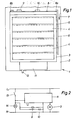
- FIG. 1 of the drawing shows a device 1 which is used, for example, to ventilate a toilet.
- This device 1 consists of a base plate 2, with which the device 1 is fastened in a known manner, not shown, in the region of a ventilation opening or the like.
- the base plate 2 carries an electric motor 3 (FIG. 2) with a fan wheel on its rear side.
- a frame 3 On the front or front side of the base plate 2, a frame 3 is provided, in which a plurality of fan flaps 4 are pivotally mounted about axes, not shown.
- each axis of a fan flap 4 is connected to a lever 5, all of the levers 5 being connected to a common rod 6. By moving the rod 6 in the direction of arrow 7, all fan flaps 4 can be moved from their closed position to an open position.
- the rod 6 is connected at one end to the free end 8a of a bimetallic strip 8, which is clamped in place at its other end 8b.
- the bimetal strip 8 carries a heating element 9, which is designed as a PTC resistor element or PTC resistor.
- a second heating element 10 which is designed in the same way as the heating element 9.
- a housing is provided on the base plate 2, which connects to the lower side of the frame 3 and accommodates a digital run-on control device with a circuit breaker (TRIAC).
- the run-on control device has one adjustable timer, which is provided with an adjusting lever 12.
- the operating switch 13 can be formed by a light switch, a door contact or a button.
- the operating switch 13 When the device 1 is started up, the operating switch 13 is first closed. On the one hand, this causes the room lighting 14 to be switched on. On the other hand, this closes the circuits for the run-on control device and the two heating elements 9, 10.
- the circuit breaker is immediately effective via the run-on control device, thus releasing the circuit for the electric motor 3 so that the fan wheel starts up immediately.
- the heating elements 9, 10 become hot within a very short time and heat the bimetallic strip 8, which is deformed by the heat, so that all the fan flaps 4 are opened via the rod 6.
- the opening process of the ventilation flaps 4 is completed by the two heating elements 9, 10 at the latest after 10 seconds, so that the ventilation is then fully effective.
- the digital run-on control unit works on the basis of a number comparison stage. Appropriate programming specifies a numerical value. By opening the shop switch 13, the digital run-on control device is activated, counts and adds pulses and switches off the circuit breaker (TRIAC) and thus the electric motor 3 when the predetermined / given numerical value is reached. The time that the electric motor 3 should run on can thus be set very precisely. If necessary, this time can be set using the lever 12 of a timer assigned to the run-on control device.
- TRIAC circuit breaker
- the room lighting 14 is switched off and the circuit to the heating elements 9, 10 is also interrupted.
- the heating elements 9, 10 and the bimetallic strip 8 can now cool down.
- all fan flaps 4 are closed.
- the run-on time of the electric motor 3 is expediently chosen so that it switches off approximately simultaneously with the closing of the fan flap 4.
Landscapes
- Engineering & Computer Science (AREA)
- Chemical & Material Sciences (AREA)
- Combustion & Propulsion (AREA)
- Mechanical Engineering (AREA)
- General Engineering & Computer Science (AREA)
- Motor And Converter Starters (AREA)
- Ventilation (AREA)
Applications Claiming Priority (2)
| Application Number | Priority Date | Filing Date | Title |
|---|---|---|---|
| DE8802774U | 1988-03-02 | ||
| DE8802774U DE8802774U1 (de) | 1988-03-02 | 1988-03-02 | Vorrichtung zum Belüften eines Raumes |
Publications (1)
| Publication Number | Publication Date |
|---|---|
| EP0331005A2 true EP0331005A2 (fr) | 1989-09-06 |
Family
ID=6821336
Family Applications (1)
| Application Number | Title | Priority Date | Filing Date |
|---|---|---|---|
| EP89103158A Withdrawn EP0331005A2 (fr) | 1988-03-02 | 1989-02-23 | Dispositif pour ventiler un local |
Country Status (2)
| Country | Link |
|---|---|
| EP (1) | EP0331005A2 (fr) |
| DE (1) | DE8802774U1 (fr) |
Cited By (2)
| Publication number | Priority date | Publication date | Assignee | Title |
|---|---|---|---|---|
| GB2302221A (en) * | 1995-06-13 | 1997-01-08 | Barry Conway | Room ventilating system |
| ES2209652A1 (es) * | 2002-12-10 | 2004-06-16 | Soler Y Palau, S.A. | Extractor de baño de funcionamiento temporizado. |
-
1988
- 1988-03-02 DE DE8802774U patent/DE8802774U1/de not_active Expired
-
1989
- 1989-02-23 EP EP89103158A patent/EP0331005A2/fr not_active Withdrawn
Cited By (4)
| Publication number | Priority date | Publication date | Assignee | Title |
|---|---|---|---|---|
| GB2302221A (en) * | 1995-06-13 | 1997-01-08 | Barry Conway | Room ventilating system |
| GB2302221B (en) * | 1995-06-13 | 1997-06-18 | Barry Conway | Room ventilation systems |
| ES2209652A1 (es) * | 2002-12-10 | 2004-06-16 | Soler Y Palau, S.A. | Extractor de baño de funcionamiento temporizado. |
| WO2004053399A1 (fr) * | 2002-12-10 | 2004-06-24 | Soler Y Palau, S.A. | Extracteur pour salle de bain a fonctionnement temporise |
Also Published As
| Publication number | Publication date |
|---|---|
| DE8802774U1 (de) | 1988-05-26 |
Similar Documents
| Publication | Publication Date | Title |
|---|---|---|
| DE2440133A1 (de) | Verriegelungsvorrichtung fuer waschmaschinentueren | |
| DE3908136A1 (de) | Regelung fuer brenner von heizanlagen | |
| DE2824510C2 (de) | Vorrichtung zum Steuern der Bewegung eines angetriebenen Tores | |
| DE1941338A1 (de) | Elektrische Schaltung fuer einen selbstreinigenden Ofen | |
| EP0331005A2 (fr) | Dispositif pour ventiler un local | |
| DE3737712C2 (fr) | ||
| DE2551925C2 (de) | Fotografische Belichtungssteuervorrichtung | |
| DE19831119C2 (de) | Garagentorantrieb | |
| DE2800968A1 (de) | Anordnung zur steuerung von sonnenschutzeinrichtungen mit vertikalen lamellen | |
| DE2628150C3 (de) | Schaltanordnung zum Beheizen eines Schlosses von Kraftfahrzeugen | |
| DE2017422C3 (de) | Selbsttätige Sicherheitsschaltung zur Überwachung des Leistungsschaltgliedes eines elektrischen Stromverbrauchers | |
| DE3100232C2 (fr) | ||
| DE1260651B (de) | Temperaturregeleinrichtung | |
| EP0629103B1 (fr) | Procédé et circuit pour le contrÔle de la température d'un appareil de chauffage à courant alternatif | |
| DE9401350U1 (de) | Vorrichtung zum Be- und/oder Entlüften von Räumen | |
| DE9203267U1 (de) | Schaltung für eine Heizerbaugruppe | |
| DE2111070A1 (de) | Back- und Bratofen | |
| EP0554812B1 (fr) | Dispositif de diminution manuelle de température de minuterie pour un thermostat | |
| DE2150311A1 (de) | Temperaturabhaengiger elektrischer schalter mit einem bimetallischen steuerorgan | |
| EP0331006A2 (fr) | Dispositif pour ventiler un local | |
| DE3100231A1 (de) | "vorrichtung zum betaetigen von verschlusseinrichtungen lueftungstechnischer anlagen" | |
| DE3039273A1 (de) | Verriegelungseinrichtung fuer backoefen mit einer einrichtung zur pyrolytischen selbstreinigung | |
| DE1266143B (de) | Schalteinrichtung fuer Stellmotoren in Kraftfahrzeugen | |
| DE1295783B (de) | Elektrische Steuereinrichtung fuer mit stroemendem Brennstoff betriebene Brenner | |
| DE680503C (de) | Waermezeitschalter mit abwechselnd zu beheizenden Schaltkoerpern |
Legal Events
| Date | Code | Title | Description |
|---|---|---|---|
| PUAI | Public reference made under article 153(3) epc to a published international application that has entered the european phase |
Free format text: ORIGINAL CODE: 0009012 |
|
| AK | Designated contracting states |
Kind code of ref document: A2 Designated state(s): AT BE CH DE ES FR GB GR IT LI LU NL SE |
|
| 18D | Application deemed to be withdrawn |
Effective date: 19910829 |