EP0331028A1 - Verfahren zur Reinigung von Rohargon - Google Patents
Verfahren zur Reinigung von Rohargon Download PDFInfo
- Publication number
- EP0331028A1 EP0331028A1 EP89103255A EP89103255A EP0331028A1 EP 0331028 A1 EP0331028 A1 EP 0331028A1 EP 89103255 A EP89103255 A EP 89103255A EP 89103255 A EP89103255 A EP 89103255A EP 0331028 A1 EP0331028 A1 EP 0331028A1
- Authority
- EP
- European Patent Office
- Prior art keywords
- crude argon
- argon
- liquid
- gaseous
- crude
- Prior art date
- Legal status (The legal status is an assumption and is not a legal conclusion. Google has not performed a legal analysis and makes no representation as to the accuracy of the status listed.)
- Granted
Links
Images
Classifications
-
- F—MECHANICAL ENGINEERING; LIGHTING; HEATING; WEAPONS; BLASTING
- F25—REFRIGERATION OR COOLING; COMBINED HEATING AND REFRIGERATION SYSTEMS; HEAT PUMP SYSTEMS; MANUFACTURE OR STORAGE OF ICE; LIQUEFACTION SOLIDIFICATION OF GASES
- F25J—LIQUEFACTION, SOLIDIFICATION OR SEPARATION OF GASES OR GASEOUS OR LIQUEFIED GASEOUS MIXTURES BY PRESSURE AND COLD TREATMENT OR BY BRINGING THEM INTO THE SUPERCRITICAL STATE
- F25J3/00—Processes or apparatus for separating the constituents of gaseous or liquefied gaseous mixtures involving the use of liquefaction or solidification
- F25J3/02—Processes or apparatus for separating the constituents of gaseous or liquefied gaseous mixtures involving the use of liquefaction or solidification by rectification, i.e. by continuous interchange of heat and material between a vapour stream and a liquid stream
- F25J3/04—Processes or apparatus for separating the constituents of gaseous or liquefied gaseous mixtures involving the use of liquefaction or solidification by rectification, i.e. by continuous interchange of heat and material between a vapour stream and a liquid stream for air
- F25J3/04642—Recovering noble gases from air
- F25J3/04648—Recovering noble gases from air argon
- F25J3/04721—Producing pure argon, e.g. recovered from a crude argon column
- F25J3/04733—Producing pure argon, e.g. recovered from a crude argon column using a hybrid system, e.g. using adsorption, permeation or catalytic reaction
- F25J3/04739—Producing pure argon, e.g. recovered from a crude argon column using a hybrid system, e.g. using adsorption, permeation or catalytic reaction in combination with an auxiliary pure argon column
-
- C—CHEMISTRY; METALLURGY
- C01—INORGANIC CHEMISTRY
- C01B—NON-METALLIC ELEMENTS; COMPOUNDS THEREOF; METALLOIDS OR COMPOUNDS THEREOF NOT COVERED BY SUBCLASS C01C
- C01B23/00—Noble gases; Compounds thereof
-
- F—MECHANICAL ENGINEERING; LIGHTING; HEATING; WEAPONS; BLASTING
- F25—REFRIGERATION OR COOLING; COMBINED HEATING AND REFRIGERATION SYSTEMS; HEAT PUMP SYSTEMS; MANUFACTURE OR STORAGE OF ICE; LIQUEFACTION SOLIDIFICATION OF GASES
- F25J—LIQUEFACTION, SOLIDIFICATION OR SEPARATION OF GASES OR GASEOUS OR LIQUEFIED GASEOUS MIXTURES BY PRESSURE AND COLD TREATMENT OR BY BRINGING THEM INTO THE SUPERCRITICAL STATE
- F25J2205/00—Processes or apparatus using other separation and/or other processing means
- F25J2205/82—Processes or apparatus using other separation and/or other processing means using a reactor with combustion or catalytic reaction
-
- F—MECHANICAL ENGINEERING; LIGHTING; HEATING; WEAPONS; BLASTING
- F25—REFRIGERATION OR COOLING; COMBINED HEATING AND REFRIGERATION SYSTEMS; HEAT PUMP SYSTEMS; MANUFACTURE OR STORAGE OF ICE; LIQUEFACTION SOLIDIFICATION OF GASES
- F25J—LIQUEFACTION, SOLIDIFICATION OR SEPARATION OF GASES OR GASEOUS OR LIQUEFIED GASEOUS MIXTURES BY PRESSURE AND COLD TREATMENT OR BY BRINGING THEM INTO THE SUPERCRITICAL STATE
- F25J2230/00—Processes or apparatus involving steps for increasing the pressure of gaseous process streams
- F25J2230/58—Processes or apparatus involving steps for increasing the pressure of gaseous process streams the fluid being argon or crude argon
-
- Y—GENERAL TAGGING OF NEW TECHNOLOGICAL DEVELOPMENTS; GENERAL TAGGING OF CROSS-SECTIONAL TECHNOLOGIES SPANNING OVER SEVERAL SECTIONS OF THE IPC; TECHNICAL SUBJECTS COVERED BY FORMER USPC CROSS-REFERENCE ART COLLECTIONS [XRACs] AND DIGESTS
- Y10—TECHNICAL SUBJECTS COVERED BY FORMER USPC
- Y10S—TECHNICAL SUBJECTS COVERED BY FORMER USPC CROSS-REFERENCE ART COLLECTIONS [XRACs] AND DIGESTS
- Y10S62/00—Refrigeration
- Y10S62/923—Inert gas
- Y10S62/924—Argon
Definitions
- the invention relates to a process for the purification of crude argon, which is partly liquid, partly gaseous, in which the liquid crude argon evaporates under increased pressure, the oxygen contained in the crude argon is reduced to water with supplied hydrogen, the water formed is separated from the gas mixture and the remaining gas mixture is cooled and broken down by rectification into a liquid pure argon fraction and a residual gas fraction.
- Raw argon is a mixture that contains about 90 to 99% (by volume) of argon and also small amounts of oxygen and nitrogen. Such a mixture occurs, for example, in the head of a crude argon column, which is connected to a plant for the low-temperature separation of air.
- the raw argon In order to obtain pure argon (approx. 99.999%) from raw argon, the raw argon has to be purified, for example by rectification in a pure argon column.
- the object of the present invention is to make such a process more economical, in particular by increasing the argon yield.
- This object is achieved in that the gaseous crude argon is compressed and is fed to the liquid crude argon after evaporation.
- the gaseous raw argon is not lost in this way for the production of pure argon, but contributes to an overall very high argon yield.
- the advantage of A favorable way of increasing the pressure of the liquid raw argon can be obtained. It must be taken into account that part of the raw argon must always be removed in gaseous form in the usual raw argon production, so that the top condenser of the raw argon column is not blocked by non-condensable gases.
- the gaseous crude argon is condensed and fed to the liquid crude argon before the pressure increase.
- the crude argon obtained in gaseous form can be compressed without an additional compression device.
- the condensation required for this can be carried out inexpensively in heat exchange with product or intermediate product streams from the system.
- a raw argon column 2 is connected via a feed line 1 and a discharge line 3 to a system for air separation, not shown.
- the crude argon column 2 is operated under a pressure of 1.1 to 3 bar, usually about 1.2 bar.
- Raw argon with a temperature of 88 to 100 K, preferably 89 K, is obtained as the top product.
- Raw argon consists of 90 to 99%, preferably approximately 95% argon and also contains oxygen and nitrogen.
- the largest part (80 to 97%, preferably 90 to 95%) of the raw argon is removed in the liquid state via a liquid line 4.
- the gradient in the liquid line 4 is so great that the pressure of the liquid raw argon is increased to 3 to 5, preferably 4 bar.
- the liquid crude argon is then evaporated in a heat exchanger 6 in countercurrent to a heating gas (for example air or nitrogen).
- Hydrogen is fed in via line 8, with which the oxygen contained in the crude argon is reduced to water in a reactor 9. This is followed by a dryer 10 in which the water formed in the reaction is separated off.
- the remaining gas mixture essentially contains argon, nitrogen and hydrogen, which is usually mixed in excess in front of the reactor 9 in order to ensure the complete removal of the oxygen.
- the gas mixture is heated in the heat exchanger 11 in countercurrent to nitrogen in line 12 and fed to the bottom heater of a pure argon column 13, where it is largely liquefied.
- the now liquid portion of the mixture is passed on via line 14, relaxed, introduced into the pure argon column 13 and subjected there to rectification, which is carried out under a pressure of 1.2 to 2 bar, preferably 1.5 bar.
- the head of the pure argon column 13 is cooled by liquid nitrogen (line 17). Liquid argon 15 and residual gas 16 are removed as product fractions.
- the gaseous fraction of the mixture used for the sump heating which contains the excess hydrogen, is led out of the sump heating via line 18, heated in the heat exchanger 11, compressed in a compressor 19 and mixed with the crude argon in front of the reactor 9.
- a small part of the crude argon (3 to 20%, preferably 5 to 10%) is removed in a gaseous state via a gas line 5.
- This gaseous crude argon removed is cooled in the heat exchanger 6 and compressed according to the invention (19) and fed to the crude argon removed in liquid form, which has been evaporated in the heat exchanger 6.
- the returned hydrogen-containing gas and the gaseous crude argon removed are compressed together in the compressor 19.
Landscapes
- Chemical & Material Sciences (AREA)
- Engineering & Computer Science (AREA)
- Organic Chemistry (AREA)
- Chemical Kinetics & Catalysis (AREA)
- Physics & Mathematics (AREA)
- Mechanical Engineering (AREA)
- Thermal Sciences (AREA)
- General Engineering & Computer Science (AREA)
- Inorganic Chemistry (AREA)
- Separation By Low-Temperature Treatments (AREA)
Abstract
Description
- Die Erfindung betrifft ein Verfahren zur Reinigung von Rohargon, das teils flüssig, teils gasförmig anfällt, bei dem das flüssig angefallene Rohargon unter erhöhtem Druck verdampft, der im Rohargon enthaltene Sauerstoff mit zugeführtem Wasserstoff zu Wasser reduziert, das gebildete Wasser aus dem Gasgemisch abgetrennt und das verbleibende Gasgemisch abgekühlt und durch Rektifikation in eine flüssige Reinargonfraktion und eine Restgasfraktion zerlegt wird.
- Als Rohargon wird ein Gemisch bezeichnet, das etwa 90 bis 99% (bezogen auf das Volumen) Argon und außerdem geringe Mengen von Sauerstoff und Stickstoff enthält. Ein solches Gemisch fällt beispielsweise im Kopf einer Rohargonsäule an, die an eine Anlage zur Tieftemperaturzerlegung von Luft angeschlossen ist. Um aus Rohargon reines Argon (ca. 99,999%) zu gewinnen, muß das Rohargon gereinigt werden, beispielsweise durch Rektifikation in einer Reinargonsäule.
- Bei einem Verfahren dieser Art, das aus der DE-OS 34 28 968 (Fig. 2) bekannt ist, wird Rohargon flüssig aus dem Kopf der Rohargonsäule entnommen. Um Betriebsstörungen in der Rohargonsäule zu verhindern, wird ein Teil des Rohargons gasförmig herausgeführt und zur Luftzerlegung zurückgeleitet. Das flüssig entnommene Rohargon erfährt eine Druckerhöhung unter Ausnützung seines hydrostatischen Potentials und wird anschließend verdampft. Nach dem Zumischen von Wasserstoff wird der im Rohargon enthaltene Sauerstoff reduziert und das entstandene Wasser in einem Trockner entfernt. Das verbleibende Gasgemisch wird abgekühlt und schließlich in die Reinargonsäule eingeleitet.
- Ein solches Verfahren ist zwar einerseits günstig, da zur Erhöhung des Drucks des Rohargons keine Maschine benötigt wird, andererseits ist es wirtschaftlich nicht zufriedenstellend, insbesondere dadurch, daß ein Teil des bereits gewonnenen Rohargons wieder zur Luftzerlegung zurückgeführt wird, also bereits geleistete Trennarbeit dem Verfahren verlorengeht.
- Die Aufgabe der vorliegenden Erfindung besteht darin, ein solches Verfahren wirtschaftlich günstiger zu gestalten, insbesondere durch Erhöhung der Argonausbeute.
- Diese Aufgabe wird dadurch gelöst, daß das gasförmig angefallene Rohargon verdichtet und dem flüssig angefallenen Rohargon nach dem Verdampfen zugeführt wird. Das gasförmig angefallene Rohargon geht auf diese Weise für die Reinargongewinnnung nicht verloren, sondern trägt zu einer insgesamt sehr hohen Argonausbeute bei. Der Vorteil der günstigen Art der Erhöhung des Drucks des flüssig entnommenen Rohargons kann dabei erhalten werden. Dabei ist zu berücksichtigen, daß bei der üblichen Rohargongewinnung ein Teil des Rohargons immer gasförmig entnommen werden muß, damit der Kopfkondensator der Rohargonsäule nicht durch nichtkondensierbare Gase blockiert wird.
- Die Vorteile des erfindungsgemäßen Verfahrens kommen besonders zum Tragen, wenn nach dem Abtrennen des Wassers ein wasserstoffhaltiges Gas vom verbleibenden Gasgemisch abgezweigt und dem Rohargon vor dem Reduzieren wieder zugeführt wird und wenn das gasförmig angefallene Rohargon gemeinsam mit dem wasserstoffhaltigen Gas verdichtet wird. Das wasserstoffhaltige Gas muß bei dieser bekannten Art der Rückführung verdichtet werden. Erfindungsgemäß wird das gasförmig angefallene Rohargon in diesem ohnehin vorhandenen Verdichter komprimiert. Dadurch kann die hohe Argonausbeute mit sehr geringem apparativen Aufwand erreicht werden.
- In einer anderen Variante des erfindungsgemäßen Verfahrens wird das gasförmig angefallene Rohargon kondensiert und dem flüssig angefallenen Rohargon vor der Druckerhöhung zugeführt. Auch auf diese Weise kann das gasförmig angefallene Rohargon ohne eine zusätzliche Verdichtungseinrichtung komprimiert werden. Das dafür notwendige Kondensieren kann kostengünstig in Wärmetausch mit Produkt- oder Zwischenproduktströmen der Anlage durchgeführt werden.
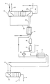
- Im folgenden werden die Erfindung sowie weitere Einzelheiten der Erfindung anhand eines in der Figur schematisch dargestellten Ausführungsbeispiels näher erläutert.
- Eine Rohargonsäule 2 ist über eine Zuführungsleitung 1 und eine Abführungsleitung 3 mit einer nicht dargestellten Anlage zur Luftzerlegung verbunden. Die Rohargonsäule 2 wird unter einem Druck von 1,1 bis 3 bar, üblicherweise etwa 1,2 bar betrieben. Als Kopfprodukt wird Rohargon mit einer Temperatur von 88 bis 100 K, vorzugsweise 89 K gewonnen. Rohargon besteht zu 90 bis 99%, vorzugsweise zu etwa 95% aus Argon und enthält darüberhinaus Sauerstoff und Stickstoff.
- Der größte Teil (80 bis 97%, vorzugsweise 90 bis 95%) des Rohargons wird über eine Flüssigkeitsleitung 4 in flüssigem Zustand entnommen. Das Gefälle in der Flüssigkeitsleitung 4 ist so groß, daß der Druck des flüssigen Rohargons auf 3 bis 5, vorzugsweise 4 bar erhöht wird. Anschließend wird das flüssige Rohargon in einem Wärmetauscher 6 im Gegenstrom zu einem Anwärmgas (beispielsweise Luft oder Stickstoff) verdampft.
- Über Leitung 8 wird Wasserstoff eingespeist, mit dem der im Rohargon enthaltene Sauerstoff in einem Reaktor 9 zu Wasser reduziert wird. Danach folgt ein Trockner 10, in dem das bei der Reaktion gebildete Wasser abgetrennt wird. Das verbleibende Gasgemisch enthält im wesentlichen Argon, Stickstoff und Wasserstoff, der vor dem Reaktor 9 in der Regel im Überschuß zugemischt wird, um die restlose Entfernung des Sauerstoffs zu gewährleisten. Das Gasgemisch wird im Wärmetauscher 11 im Gegenstrom zu Stickstoff in Leitung 12 angewärmt und der Sumpfheizung einer Reinargonsäule 13 zugeführt, wo es zum größten Teil verflüssigt wird.
- Der nunmehr flüssige Anteil des Gemisches wird über Leitung l4 weitergeführt, entspannt, in die Reinargonsäule 13 eingeführt und dort einer Rektifikation unterzogen, die unter einem Druck von 1,2 bis 2 bar, vorzugsweise 1,5 bar durchgeführt wird. Der Kopf der Reinargonsäule 13 wird dabei durch flüssigen Stickstoff (Leitung 17) gekühlt. Als Produktfraktionen werden flüssiges Argon 15 und Restgas 16 entnommen.
- Der gasförmige Anteil des zur Sumpfheizung verwendeten Gemisches, der den überschüssigen Wasserstoff enthält, wird über Leitung 18 aus der Sumpfheizung herausgeführt, im Wärmetauscher 11 angewärmt in einem Verdichter 19 komprimiert und dem Rohargon vor dem Reaktor 9 zugemischt.
- Um eine Blockierung des Kopfkondensators der Rohargonsäule 2 zu verhindern, wird ein geringer Teil des Rohargons (3 bis 20%, vorzugsweise 5 bis 10%) über eine Gasleitung 5 in gasförmigem Zustand entnommen. Dieses gasförmig entnommene Rohargon wird im Wärmetauscher 6 abgekühlt und erfindungsgemäß verdichtet (19) und dem flüssig entnommenen Rohargon, das im Wärmetauscher 6 verdampft wurde, zugeführt.
- Gemäß einem weiteren Erfindungsmerkmal werden im Verdichter 19 das rückgeführte wasserstoffhaltige Gas und das gasförmig entnommene Rohargon gemeinsam verdichtet.
Claims (3)
Applications Claiming Priority (2)
| Application Number | Priority Date | Filing Date | Title |
|---|---|---|---|
| DE3806523A DE3806523A1 (de) | 1988-03-01 | 1988-03-01 | Verfahren zur reinigung von rohargon |
| DE3806523 | 1988-03-01 |
Publications (2)
| Publication Number | Publication Date |
|---|---|
| EP0331028A1 true EP0331028A1 (de) | 1989-09-06 |
| EP0331028B1 EP0331028B1 (de) | 1991-10-30 |
Family
ID=6348511
Family Applications (1)
| Application Number | Title | Priority Date | Filing Date |
|---|---|---|---|
| EP89103255A Expired - Lifetime EP0331028B1 (de) | 1988-03-01 | 1989-02-24 | Verfahren zur Reinigung von Rohargon |
Country Status (4)
| Country | Link |
|---|---|
| US (1) | US4935044A (de) |
| EP (1) | EP0331028B1 (de) |
| JP (1) | JPH01296079A (de) |
| DE (2) | DE3806523A1 (de) |
Cited By (6)
| Publication number | Priority date | Publication date | Assignee | Title |
|---|---|---|---|---|
| US4983194A (en) * | 1990-02-02 | 1991-01-08 | Air Products And Chemicals, Inc. | Production of high purity argon |
| DE4406051A1 (de) * | 1994-02-24 | 1995-08-31 | Linde Ag | Verfahren und Vorrichtung zur Gewinnung von reinem Argon |
| DE4406049A1 (de) * | 1994-02-24 | 1995-09-07 | Linde Ag | Verfahren und Vorrichtung zur Gewinnung von reinem Argon |
| DE4406069A1 (de) * | 1994-02-24 | 1995-09-07 | Linde Ag | Verfahren und Vorrichtung zur Gewinnung von reinem Argon |
| EP0628778B2 (de) † | 1993-06-07 | 2001-03-21 | L'air Liquide, Societe Anonyme Pour L'etude Et L'exploitation Des Procedes Georges Claude | Verfahren und Hochdruckgasversorgungseinheit für eine ein Luftbestandteil verbrauchende Anlage |
| WO2020025214A1 (de) | 2018-07-28 | 2020-02-06 | Messer Group Gmbh | Verfahren zum wiederverwerten von argon |
Families Citing this family (22)
| Publication number | Priority date | Publication date | Assignee | Title |
|---|---|---|---|---|
| US5125934A (en) * | 1990-09-28 | 1992-06-30 | The Boc Group, Inc. | Argon recovery from argon-oxygen-decarburization process waste gases |
| FR2675567A1 (fr) * | 1991-04-16 | 1992-10-23 | Air Liquide | Procede et installation de production d'argon. |
| US5161380A (en) * | 1991-08-12 | 1992-11-10 | Union Carbide Industrial Gases Technology Corporation | Cryogenic rectification system for enhanced argon production |
| DE4126945A1 (de) * | 1991-08-14 | 1993-02-18 | Linde Ag | Verfahren zur luftzerlegung durch rektifikation |
| US5228296A (en) * | 1992-02-27 | 1993-07-20 | Praxair Technology, Inc. | Cryogenic rectification system with argon heat pump |
| DE4317916A1 (de) * | 1993-05-28 | 1994-12-01 | Linde Ag | Verfahren und Vorrichtung zur Gewinnung von Argon |
| CA2142318A1 (en) * | 1994-02-24 | 1995-08-25 | Horst Corduan | Process and apparatus for recovery of pure argon |
| CA2142317A1 (en) * | 1994-02-24 | 1995-08-25 | Anton Moll | Process and apparatus for the recovery of pure argon |
| US7393339B2 (en) | 2003-02-21 | 2008-07-01 | C. R. Bard, Inc. | Multi-lumen catheter with separate distal tips |
| US20040243095A1 (en) | 2003-05-27 | 2004-12-02 | Shekhar Nimkar | Methods and apparatus for inserting multi-lumen spit-tip catheters into a blood vessel |
| US8992454B2 (en) | 2004-06-09 | 2015-03-31 | Bard Access Systems, Inc. | Splitable tip catheter with bioresorbable adhesive |
| US8323227B2 (en) | 2004-07-02 | 2012-12-04 | C. R. Bard, Inc. | Tip configurations for a multi-lumen catheter |
| US20060004316A1 (en) | 2004-07-02 | 2006-01-05 | Difiore Attilio E | Reduction of recirculation in catheters |
| EP2214765A4 (de) | 2007-10-17 | 2011-08-10 | Bard Access Systems Inc | Herstellung von kathetern mit spaltspitze |
| US8066660B2 (en) | 2007-10-26 | 2011-11-29 | C. R. Bard, Inc. | Split-tip catheter including lateral distal openings |
| US8292841B2 (en) | 2007-10-26 | 2012-10-23 | C. R. Bard, Inc. | Solid-body catheter including lateral distal openings |
| US9579485B2 (en) | 2007-11-01 | 2017-02-28 | C. R. Bard, Inc. | Catheter assembly including a multi-lumen configuration |
| JP5452498B2 (ja) | 2007-11-01 | 2014-03-26 | シー・アール・バード・インコーポレーテッド | 三重管腔端を含むカテーテル組立体 |
| DE102009003350C5 (de) * | 2009-01-14 | 2017-02-09 | Reicat Gmbh | Verfahren und Vorrichtung zur Abtrennung von Argon aus einem Gasgemisch |
| US8899075B2 (en) | 2010-11-18 | 2014-12-02 | Praxair Technology, Inc. | Air separation method and apparatus |
| USD748252S1 (en) | 2013-02-08 | 2016-01-26 | C. R. Bard, Inc. | Multi-lumen catheter tip |
| WO2016011091A1 (en) | 2014-07-14 | 2016-01-21 | C. R. Bard, Inc. | Apparatuses, systems, and methods for inserting split tip catheters having enhanced stiffening and guiding features |
Citations (2)
| Publication number | Priority date | Publication date | Assignee | Title |
|---|---|---|---|---|
| EP0017538A1 (de) * | 1979-03-27 | 1980-10-15 | L'air Liquide, Societe Anonyme Pour L'etude Et L'exploitation Des Procedes Georges Claude | Verfahren und Vorrichtung zum Erhalten substantiell reinen Argons |
| EP0171711A2 (de) * | 1984-08-06 | 1986-02-19 | Linde Aktiengesellschaft | Verfahren und Vorrichtung zur Zerlegung von Rohargon |
Family Cites Families (4)
| Publication number | Priority date | Publication date | Assignee | Title |
|---|---|---|---|---|
| US2874030A (en) * | 1952-12-19 | 1959-02-17 | Air Reduction | Argon purification |
| US2909410A (en) * | 1955-05-19 | 1959-10-20 | Air Prod Inc | Recovery of argon from an oxygen containing crude argon mixture |
| US3173778A (en) * | 1961-01-05 | 1965-03-16 | Air Prod & Chem | Separation of gaseous mixtures including argon |
| US3181306A (en) * | 1961-01-11 | 1965-05-04 | Air Prod & Chem | Argon separation |
-
1988
- 1988-03-01 DE DE3806523A patent/DE3806523A1/de not_active Withdrawn
-
1989
- 1989-02-24 DE DE8989103255T patent/DE58900407D1/de not_active Expired - Fee Related
- 1989-02-24 EP EP89103255A patent/EP0331028B1/de not_active Expired - Lifetime
- 1989-02-27 JP JP1043353A patent/JPH01296079A/ja active Pending
- 1989-02-28 US US07/316,706 patent/US4935044A/en not_active Expired - Fee Related
Patent Citations (2)
| Publication number | Priority date | Publication date | Assignee | Title |
|---|---|---|---|---|
| EP0017538A1 (de) * | 1979-03-27 | 1980-10-15 | L'air Liquide, Societe Anonyme Pour L'etude Et L'exploitation Des Procedes Georges Claude | Verfahren und Vorrichtung zum Erhalten substantiell reinen Argons |
| EP0171711A2 (de) * | 1984-08-06 | 1986-02-19 | Linde Aktiengesellschaft | Verfahren und Vorrichtung zur Zerlegung von Rohargon |
Cited By (6)
| Publication number | Priority date | Publication date | Assignee | Title |
|---|---|---|---|---|
| US4983194A (en) * | 1990-02-02 | 1991-01-08 | Air Products And Chemicals, Inc. | Production of high purity argon |
| EP0628778B2 (de) † | 1993-06-07 | 2001-03-21 | L'air Liquide, Societe Anonyme Pour L'etude Et L'exploitation Des Procedes Georges Claude | Verfahren und Hochdruckgasversorgungseinheit für eine ein Luftbestandteil verbrauchende Anlage |
| DE4406051A1 (de) * | 1994-02-24 | 1995-08-31 | Linde Ag | Verfahren und Vorrichtung zur Gewinnung von reinem Argon |
| DE4406049A1 (de) * | 1994-02-24 | 1995-09-07 | Linde Ag | Verfahren und Vorrichtung zur Gewinnung von reinem Argon |
| DE4406069A1 (de) * | 1994-02-24 | 1995-09-07 | Linde Ag | Verfahren und Vorrichtung zur Gewinnung von reinem Argon |
| WO2020025214A1 (de) | 2018-07-28 | 2020-02-06 | Messer Group Gmbh | Verfahren zum wiederverwerten von argon |
Also Published As
| Publication number | Publication date |
|---|---|
| US4935044A (en) | 1990-06-19 |
| DE3806523A1 (de) | 1989-09-14 |
| DE58900407D1 (de) | 1991-12-05 |
| JPH01296079A (ja) | 1989-11-29 |
| EP0331028B1 (de) | 1991-10-30 |
Similar Documents
| Publication | Publication Date | Title |
|---|---|---|
| EP0331028A1 (de) | Verfahren zur Reinigung von Rohargon | |
| DE69201038T2 (de) | Verfahren und Vorrichtung für die Herstellung von Kohlenoxid und Wasserstoff. | |
| EP0377117B2 (de) | Verfahren und Vorrichtung zur Luftzerlegung | |
| EP0299364B1 (de) | Verfahren und Vorrichtung zur Luftzerlegung durch Rektifikation | |
| AT394567B (de) | Verfahren zur abtrennung einer c2+-kohlenwasserstoff-fraktion aus erdgas | |
| DE69208418T2 (de) | Verfahren und Anlage zur gemischten Herstellung von Sauerstoff hoher und niederer Reinheit | |
| DE2920270C2 (de) | Verfahren zum Erzeugen von Sauerstoff | |
| DE69417815T2 (de) | Verfahren und Vorrichtung zur Wiedergewinnung der Essigsäure aus wässrigen Strömen | |
| EP0955509A1 (de) | Verfahren und Vorrichtung zur Gewinnung von hochreinem Sauerstoff | |
| DE1229561B (de) | Verfahren und Vorrichtung zum Zerlegen von Luft durch Verfluessigung und Rektifikation mit Hilfe eines Inertgaskreislaufes | |
| DE69909143T2 (de) | Trennung von Kohlenstoffmonoxid aus stickstoffverschmutzten, Wasserstoff und Methan enthaltenden Gasgemischen | |
| EP0948730A1 (de) | Verfahren und vorrichtung zur gewinnung von druckstickstoff | |
| DE2646690A1 (de) | Verfahren und vorrichtung zur herstellung einer mischung von sauerstoff und wasserdampf unter druck | |
| EP0171711A2 (de) | Verfahren und Vorrichtung zur Zerlegung von Rohargon | |
| DE2547594B2 (de) | Verfahren zum Abtrennen von Chlor aus einem Chlorgas und nicht Kondensierbares Gas enthaltenden Gasgemisch | |
| EP1284928A1 (de) | Verfahren zur herstellung konzentrierter salpetersäure sowie anlage zur durchführung eines solchen verfahrens | |
| DE3307181C2 (de) | ||
| DE2230310C3 (de) | Verfahren zur Gewinnung von Äthylenoxid aus einem Reaktionsgemisch, das durch Umsetzung von Äthylen mit molekularem Sauerstoff hergestellt worden ist | |
| DE4030749A1 (de) | Verfahren zur tieftemperaturzerlegung von luft | |
| DE69223217T2 (de) | Verfahren zur Entfernung von Wasserstoff bei der kryogenen Destillation zwecks Erzeugung von hochreinem Stickstoff | |
| DD237832A5 (de) | Verfahren zur abtrennung von ethylenglykol in konzentrierter form in einem verfahren zur herstellung von ethylenoxid | |
| DD233124A5 (de) | Verfahren zur herstellung von harnstoff | |
| DE3814187C2 (de) | Verfahren zur Luftzerlegung durch Tieftemperaturrektifikation | |
| EP3853176B1 (de) | Verfahren zur entfernung von inertgasen aus flüssigem ammoniak | |
| DE3216502A1 (de) | Verfahren und vorrichtung zur gewinnung von gasfoermigem sauerstoff unter erhoehtem druck |
Legal Events
| Date | Code | Title | Description |
|---|---|---|---|
| PUAI | Public reference made under article 153(3) epc to a published international application that has entered the european phase |
Free format text: ORIGINAL CODE: 0009012 |
|
| 17P | Request for examination filed |
Effective date: 19890711 |
|
| AK | Designated contracting states |
Kind code of ref document: A1 Designated state(s): BE DE ES FR GB IT NL SE |
|
| 17Q | First examination report despatched |
Effective date: 19900420 |
|
| GRAA | (expected) grant |
Free format text: ORIGINAL CODE: 0009210 |
|
| AK | Designated contracting states |
Kind code of ref document: B1 Designated state(s): BE DE ES FR GB IT NL SE |
|
| PG25 | Lapsed in a contracting state [announced via postgrant information from national office to epo] |
Ref country code: IT Free format text: LAPSE BECAUSE OF FAILURE TO SUBMIT A TRANSLATION OF THE DESCRIPTION OR TO PAY THE FEE WITHIN THE PRE;WARNING: LAPSES OF ITALIAN PATENTS WITH EFFECTIVE DATE BEFORE 2007 MAY HAVE OCCURRED AT ANY TIME BEFORE 2007. THE CORRECT EFFECTIVE DATE MAY BE DIFFERENT FROM THE ONE RECORDED.SCRIBED TIME-LIMIT Effective date: 19911030 Ref country code: SE Effective date: 19911030 Ref country code: NL Effective date: 19911030 Ref country code: GB Effective date: 19911030 Ref country code: BE Effective date: 19911030 Ref country code: ES Free format text: THE PATENT HAS BEEN ANNULLED BY A DECISION OF A NATIONAL AUTHORITY Effective date: 19911030 |
|
| REF | Corresponds to: |
Ref document number: 58900407 Country of ref document: DE Date of ref document: 19911205 |
|
| NLV1 | Nl: lapsed or annulled due to failure to fulfill the requirements of art. 29p and 29m of the patents act | ||
| EN | Fr: translation not filed | ||
| PG25 | Lapsed in a contracting state [announced via postgrant information from national office to epo] |
Ref country code: FR Effective date: 19920320 |
|
| GBV | Gb: ep patent (uk) treated as always having been void in accordance with gb section 77(7)/1977 [no translation filed] | ||
| PLBE | No opposition filed within time limit |
Free format text: ORIGINAL CODE: 0009261 |
|
| STAA | Information on the status of an ep patent application or granted ep patent |
Free format text: STATUS: NO OPPOSITION FILED WITHIN TIME LIMIT |
|
| 26N | No opposition filed | ||
| REG | Reference to a national code |
Ref country code: FR Ref legal event code: ST |
|
| PGFP | Annual fee paid to national office [announced via postgrant information from national office to epo] |
Ref country code: DE Payment date: 19930317 Year of fee payment: 5 |
|
| PG25 | Lapsed in a contracting state [announced via postgrant information from national office to epo] |
Ref country code: DE Effective date: 19941101 |