EP0331098B1 - Echelle - Google Patents
Echelle Download PDFInfo
- Publication number
- EP0331098B1 EP0331098B1 EP89103466A EP89103466A EP0331098B1 EP 0331098 B1 EP0331098 B1 EP 0331098B1 EP 89103466 A EP89103466 A EP 89103466A EP 89103466 A EP89103466 A EP 89103466A EP 0331098 B1 EP0331098 B1 EP 0331098B1
- Authority
- EP
- European Patent Office
- Prior art keywords
- ladder
- rungs
- modular
- longitudinal members
- wide
- Prior art date
- Legal status (The legal status is an assumption and is not a legal conclusion. Google has not performed a legal analysis and makes no representation as to the accuracy of the status listed.)
- Expired - Lifetime
Links
Images




Classifications
-
- E—FIXED CONSTRUCTIONS
- E06—DOORS, WINDOWS, SHUTTERS, OR ROLLER BLINDS IN GENERAL; LADDERS
- E06C—LADDERS
- E06C7/00—Component parts, supporting parts, or accessories
- E06C7/08—Special construction of longitudinal members, or rungs or other treads
- E06C7/082—Connections between rungs or treads and longitudinal members
- E06C7/083—Bracket type connection
Definitions
- the invention relates to a modular ladder system from which ladders can be assembled, the spars and rungs of which are formed from thin-walled metal profiles which are connected to one another by rivets, welding or the like, and wherein the spar profile is an external web and has integrally attached front legs and rear legs pointing towards the other spar.
- step and rung ladders are installed or installed at angles from 65 ° to 75 ° and step ladders at angles from 60 ° to 70 °. Rungs are calculated up to a step depth of 80 mm. In practice, however, rungs are only 20 to a maximum of 60 mm wide.
- a step ladder is known in which the steps are fastened between the inwardly open profiles of the side rails.
- incisions corresponding to the profile of the steps are provided in the inner legs of the cross-section C-shaped side rails, into which the steps are inserted and connected to the rails by spot welding.
- the making of the incisions is extremely complex and shows that one has not recognized, by sensible design of the spar cross-sections, to increase their section modulus so that flat spar surfaces for the attachment of the steps can also be achieved by spot welding, riveting, clinching or the like. creates.
- a metal ladder in particular an aluminum ladder
- the spars seen in cross section, consist of three self-contained, coherent chambers formed by the metal walls, with the rungs on or in the middle chamber are used.
- the height of one outer chamber can be greater than the height of the other outer chamber in order to facilitate the nesting of the conductors without the stability of the bars being impaired.
- the middle chamber can be formed by recessed webs, so that the rungs can be inserted and welded more easily.
- the spars are obviously always the same and designed for certain rungs and ladders, so that this solution does not improve series production of ladders with different loads.
- the closed box profiles require the rungs to be welded on because there are no contact surfaces and access options for point fixings, such as rivets or clinching.
- a metal rung ladder which also consists of aluminum and on the one hand shows spars made of rectangular, longitudinally open aluminum profiles with inwardly angled flanges, and on the flanges mentioned that made of aluminum profiles existing rungs are welded.
- An outside depression can be provided for stiffening and the flanges can extend as far as the depression in order to achieve an additional lattice girder effect.
- the result is approximately the same box-shaped profiles as in the aforementioned construction.
- This ladder is also designed for welding and does not provide that, in order to improve the manufacture of ladders with different loads, the same rungs but corresponding, differently designed bars are used.
- the rungs can be diamond-shaped. The rungs are relatively narrow and therefore have the problems of the usual rung ladders.
- a rung of about 30 x 30 mm square box profile which has a vertical transverse wall and an inner screw channel to allow screws from the outside for fastening in wooden or aluminum bars.
- the entire rung profile is designed as a light metal extrusion. From the drawing it can be seen that the top and bottom are slightly curved and provided with longitudinal ribs. It is not possible to connect the front legs and the rear legs of bars that extend laterally across the rung because the square box profile, which is closed on all sides, is not easy to get into with the connecting tools, especially since the usual small rung of only 30 mm in size is also suitable for others simple routing and is not intended for optimized wide rung ladders.
- the German utility model 1 768 014 deals with steps for ladders in which triangular ribs are provided on the treads, which are interrupted by rib-free surfaces. From the drawing it can be seen that the profiles of the steps are C-shaped and open at the bottom and with edge reinforcements. Fixings with bars and suitable adaptation to ladders that are not to be used as step ladders but as rung ladders are not covered. Because of the relatively large width to the height and the lack of curvature, they cannot be used as universal steps.
- a ladder is known from German utility model 74 38 125, in which light metal bars between the inwardly directed edge profiles have separately formed webs which are spaced apart from one another. The rungs are welded between them. An attempt is always made to arrange the relatively narrow rungs in the center with the corresponding material accumulation in the area of the rung attachment. This accumulation of material does not optimally benefit the section modulus of the spars for the bending load.
- a step ladder is known from US Pat. No. 4,655,320, in which C-shaped steps, which are open at the bottom, bear against the inner walls of the inwardly open spar profiles and are welded on.
- the front leg of the steps is longer or higher than the rear leg to improve the conditions for automatic welding. It has not been seen that the use of the ladder is made worse because the foot entry space is reduced. No measures have been taken or aspects are apparent for conductors with different loads.
- a standing and single ladder with riveted rungs is known from DE-GM 73 01 574. Notched tube ends of the ladder rungs are guided through receiving holes in the webs of the spar profiles and riveted from the outside. This minimizes the weakening of the bars of the bars. Double-T profiles, U-profiles or rectangular tube profiles can be considered as spar profiles, although no suitable solution method is specified for the latter. No information is given or suggestions are given for the sensible cross-sectional design of spars with different load capacities and the attachment of C-shaped wide rungs that are open at the bottom.
- the mass of the ladder has relatively thin rungs inserted into the spar profile and provided with a small tread, for a simple reason. While the step ladder or staircase can obviously only be installed in one direction and cannot be used in the other direction of installation, the rung ladder is designed symmetrically so that the direction of adjustment is not important. Accordingly, both outer areas of the spars must be designed so that they can be considered as tension zones and that the rungs or steps can be arranged centrally in the spars.
- FR-A-2 356 801 ladders which are composed of bars and rungs. Relatively thin, cylindrical round rungs or round rungs with flat tread surfaces and downwardly projecting legs are connected to the spars.
- the spars have profiles that are oriented for fastening to the dimensions of the round rungs or the round supporting parts of the rungs with flat treads.
- the rungs pass through the spar walls or they are equipped with other round connecting means that extend through the spar walls.
- box-like spar reinforcements with the same size cross section are also provided on both sides of the round central connection.
- a box profile can also be attached to a C-profile be molded, the special thing is that the box profile is about the same size, even if the profile receiving the rungs has a different size.
- ladder concepts a different ladder-spar basic cross-section is required for each rung size and the production rationalization cannot be based on a broad rung intended for ladders of different lengths and different loads, which can be based on the safety requirements during use.
- step ladders and rung ladders it is customary to provide corner braces which, as a rule, protrude at least somewhat into the step space to be kept as free as possible for the feet.
- the lateral stiffness and torsional stiffness of the spar profiles must also be taken into account, particularly with longer conductors.
- the invention is based on the object of proposing a ladder concept which allows the same rungs to be used in modular construction with a relatively large tread depth for different spar cross-sections, and in which the spar cross-sections can nevertheless be readily adapted to the respective strength requirements.
- the invention provides a modular ladder system, from which ladders can be assembled, in order to optimize production, create modular construction and warehousing and to enable other rationalization measures.
- Modular ladder system from which ladders can be assembled, the spars and rungs of which are formed from thin-walled metal profiles which are connected to one another by rivets, welding or the like, and wherein the spar profile is an external web and attached to it in one piece , has front legs and rear legs pointing in the direction of the other spar, and the rungs as wide rungs with the same size, which are the same size for different conductors, and which are open to the bottom and have a lying C profile Tread depth of at least 45 mm are formed, the Front legs rest directly on the inner walls of the straight front legs of the spars, which are the same for different conductors and where the distance between the front leg and rear leg or, if appropriate, between the front leg and a rung contact wall formed on the web corresponds to the width of the rungs and where the rear legs of the spars have a cross-sectional design and / or extension
- the overall weight of the ladder can be significantly reduced, even with long lengths.
- torsional rigidity and Rung attachment is absolutely necessary and arranges the material accumulations where they are not disruptive when climbing and handling, you can significantly reduce the amount of material used and thus the weight, and also improve the torsional rigidity of the ladder.
- the rungs are designed as broad rungs, the installation direction is always visible to the sensible user, so that the risk that the long ladder, which is only reinforced in the pulling zone, is incorrectly applied, is relatively low.
- the broad rungs can be arranged off-center in the spars, the tensile zones of which are reinforced.
- the same broad rungs can be attached in the same way with the features that are dealt with in the rest, also in the middle of bars which are designed symmetrically or only with legs extended on one side. The associated advantages of the modular system, the assembly and the like are also achieved.
- a further expedient design according to the invention provides that the tension zones of the spars are formed by box-shaped, rolled and / or folded profile parts.
- the amount of material required for the section modulus can be easily accommodated in the tension zone at points that do not interfere with climbing, working and handling, and still has a very cheap manufacturing option, regardless of which raw materials you want to use.
- the box profile does not necessarily have to be completely closed, although this is expedient.
- the box profile has a rectangular profile in a particularly clear and easy to manufacture manner. This creates a good contact surface for inserting the broad rungs with their legs protruding downwards.
- differently shaped profiles with curves, indentations, diagonals, multiple developments and curls or the like, and multiple rectangles are also conceivable.
- An expedient embodiment of the spars provides that the rectangular box profile formed in tension zones of the spars has a wall box wall located in the extension of the web, an inner wall offset inward from it at a distance, and a rung system wall connected at right angles thereto and a wall running parallel to and at a distance from it Has outer wall.
- the edges of the spars can be designed with preferably partially cylindrical corner ribs.
- the conductors have broad rungs and can be used with different angles of attack, it is expedient if the tread surfaces of the broad rungs are slightly arched upwards, preferably partially cylindrical, with anti-slip ribs. Then they offer favorable appearance options for the user in every possible angular position.
- reinforcing ribs or reinforcing legs directed inward are formed on the lower edges of the vertical legs of the broad rungs.
- the reinforcement legs can have a greater depth extension for wider conductors and conductors with greater load capacity than for conductors with less stress. In this way, wide rungs of the same depth and height can be designed with different moments of resistance and torsional stiffness. You can also make the back legs of the rungs higher than the front legs of the same. Even so, there is a possibility for a sensible distribution of the materials and possibly for improving the riveting.
- the profiles of the treads of the broad rungs in the rear area are conspicuously designed when they occur. Since one usually gets up relatively far forward on the broad rung with the ball of the foot, it is sufficient if the toe area notices an increase that the ladder is standing correctly. However, if the user climbs on a sharp pointed edge, for example, he will notice that the ladder is standing incorrectly due to the unfavorable support of his weight.
- the rear edge of the tread surface of the broad rung can have a tip formed on it.
- the conductors can be made in whole or in part from all the metals in question, in particular the spars and / or the broad rungs can be formed from extruded light metal profiles. Profiling is then possible in a wide range and you get corrosion protection by yourself. In many cases, however Advantages to achieve when the spars and / or broad rungs are formed from corrosion-protected sheet steel parts and / or light metal sheet parts. With the appropriate selection and composition of materials, taking into account the profile suggestions made above, the optimal combination within the framework of the modular system can be realized simply and inexpensively in order to make the ladder as user-friendly as possible.
- Broad rungs and spars can also be connected in an advantageous manner by means of clinching connections. Special attention should also be paid to the angular stability of the ladder, especially if the broad rungs are not welded but riveted.
- stiffening angles are provided in at least individual corners of the ladder between the spars and broad rungs, the leg width of which corresponds to the inner leg width of the broad rungs in which they are inserted.
- the stiffening brackets are connected to the rungs and the spars at a stable angle, preferably riveted.
- stiffening angles are expediently formed as flat angle parts in the manner of window frame angles. So they only need to be punched out and offer great stability in the corner.
- the leg of the stiffening angle lying in the rung can be longer than the front leg or rear leg of the associated spar. So he stands hidden over it and the lever arms can be extended.
- the stiffening angles can be unequal or, in particular, isosceles.
- the broad rung can also be riveted to the easily accessible front leg of the respective spar and welded to the square profile of the rear leg of the respective spar. Further details, configurations, features, advantages and aspects of the invention are also dealt with in the following description part, which is dealt with on the basis of the drawings.
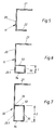
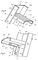
- the first embodiment which comprises three design variants belonging to a ladder program, is shown in FIGS. 1 to 7 and is initially dealt with in a coherent manner with the basic points of variation.
- a ladder 10 consists of two spars 11 and broad rungs 12 attached therebetween.
- the broad rungs 12 have a C profile which is open at the bottom and has an entrance wall 13, a front leg 14 and a rear leg 15. They are made from extruded aluminum -Profil or from folded sheet metal profile made of light metal or galvanized steel sheet or the like.
- the upper tread surface 16 is equipped with anti-slip ribs 17. On the trailing edge 18, a raised tip or other profiling, not yet shown, can be provided.
- the tread depth T of the broad rungs 12 is at least 35 mm, but preferably approximately 40-50 mm. As a result, they ensure a secure stand and, above all, satisfy the special purpose that wide rungs 12 of the same profile can always be used with a wide variety of ladders with different spars and different lengths.
- the spars 11 here consist of an inwardly open C-profile with an outer web 20, a front leg 21 and a rear leg 22. These can either be the same width or it can be useful - as can be seen in FIG. 5 - the rear leg 22 should be somewhat wider, so that the larger amount of material runs in the pull zone and the forces are absorbed cheaply.
- Such a simple C-profile for ladder stiles is known per se. It is also known to interpose levels. However, the aim here is to show, in the context of the optimization of a modular production, that the same broad rungs can also be used in such known, simple C-profile spars that are open inwards.
- the previously known C-profiles have the same front leg and rear leg. According to the invention, the rear leg can advantageously be equipped with a larger material cross section.
- the steps are expediently fastened by rivets 23 which are guided in a known manner through the legs of spars and broad rungs.
- stiffening angle 25 which has two legs 24.1 and 24.2. These have a width that is less than the height or width of the front leg 14. They are of a suitable length.
- the horizontal legs 24. 1 are covered by the front legs 14 and protrude beyond the front legs 21, so that there is still a rivet point 26 which does not extend through the cross-section of the spar, but extends the length of the holding lever.
- Another rivet point 27 is only in the front leg 21 of the spar profile and also offers one here Good support base for the vertical leg 24.2 of the stiffening angle 25, which projects downward in the spar.
- the rivet in the corner point 28 connects the spar 11, wide rung 12 and stiffening angle 25.
- connection between spars, wide rungs and stiffening angles can be made with a few rivet points.
- stiffening angle on the one hand, is easy to produce because of its flat, simply punched-out design and, on the other hand, has great stability and that the riveting does not result in any heat loads on the profiles which may be made of light metal, which would reduce their strength.
- the rivet connection can be made inexpensively in large numbers. Bracing angles need not be used in every step. Depending on the length of the ladder, they are to be distributed over the length.
- point-like joint connections such as screws
- spot-weld connections or the like can be used.
- a particularly advantageous possibility for the point-like connection of the materials to be processed for conductors, such as rolled or bent steel profiles or extruded light metal profiles, consists in the use of clinching connections. Suitable matrices and stamps are used to press the material of one flat part into a recess in the immediately adjacent other part, so that the components are positively connected to one another by permanent deformation of their materials.
- connections can be used like conventional riveted connections at the locations designated by 23, 26, 27, 28, 28.1, 28.2 and indicated by dots.
- the same or similar materials with very related material properties such as light metal bars and light metal rungs, will preferably be connected to one another by means of clinching connections.
- steel and light metal can also be connected to one another with suitable design of the clinching connections with regard to dimensions and tools.
- the rear leg is designed here according to the invention in a special embodiment as a box profile 32 so that the web 20 has a web box wall 20.1 in a linear extension and the rear leg is formed with a rung contact wall 33 which is the rear leg 22 of the first ladder configuration with regard to the installation and fastening of the broad rung, but not only with regard to the load capacity.
- An outer wall 34 lies at a distance A 2 from the rung contact wall 33 shown in FIG. 7. Both are connected via the inner wall 35. It can this box section 32 can be formed by folding alone, by folding and welding together in the corner 36 or as a light metal extrusion profile.
- the ladder can be optimized considerably with regard to the use of material, weight and use.
- FIGS. 8 to 17 corresponds in its basic structure to the first embodiment with its design variants. Accordingly, the same parts are provided with the same reference numerals. Only the shape of the profiles is slightly varied, both with regard to the dimensions as well as the edge designs and corner designs. Only these deviations are described below.
- the cross section of the spars 11.1 always has the same width of the front leg 21 and the rear leg 22.
- partially cylindrical corner ribs 40.1 to 40.4 are provided on all longitudinal edges of the spars 11. On the one hand, these improve stability and make the profile more comfortable to hold. To a certain extent, they also prevent scratching smooth surfaces when they are placed against one another and the like.
- the wide rungs 12.1 are shown in FIGS. 8 to 11 with relatively low front leg 14.1 and rear leg 15.1. They have partially cylindrical reinforcing ribs 45 on their lower edges.
- both the tread surface 16 is arched upwards and has the anti-slip ribs 17 and on the rear edge 46 a clearly protruding pointed rib 47, while the front tread edge 48 is slightly rounded. This means that when you step with your foot, you notice which side of the broad rung you are standing on and whether the ladder is placed the wrong way round.
- reinforcement legs 50.1 and 50.2 can be provided on the lower edges of front leg 14.1 and rear leg 15.1. 16 have a relatively small width and increase the section modulus accordingly.
- the reinforcement angles 50.3 and 50.4 are designed with a greater width, so that the section modulus is increased accordingly without the step space would be hindered. This allows you to produce wider rungs with an otherwise slim profile. All of these profile parts are made of extruded aluminum profile and are only cut, joined and riveted. They can also be at least partially welded.
- Fig. 18 shows an entire ladder in which the profile parts described above are used.
- Other conductor shapes can also be formed in the manner according to the invention.
- a ladder (10) has bars (11) and broad rungs (12).
- the wide rungs (12) are designed as C-profiles which are open at the bottom and have a non-slip tread (16).
- the spars (11) have either a simple, appropriately dimensioned leg in the tension zone or a box profile which increases the section modulus.
- the same broad rungs (12) can be used for differently designed ladders.
Landscapes
- Engineering & Computer Science (AREA)
- Mechanical Engineering (AREA)
- Ladders (AREA)
- Inorganic Insulating Materials (AREA)
- Photoreceptors In Electrophotography (AREA)
- Transition And Organic Metals Composition Catalysts For Addition Polymerization (AREA)
- Infusion, Injection, And Reservoir Apparatuses (AREA)
- Electrical Discharge Machining, Electrochemical Machining, And Combined Machining (AREA)
Claims (17)
- Système d'unités de montage pour l'assemblage d'échelles (10) dont les montants (11; 11.1) et les barreaux (12; 12.1) sont formés par des profilés en métal à paroi mince qui sont assemblés par rivetage, soudure ou similaire, le profilé de montant présentant une joue (20) située à l'extérieur, un côté antérieur (21) et un côté postérieur (22) formant une pièce avec celle-ci, orientés en direction de l'autre montant, les barreaux étant réalisé comme des barreaux larges (12; 12.1 ) à profil couché en C, de même taille pour différentes échelles, avec une profondeur de marche (T) d'au moins 45 mm, dont les pans antérieurs (14; 14.1) sont directement adjacents aux parois intérieures des côtés antérieurs (21) des montants (11; 11.1), les côtés antérieurs étant les mêmes pour des échelles différentes, et l'écartement entre les côtés antérieurs (21) et les côtés postérieurs (22) ou, le cas échéant, entre le côté antérieur (21) et une paroi de montage (33) pour les barreaux réalisée sur la joue (20) des barreaux, correspondant à la largeur des barreaux (12), et les côtés postérieurs (22; 32) des montants (11; 11.1.) présentant une configuration et/ou dimension de section répondant aux conditions de sollicitations en direction de l'axe des montants et aux besoins de solidité correspondants d'échelles (10) de différentes longueurs et pour différentes charges.
- Echelle assemblée avec un système d'unités de montage d'échelles selon la revendication 1, caractérisée en ce que les barreaux larges (12; 12.1) sont disposés de manière excentrique dans les montants (11; 11.1) et en ce que leurs zones sous tension (22, 32) sont renforcées.
- Echelle assemblée avec un système d'unités de montage d'échelles selon la revendication 1 ou 2 caractérisée en ce que les zones sous tension des montants (11; 11.1) sont formées par des profilés cintrés et/ou repliés qui ont la forme de caissons.
- Echelle assemblée avec un système d'unités de montage d'échelles selon la revendication 3, caractérisée en ce que le profit en caisson (32) est un profit rectangulaire.
- Echelle assemblée avec un système d'unités de montage d'échelles selon la revendication 4, caractérisée en ce que le profit eu caisson rectangulaire formé dans les zones sous tension des montants (11; 11.1) présente une paroi de caisson de jolie (20.1) située en prolongement de la joue (20), une paroi intérieure (35) décalée en écartement vers l'intérieur et une paroi de montage (33) pour les barreaux, perpendiculairement adjacente à la paroi de caisson, et une paroi extérieure (34) qui s'étend parallèlement et à distance (A1; A2) de celle-ci.
- Echelle assemblée avec un système d'unités de montage d'échelles selon les revendications 1 ou 2, caractérisée en ce que les côtés postérieurs (22) des montants (11) situés dans les zones sous tension sont plus larges que les côtés antérieurs (21).
- Echelle assemblée avec un système d'unités de montage d'échelles selon l'une au moins des revendications 1 à 6, caractérisée en ce que les arêtes des montants (11.1) sont pourvues de nervures d'angle de préférence partiellement cylindriques (40.1 à 40.4)
- Echelle assemblée avec un système d'unités de montage d'échelles selon la revendication 1 à 7, caractérisée en ce que les surfaces d'appui (16) des barreaux larges (12.1) sont réalisées légèrement bombées vers le haut, de préférence partiellement cylindriques avec des nervures antidérapantes (17).
- Echelle assemblée avec un système d'unités de montage d'échelles selon la revendication 1 a 8, caractérisée en ce que des nervures de renforcement (45) ou des ailes de renforcement (50.1 à 50.4) dirigées vers l'intérieur sont réalisées sur les arêtes inférieures des pans verticaux (14.1; 15.1) des barreaux larges (12.1).
- Echelle assemblée avec un système d'unités de montage d'échelles selon la revendication 1 à 9, caractérisée en ce que les pans postérieurs (15) des barreaux larges (12; 12.1) sont plus hauts que les pans antérieurs (14).
- Echelle assemblée avec un système d'unités de montage d'échelles selon la revendication 1 à 10, caractérisée en ce que le profilage des surfaces d'appui (16) des barreaux larges (2.1) est saillant (47) dans la zone postérieure de manière à être perçu
en posant le pied. - Echelle assemblée avec un système d'unités de montage d'échelles selon la revendication 11, caractérisée en ce qu'une pointe (47) est formée sur l'arête postérieure (46) de la surface d'appui (16) du barreau large (12.1).
- Echelle assemblée avec un système d'unités de montage d'échelles selon l'une au moins des revendications 1 à 12, caractérisée en ce que les montants (11; 11.1) et/ou les barreaux larges (12; 12.1) sont formés en profilés extrudés de métal léger.
- Echelle assemblée avec un système d'unités de montage d'échelles selon l'une au moins des revendications 1 à 12, caractérisée en ce que les montants (11; 11.1) et/ou les barreaux larges (12; 12.1) sont formés en pièces de tôle d'acier et/ou en pièces de tôle de métal léger, protégées contre la corrosion.
- Echelle assemblée avec un système d'unités de montage d'échelles selon l'une au moins des revendications 1 à 14, caractérisée en ce que les montants (11; 11.1) et les barreaux larges (12; 12.1) sont assemblés aux points d'assemblage (23, 26, 27, 28, 28.1, 28.2) au moyen d'assemblages rivetés.
- Echelle assemblée avec un système d'unités de montage d'échelles selon l'une au moins des revendications 1 à 15, caractérisée en ce qu'au moins dans des coins individuels de l'échelle entre les montants (11; 11.1) et les barreaux larges (12; 12.1) il est prévu des équerres de renforcement (25) dont la largeur des bras correspond à la largeur intérieure des pans des barreaux larges (12; 12.1) dans lesquels ils sont montés et en ce que les équerres de renforcement (25) sont fixées aux barreaux larges (12; 12.1) et aux montants (11; 11.1) par assemblage angulaire stable, de préférence par rivetage.
- Echelle assemblée avec un système d'unités de montage d'échelles selon la revendication 16, caractérisée en ce que les équerres de renforcement (25) sont réalisées sous forme de pièces en équerre plates à la manière des équerres de fenêtre.
Priority Applications (1)
| Application Number | Priority Date | Filing Date | Title |
|---|---|---|---|
| AT89103466T ATE97192T1 (de) | 1988-03-02 | 1989-02-28 | Leiter. |
Applications Claiming Priority (2)
| Application Number | Priority Date | Filing Date | Title |
|---|---|---|---|
| DE3806668A DE3806668A1 (de) | 1988-03-02 | 1988-03-02 | Leiter |
| DE3806668 | 1988-03-02 |
Publications (2)
| Publication Number | Publication Date |
|---|---|
| EP0331098A1 EP0331098A1 (fr) | 1989-09-06 |
| EP0331098B1 true EP0331098B1 (fr) | 1993-11-10 |
Family
ID=6348589
Family Applications (1)
| Application Number | Title | Priority Date | Filing Date |
|---|---|---|---|
| EP89103466A Expired - Lifetime EP0331098B1 (fr) | 1988-03-02 | 1989-02-28 | Echelle |
Country Status (7)
| Country | Link |
|---|---|
| EP (1) | EP0331098B1 (fr) |
| AT (1) | ATE97192T1 (fr) |
| DE (2) | DE3806668A1 (fr) |
| DK (1) | DK97789A (fr) |
| FI (1) | FI890993A7 (fr) |
| NO (1) | NO890879L (fr) |
| PT (1) | PT89881A (fr) |
Families Citing this family (3)
| Publication number | Priority date | Publication date | Assignee | Title |
|---|---|---|---|---|
| FR2701512B1 (fr) * | 1993-02-16 | 1995-05-12 | Tubesca | Procédé et dispositif de fixation d'accessoires pour échelles. |
| NZ272517A (en) * | 1994-07-08 | 1998-05-27 | Werner Co | Ladder support bracket, second portion conforms with and extends along the rail to which it is attached |
| DE20106086U1 (de) * | 2001-04-06 | 2001-06-13 | Zarges GmbH & Co. KG, 82362 Weilheim | Leiter |
Family Cites Families (12)
| Publication number | Priority date | Publication date | Assignee | Title |
|---|---|---|---|---|
| DE7438125U (de) * | 1975-06-05 | Ernst Sebastian | Leiter aus Metall | |
| DE7301574U (de) * | 1973-05-10 | Nissen H | Steh- und Anlegeleiter mit eingenieteten Sprossen | |
| DE7240786U (de) * | 1973-02-15 | Schneider F | Metallsprossenleiter | |
| DE7312308U (de) * | 1973-10-04 | Schneider F | Metalleiter, insbesondere Aluminiumleiter | |
| US1595952A (en) * | 1925-07-21 | 1926-08-10 | Kramer Bissell Company Inc | Brace |
| DE1768014U (de) * | 1958-03-19 | 1958-06-04 | Zarges Leichtmetallbau K G | Aus profilstaeben gebildete stufen, insbesondere fuer leitern. |
| US3181651A (en) * | 1961-05-09 | 1965-05-04 | White Metal Rolling & Stamping | Ladder and rung connection |
| DE7128163U (de) * | 1971-07-22 | 1971-10-28 | Fuchs O | Stufenleiter |
| FR2356801A1 (fr) * | 1976-07-01 | 1978-01-27 | Genries Pierre | Nouvel assemblage d'echelons et/ou echelons et marches metalliques sur les montants d'echelles |
| DE7737792U1 (de) * | 1977-12-10 | 1979-05-17 | Bernhard Himmelsbach, Leitern- U. Holzwarenfabrik, Inh. Josef Federle, 7832 Kenzingen | Aluminium-sprossen-profil |
| US4655320A (en) * | 1984-12-14 | 1987-04-07 | Benboid Pty Ltd. | Ladder means and method of production |
| US4716988A (en) * | 1986-08-06 | 1988-01-05 | Top Line Manufacturing Inc. | Ladder step construction for use with recreational vehicles and boats |
-
1988
- 1988-03-02 DE DE3806668A patent/DE3806668A1/de not_active Withdrawn
-
1989
- 1989-02-28 EP EP89103466A patent/EP0331098B1/fr not_active Expired - Lifetime
- 1989-02-28 AT AT89103466T patent/ATE97192T1/de active
- 1989-02-28 DE DE89103466T patent/DE58906126D1/de not_active Expired - Fee Related
- 1989-03-01 DK DK097789A patent/DK97789A/da not_active Application Discontinuation
- 1989-03-01 NO NO89890879A patent/NO890879L/no unknown
- 1989-03-01 PT PT89881A patent/PT89881A/pt not_active Application Discontinuation
- 1989-03-02 FI FI890993A patent/FI890993A7/fi not_active Application Discontinuation
Also Published As
| Publication number | Publication date |
|---|---|
| DK97789D0 (da) | 1989-03-01 |
| DK97789A (da) | 1989-09-03 |
| NO890879D0 (no) | 1989-03-01 |
| PT89881A (pt) | 1989-11-10 |
| DE3806668A1 (de) | 1989-09-14 |
| NO890879L (no) | 1989-09-04 |
| FI890993L (fi) | 1989-09-03 |
| FI890993A0 (fi) | 1989-03-02 |
| FI890993A7 (fi) | 1989-09-03 |
| EP0331098A1 (fr) | 1989-09-06 |
| DE58906126D1 (de) | 1993-12-16 |
| ATE97192T1 (de) | 1993-11-15 |
Similar Documents
| Publication | Publication Date | Title |
|---|---|---|
| EP0864489B1 (fr) | Elément de plancher | |
| DE2916826C2 (fr) | ||
| EP0300399A2 (fr) | Plateforme d'échafaudage composé de profilés extrudés en métal léger | |
| DE19612867A1 (de) | Gerüstboden | |
| EP3765685B1 (fr) | Escalier d'échafaudage comprenant des supports de marche | |
| EP1737778A2 (fr) | Escalier roulant ou trottoir roulant | |
| EP0331098B1 (fr) | Echelle | |
| DE3539507A1 (de) | Geruestrahmentafel | |
| DE19806092A1 (de) | Gerüstboden | |
| DE10012685B4 (de) | Verfahren zur Herstellung eines Laufbodens | |
| CH675142A5 (fr) | ||
| DE8502756U1 (de) | Gerüstrahmentafel | |
| EP0451616B1 (fr) | Plate-forme d'échafaudage | |
| EP0606557A1 (fr) | Balustrade à fixer sur des parois latérales | |
| DE102010019569A1 (de) | Treppenleiter mit Treppenstufen | |
| DE202005017755U1 (de) | Transportwagen und Schrank | |
| EP0451617A1 (fr) | Crochet de support pour plate-forme d'échafaudage | |
| EP0736648A1 (fr) | Echafaudage | |
| EP1162329A1 (fr) | Connexion entre montant et échelons pour éléments d'échafaudages ou similaires | |
| DE4418905A1 (de) | Laufboden für Gerüste | |
| DE3602331A1 (de) | Leiter | |
| DE19922254B4 (de) | Lichtschachtanordnung | |
| DE102004008186B4 (de) | Sperrholz-Metall-Platten-Verbund-Boden | |
| DE4311788A1 (de) | Lauf- und Arbeitsflächen-Element | |
| DE1434934C (de) | Dreiteilige Ausziehleiter |
Legal Events
| Date | Code | Title | Description |
|---|---|---|---|
| PUAI | Public reference made under article 153(3) epc to a published international application that has entered the european phase |
Free format text: ORIGINAL CODE: 0009012 |
|
| AK | Designated contracting states |
Kind code of ref document: A1 Designated state(s): AT BE CH DE ES FR GB GR IT LI LU NL SE |
|
| 17P | Request for examination filed |
Effective date: 19891026 |
|
| 17Q | First examination report despatched |
Effective date: 19901122 |
|
| GRAA | (expected) grant |
Free format text: ORIGINAL CODE: 0009210 |
|
| AK | Designated contracting states |
Kind code of ref document: B1 Designated state(s): AT BE CH DE ES FR GB GR IT LI LU NL SE |
|
| PG25 | Lapsed in a contracting state [announced via postgrant information from national office to epo] |
Ref country code: IT Free format text: LAPSE BECAUSE OF FAILURE TO SUBMIT A TRANSLATION OF THE DESCRIPTION OR TO PAY THE FEE WITHIN THE PRE;WARNING: LAPSES OF ITALIAN PATENTS WITH EFFECTIVE DATE BEFORE 2007 MAY HAVE OCCURRED AT ANY TIME BEFORE 2007. THE CORRECT EFFECTIVE DATE MAY BE DIFFERENT FROM THE ONE RECORDED.SCRIBED TIME-LIMIT Effective date: 19931110 Ref country code: GR Free format text: LAPSE BECAUSE OF FAILURE TO SUBMIT A TRANSLATION OF THE DESCRIPTION OR TO PAY THE FEE WITHIN THE PRESCRIBED TIME-LIMIT Effective date: 19931110 Ref country code: GB Effective date: 19931110 Ref country code: SE Effective date: 19931110 Ref country code: NL Effective date: 19931110 Ref country code: BE Effective date: 19931110 Ref country code: ES Free format text: THE PATENT HAS BEEN ANNULLED BY A DECISION OF A NATIONAL AUTHORITY Effective date: 19931110 Ref country code: FR Effective date: 19931110 |
|
| REF | Corresponds to: |
Ref document number: 97192 Country of ref document: AT Date of ref document: 19931115 Kind code of ref document: T |
|
| REF | Corresponds to: |
Ref document number: 58906126 Country of ref document: DE Date of ref document: 19931216 |
|
| PG25 | Lapsed in a contracting state [announced via postgrant information from national office to epo] |
Ref country code: CH Effective date: 19940228 Ref country code: LI Effective date: 19940228 Ref country code: LU Free format text: LAPSE BECAUSE OF NON-PAYMENT OF DUE FEES Effective date: 19940228 Ref country code: AT Effective date: 19940228 |
|
| EN | Fr: translation not filed | ||
| NLV1 | Nl: lapsed or annulled due to failure to fulfill the requirements of art. 29p and 29m of the patents act | ||
| GBV | Gb: ep patent (uk) treated as always having been void in accordance with gb section 77(7)/1977 [no translation filed] |
Effective date: 19931110 |
|
| PLBE | No opposition filed within time limit |
Free format text: ORIGINAL CODE: 0009261 |
|
| STAA | Information on the status of an ep patent application or granted ep patent |
Free format text: STATUS: NO OPPOSITION FILED WITHIN TIME LIMIT |
|
| REG | Reference to a national code |
Ref country code: CH Ref legal event code: PL |
|
| PG25 | Lapsed in a contracting state [announced via postgrant information from national office to epo] |
Ref country code: DE Effective date: 19941101 |
|
| 26N | No opposition filed |