EP0331101A2 - Suspension strut for cranes - Google Patents
Suspension strut for cranes Download PDFInfo
- Publication number
- EP0331101A2 EP0331101A2 EP89103476A EP89103476A EP0331101A2 EP 0331101 A2 EP0331101 A2 EP 0331101A2 EP 89103476 A EP89103476 A EP 89103476A EP 89103476 A EP89103476 A EP 89103476A EP 0331101 A2 EP0331101 A2 EP 0331101A2
- Authority
- EP
- European Patent Office
- Prior art keywords
- support element
- guide housing
- hydraulic cylinder
- piston
- hydraulic
- Prior art date
- Legal status (The legal status is an assumption and is not a legal conclusion. Google has not performed a legal analysis and makes no representation as to the accuracy of the status listed.)
- Granted
Links
- 239000000725 suspension Substances 0.000 title description 3
- 239000006096 absorbing agent Substances 0.000 description 3
- 230000035939 shock Effects 0.000 description 3
- 229910000906 Bronze Inorganic materials 0.000 description 1
- 238000005452 bending Methods 0.000 description 1
- 239000010974 bronze Substances 0.000 description 1
- KUNSUQLRTQLHQQ-UHFFFAOYSA-N copper tin Chemical compound [Cu].[Sn] KUNSUQLRTQLHQQ-UHFFFAOYSA-N 0.000 description 1
- 230000007547 defect Effects 0.000 description 1
- 238000011161 development Methods 0.000 description 1
- 230000018109 developmental process Effects 0.000 description 1
- 239000013589 supplement Substances 0.000 description 1
Images


Classifications
-
- B—PERFORMING OPERATIONS; TRANSPORTING
- B60—VEHICLES IN GENERAL
- B60G—VEHICLE SUSPENSION ARRANGEMENTS
- B60G11/00—Resilient suspensions characterised by arrangement, location or kind of springs
- B60G11/26—Resilient suspensions characterised by arrangement, location or kind of springs having fluid springs only, e.g. hydropneumatic springs
-
- B—PERFORMING OPERATIONS; TRANSPORTING
- B60—VEHICLES IN GENERAL
- B60G—VEHICLE SUSPENSION ARRANGEMENTS
- B60G17/00—Resilient suspensions having means for adjusting the spring or vibration-damper characteristics, for regulating the distance between a supporting surface and a sprung part of vehicle or for locking suspension during use to meet varying vehicular or surface conditions, e.g. due to speed or load
- B60G17/02—Spring characteristics, e.g. mechanical springs and mechanical adjusting means
- B60G17/04—Spring characteristics, e.g. mechanical springs and mechanical adjusting means fluid spring characteristics
-
- B—PERFORMING OPERATIONS; TRANSPORTING
- B60—VEHICLES IN GENERAL
- B60G—VEHICLE SUSPENSION ARRANGEMENTS
- B60G2300/00—Indexing codes relating to the type of vehicle
- B60G2300/06—Cranes
Definitions
- the invention relates to a suspension strut with an outer guide housing arranged on the frame of a crane vehicle and an axially and rotationally movable support element relative to this, a hydraulic pressure chamber being present between the guide housing and the support element.
- Shock absorbers are known on dump trucks in which an outer guide housing is designed as a hydraulic cylinder closed at the top. A piston is slidably guided in this hydraulic cylinder, the relatively strong piston rod of which is hydraulically "open” in the lower, i.e. hydraulically unloaded part is mechanically guided. At the free end of the piston rod serving as an axially displaceable support element, a flange is arranged to which the wheel suspension is attached.
- the object of the invention is therefore to create a shock absorber in which the disadvantages mentioned are avoided with simple means.
- This object is achieved in that the pressure chamber is formed by a hydraulic cylinder arranged within the support element and is closed by an axially and rotationally fixed piston connected to the guide housing.
- the piston Since the piston must be smaller than the outer diameter of the guide element, there is a relatively small piston area compared to the prior art, so that - albeit with a higher pressure - displaces a smaller amount of hydraulic medium with the same relative movement between the support element and the guide housing must become.
- Claim 2 specifies a particularly simple and therefore robust embodiment of a shock absorber.
- the hydraulic cylinder can be easily replaced in the event of a defect and replaced by a new one.
- a strut 2 is arranged on the vehicle frame 1 of a road crane.
- This consists of a hollow cylindrical guide housing 3 fastened to the vehicle frame 1, in which a cylindrical support element 4 is slidably and rotatably guided.
- ring-shaped guide elements 5 in the guide housing 3 made of e.g. Bronze or plastic provided.
- the support element 4 is provided at its outer end with a flange 6, on which a so-called knuckle bell or a wheel carrier 7 for receiving one of the wheels 8 of the crane is attached.
- a steering lever 9 is attached to the flange 6, which is connected to a steering linkage, not shown.
- the support element 4 is formed on the inside as a hollow cylinder 10, in which a piston 11 is located.
- the piston rod 12 of the piston 11 faces away from the flange 6 and is firmly connected to the cover or base 13 fastened to the closed end of the guide housing 3, ie immovably and rotationally arranged against the guide housing 3.
- the cylinder chamber 14 located between the flange 6 and the piston 11 represents a self-contained pressure chamber of the hydraulic cylinder 10 or the spring strut 2 and is connected via a bore 15 through the piston 11 and the piston rod 12 and a line 16 to a hydraulic or pressure accumulator 17 connected.
- the piston rod 12 is penetrated by a further bore 18, which is connected on the one hand to the cylinder chamber 24 above the piston 11 and on the other hand is connected to another supply line or alternatively to the pressure accumulator 17 or - to block the relative movement of the support element 4 with respect to the guide housing 3 or the piston 11 - can be connected directly to the lower cylinder chamber 14 by switching off the pressure accumulator 17.
- the hydraulic pressure in the pressure chamber 14 is substantially equal to the pressure set in the pressure accumulator 17.
- the guide housing 3 pushes further onto the support element 4 or dips the support element 4 deeper into the housing 3, as a result of which the pressure space 14 is reduced .
- hydraulic medium is partially displaced from the pressure chamber 14 through the bore 15 in the direction of the pressure accumulator 17, in which the hydraulic pressure rises accordingly in relation to the set pressure, so that the relative movement between the support element 4 and the guide housing 3 is limited within the hydraulic balance becomes.
- an adjustable throttle 19 is installed in the line 16 leading to the pressure accumulator 17.
- the cylinder chamber 24 located above the piston 11 is pressurized and the cylinder chamber 14 is depressurized.
- the guide housing 103 is essentially unchanged.
- the support element 104 is formed in two parts and has an outer guide tube 120 and a hydraulic cylinder 121 located therein, the guide tube 120 and the hydraulic cylinder 121 being releasably connected to one another.
- the piston 111 is located within the hydraulic cylinder 121.
- the individual parts of the spring strut 102 which are not described further, have a reference number 100 higher in the drawing than the exemplary embodiment according to FIG. 1 (for example guide element 105 instead of 5 ).
Landscapes
- Engineering & Computer Science (AREA)
- Mechanical Engineering (AREA)
- Vehicle Body Suspensions (AREA)
- Fluid-Damping Devices (AREA)
Abstract
Dieses Federbein ist an einem Fahrzeugrahmen (1) angeordnet und weist ein äußeres Führungsgehäuse (3; 103) und ein axial und rotatorisch relativ zu diesem bewegbares Stützelement (4; 104) auf. Zwischen dem Führungsgehäuse (3; 103) und dem Stützelement (4; 104) ist ein hydraulischer Druckraum (14; 114) vorhanden. Dieser Druckraum (14; 114) ist durch einen innerhalb des Stützelements (4; 104) angeordneten Hydraulikzylinder (10; 110) gebildet und durch einen axial und rotatorisch fest mit dem Führungsgehäuse (3; 103) verbundenen Kolben (11; 111) verschlossen.This spring strut is arranged on a vehicle frame (1) and has an outer guide housing (3; 103) and a support element (4; 104) which can be moved axially and rotationally relative to the latter. A hydraulic pressure chamber (14; 114) is present between the guide housing (3; 103) and the support element (4; 104). This pressure chamber (14; 114) is formed by a hydraulic cylinder (10; 110) arranged within the support element (4; 104) and closed by a piston (11; 111) which is axially and rotationally fixed to the guide housing (3; 103).
Der Hydraulikzylinder (10; 110) kann durch das Stützelement (4) selbst gebildet oder als separate Einheit (121) in das Stützelement (104, 120) eingesetzt sein. 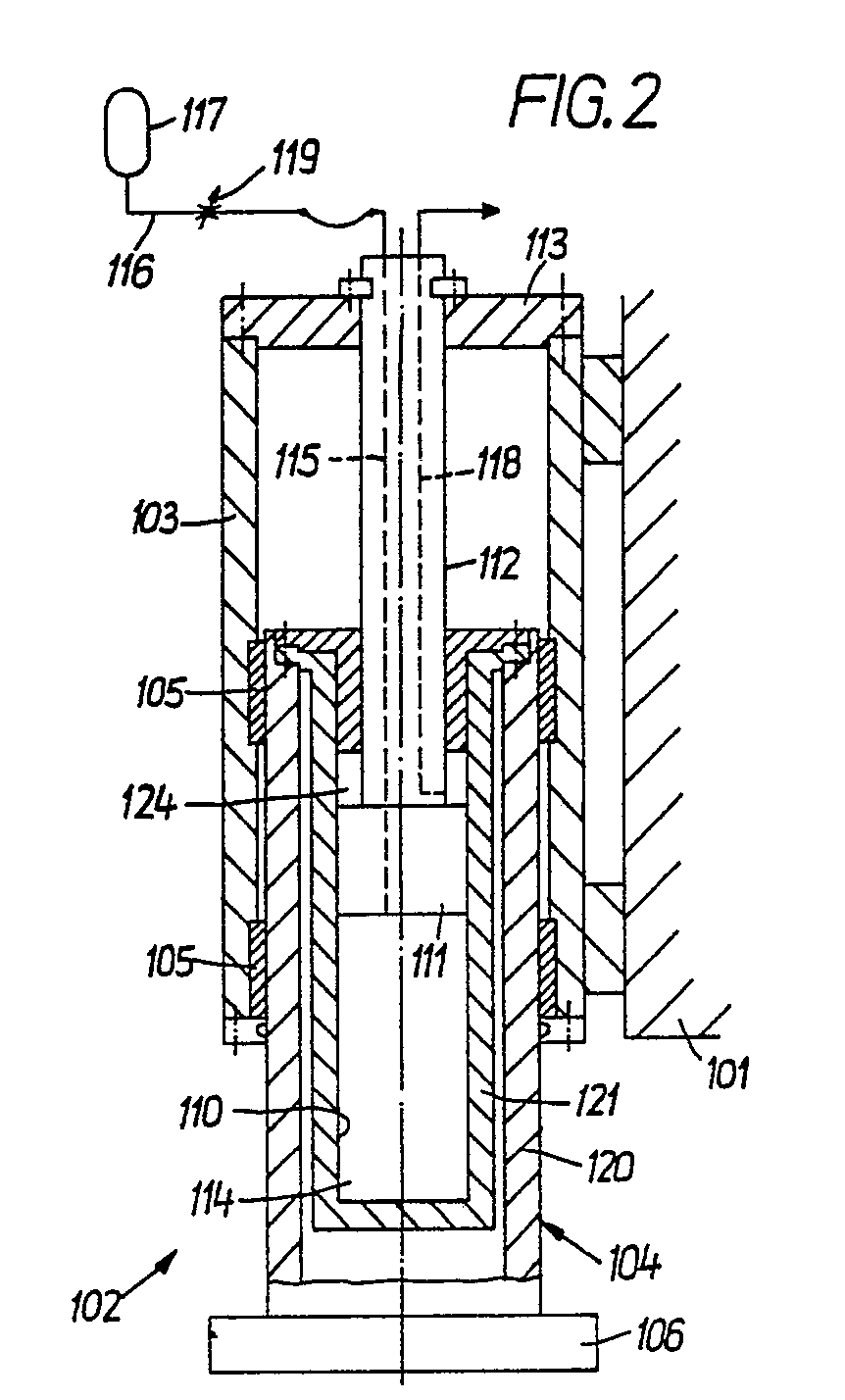
Description
Die Erfindung betrifft ein Federbein mit einem an dem Rahmen eines Kranfahrzeugs angeordneten äußeren Führungsgehäuse und einem axial und rotatorisch relativ zu diesem bewegbaren Stützelement, wobei zwischen dem Führungsgehäuse und dem Stützelement ein hydraulischer Druckraum vorhanden ist.The invention relates to a suspension strut with an outer guide housing arranged on the frame of a crane vehicle and an axially and rotationally movable support element relative to this, a hydraulic pressure chamber being present between the guide housing and the support element.
An Muldenkippern sind Federbeine bekannt, bei denen ein äußeres Führungsgehäuse als oben geschlossener Hydraulikzylinder ausgebildet ist. In diesem Hydraulikzylinder ist ein Kolben gleitend geführt, dessen relativ starke Kolbenstange im unteren, hydraulisch "offenen", d.h. hydraulisch nicht beanspruchten Teil mechanisch geführt ist. An dem freien Ende der als axial verschiebbares Stützelement dienenden Kolbenstange ist ein Flansch angeordnet, an dem die Radaufhängung befestigt ist.Shock absorbers are known on dump trucks in which an outer guide housing is designed as a hydraulic cylinder closed at the top. A piston is slidably guided in this hydraulic cylinder, the relatively strong piston rod of which is hydraulically "open" in the lower, i.e. hydraulically unloaded part is mechanically guided. At the free end of the piston rod serving as an axially displaceable support element, a flange is arranged to which the wheel suspension is attached.
Bei großen Querkräften, wie sie z.B. beim Bremsen oder beim Fahren über ein Hindernis auftreten, erfährt die Kolbenstange ein Biegemoment, das den Kolben aus seiner axialen Ausrichtung zu bringen versucht. Dabei kann es zu Verkantungen des Kolbens, die sein Gleiten innerhalb des Zylinders erschweren, und zu erhöhten Leckverlusten kommen.With large transverse forces, such as occur when braking or driving over an obstacle, the piston rod experiences a bending moment that tries to bring the piston out of its axial orientation. This can cause the piston to tilt, which makes it difficult to slide inside the cylinder, and can lead to increased leakage losses.
Der Erfindung liegt deshalb die Aufgabe zugrunde, ein Federbein zu schaffen, bei dem die erwähnten Nachteile mit einfachen Mitteln vermieden werden. Diese Aufgabe wird erfindungsgemäß dadurch gelöst, daß der Druckraum durch einen innerhalb des Stützelements angeordneten Hydraulikzylinder gebildet und durch einen axial und rotatorisch fest mit dem Führungsgehäuse verbundenen Kolben verschlossen ist.The object of the invention is therefore to create a shock absorber in which the disadvantages mentioned are avoided with simple means. This object is achieved in that the pressure chamber is formed by a hydraulic cylinder arranged within the support element and is closed by an axially and rotationally fixed piston connected to the guide housing.
Da der hydraulische Druck nunmehr ausschließlich im Innern des Stützelements aufgebracht wird, ergeben sich beim Führungsgehäuse keine Probleme mit Leckverlusten.Since the hydraulic pressure is now only applied inside the support element, there are no problems with leakage losses in the guide housing.
Da der Kolben kleiner sein muß als der Außendurchmesser des Führungselements ergibt sich gegenüber dem Stand der Technik eine verhältnismäßig kleine Kolbenfläche, so daß - wenn auch unter Inkaufnahme von einem höheren Druck - bei gleicher Relativbewegung zwischen dem Stützelement und dem Führungsgehäuse eine geringere Menge an Hydraulikmedium verdrängt werden muß.Since the piston must be smaller than the outer diameter of the guide element, there is a relatively small piston area compared to the prior art, so that - albeit with a higher pressure - displaces a smaller amount of hydraulic medium with the same relative movement between the support element and the guide housing must become.
Vorteilhafte Weiterbildungen der Erfindung sind in den Unteransprüchen beschrieben. So gibt der Anspruch 2 eine besonders einfache und damit robuste Ausführungsform eines Federbeins an. Beim Anspruch 3 ergibt sich der besondere Vorteil, daß der Hydraulikzylinder im Fall eines Defekts einfach ausgewechselt und durch einen neuen ersetzt werden kann.Advantageous developments of the invention are described in the subclaims.
Ausführungsbeispiele des Gegenstandes der Erfindung sind in der Zeichnung teilweise schematisch dargestellt und werden im folgenden näher erläutert.Exemplary embodiments of the object of the invention are shown schematically in the drawing and are explained in more detail below.
Es zeigen:
- Fig. 1 ein an einem Kranfahrgestell befestigtes Federbein im Längsschnitt und
- Fig. 2 ein anderes Ausführungsbeispiel eines Federbeins im Längsschnitt.
- Fig. 1 a strut attached to a crane chassis in longitudinal section and
- Fig. 2 shows another embodiment of a strut in longitudinal section.
Bei dem Ausführungsbeispiel gemäß Fig. 1 ist an dem Fahrzeugrahmen 1 eines Straßenkrans ein Federbein 2 angeordnet. Dieses besteht aus einem an dem Fahrzeugrahmen 1 befestigten hohlzylindrischen Führungsgehäuse 3, in dem ein zylindrisches Stützelement 4 gleit- und drehbar geführt ist. Zum Übertragen von z.B. durch Bremsen hervorgerufene Querkräfte sind ringförmige Führungselemente 5 in dem Führungsgehäuse 3 aus z.B. Bronze oder Kunststoff vorgesehen.In the embodiment shown in FIG. 1, a
Das Stützelement 4 ist an seinem äußeren Ende mit einem Flansch 6 versehen, an dem eine sog. Achsschenkelglocke oder ein Radträger 7 zur Aufnahme eines der Räder 8 des Krans befestigt ist. Außerdem ist an dem Flansch 6 ein Lenkhebel 9 befestigt, der mit einem nicht näher dargestellten Lenkgestänge verbunden ist. Das Stützelement 4 ist innen als Hohlzylinder 10 ausgebildet, in dem sich ein Kolben 11 befindet. Die Kolbenstange 12 des Kolbens 11 weist von dem Flansch 6 weg und ist mit dem an dem geschlossenen Ende des Führungsgehäuses 3 befestigten Deckel bzw. Boden 13 fest verbunden, d.h. axial und rotatorisch gegen das Führungsgehäuse 3 unbeweglich angeordnet.The support element 4 is provided at its outer end with a flange 6, on which a so-called knuckle bell or a wheel carrier 7 for receiving one of the
Die zwischen dem Flansch 6 und dem Kolben 11 befindliche Zylinderkammer 14 stellt einen in sich geschlossenen Druckraum des Hydraulikzylinders 10 bzw. des Federbeins 2 dar und ist über eine durch den Kolben 11 und die Kolbenstange 12 gehende Bohrung 15 und eine Leitung 16 mit einem Hydro- oder Druckspeicher 17 verbunden. Die Kolbenstange 12 ist von einer weiteren Bohrung 18 durchsetzt, die einerseits mit der Zylinderkammer 24 über dem Kolben 11 verbunden ist und andererseits mit einer anderen Versorgungsleitung oder alternativ mit dem Druckspeicher 17 in Verbindung stehen oder - zum Blockieren der Relativbewegung des Stützelements 4 gegenüber dem Führungsgehäuse 3 bzw. dem Kolben 11 - unter Abschaltung des Druckspeichers 17 unmittelbar mit der unteren Zylinderkammer 14 verbunden sein kann.The cylinder chamber 14 located between the flange 6 and the
Der hydraulische Druck im Druckraum 14 ist im wesentlichen gleich dem im Druckspeicher 17 eingestellten Druck. Bei einer Vergrößerung der Last bzw. bei einem von unten während der Fahrt auf das Rad 2 ausgeübten Stoß schiebt sich das Führungsgehäuse 3 weiter auf das Stützelement 4 auf bzw. taucht das Stützelement 4 tiefer in das Gehäuse 3 ein, wodurch der Druckraum 14 verkleinert wird. Dadurch wird Hydraulikmedium aus dem Druckraum 14 durch die Bohrung 15 teilweise in Richtung auf den Druckspeicher 17 verdrängt, in dem der hydraulische Druck gegenüber dem eingestellten Druck entsprechend ansteigt, so daß die Relativbewegung zwischen dem Stützelement 4 und dem Führungsgehäuse 3 im Rahmen des hydraulischen Gleichgewichts begrenzt wird.The hydraulic pressure in the pressure chamber 14 is substantially equal to the pressure set in the pressure accumulator 17. With an increase in the load or with an impact exerted on the
Um eine stoßartige Relativbewegung zu vermeiden, ist in der zum Druckspeicher 17 führenden Leitung 16 eine einstellbare Drossel 19 eingebaut.In order to avoid a sudden relative movement, an
Zum Anheben des Rades 8 bei abgestütztem Fahrgestell wird die über dem Kolben 11 befindliche Zylinderkammer 24 druckbeaufschlagt und die Zylinderkammer 14 druckentlastet.To lift the
Bei dem Federbein 102 gemäß Fig. 2 ist das Führungsgehäuse 103 im wesentlichen unverändert ausgeführt. Das Stützelement 104 ist jedoch zweiteilig ausgebildet und weist ein äußeres Führungsrohr 120 und einen darin befindlichen Hydraulikzylinder 121 auf, wobei das Führungsrohr 120 und der Hydraulikzylinder 121 lösbar miteinander verbunden sind. Der Kolben 111 befindet sich wie bei dem Ausführungsbeispiel gemäß Fig. 1 innerhalb des Hydraulikzylinders 121. Die nicht weiter beschriebenen Einzelteile des Federbeins 102 weisen in der Zeichnung ein gegenüber dem Ausführungsbeispiel nach Fig. 1 ein um 100 höheres Bezugszeichen auf (z.B. Führungselement 105 statt 5).2, the
Für das Verständnis der Erfindung nicht notwendige Teile wie z.B. eine Druckmittelquelle zum Ergänzen von hydraulischen Leckverlusten sind in der Zeichnung nicht dargestellt.Parts not necessary for understanding the invention such as e.g. a pressure medium source to supplement hydraulic leakage losses are not shown in the drawing.
Claims (4)
dadurch gekennzeichnet, daß der Druckraum (14; 114) durch einen innerhalb des Stützelements (4; 104) angeordneten Hydraulikzylinder (10; 110) gebildet und durch einen axial und rotatorisch fest mit dem Führungsgehäuse (3; 103) verbundenen Kolben (11; 111) verschlossen ist.1. Strut with an outer guide housing arranged on the frame of a crane vehicle and an axially and rotationally movable support element relative to this, a hydraulic pressure chamber being present between the guide housing and the support element,
characterized in that the pressure chamber (14; 114) is formed by a hydraulic cylinder (10; 110) arranged within the support element (4; 104) and by a piston (11; 111) which is axially and rotationally fixedly connected to the guide housing (3; 103) ) is closed.
Applications Claiming Priority (2)
| Application Number | Priority Date | Filing Date | Title |
|---|---|---|---|
| DE3806709 | 1988-03-02 | ||
| DE3806709A DE3806709C2 (en) | 1988-03-02 | 1988-03-02 | Suspension strut for vehicles |
Publications (3)
| Publication Number | Publication Date |
|---|---|
| EP0331101A2 true EP0331101A2 (en) | 1989-09-06 |
| EP0331101A3 EP0331101A3 (en) | 1989-11-29 |
| EP0331101B1 EP0331101B1 (en) | 1992-01-15 |
Family
ID=6348611
Family Applications (1)
| Application Number | Title | Priority Date | Filing Date |
|---|---|---|---|
| EP89103476A Expired - Lifetime EP0331101B1 (en) | 1988-03-02 | 1989-02-28 | Suspension strut for cranes |
Country Status (7)
| Country | Link |
|---|---|
| US (1) | US5031732A (en) |
| EP (1) | EP0331101B1 (en) |
| JP (1) | JP2749353B2 (en) |
| DE (2) | DE3806709C2 (en) |
| ES (1) | ES2027807T3 (en) |
| FI (1) | FI101951B1 (en) |
| RU (1) | RU1792378C (en) |
Cited By (3)
| Publication number | Priority date | Publication date | Assignee | Title |
|---|---|---|---|---|
| DE4116399A1 (en) * | 1991-05-18 | 1992-11-19 | Hemscheidt Maschf Hermann | Piston and cylinder unit for hydropneumatic vehicle suspension - has piston rod with internal plunger fitted inside cylinder |
| DE4131545A1 (en) * | 1991-09-21 | 1993-04-01 | Krupp Industrietech | SHOCK ABSORBER FOR HYDRAULIC WHEEL DRIVE |
| FR2945999A1 (en) * | 2009-06-02 | 2010-12-03 | Gino Deflorian | Hydraulic bumper stop for steering wheel swivel of commercial vehicle, has cylinder containing fluid in low part carrying piston that exerts pressure to fluid due to load relative to axle via pivot axle that is integrated to axle |
Families Citing this family (21)
| Publication number | Priority date | Publication date | Assignee | Title |
|---|---|---|---|---|
| US5494302A (en) * | 1991-06-11 | 1996-02-27 | Cannondale Corporation | Suspension assembly for a vehicle |
| US5207301A (en) * | 1991-08-22 | 1993-05-04 | General Motors Corporation | Active suspension actuator with real time damping |
| DE9114464U1 (en) * | 1991-11-21 | 1993-03-25 | Krupp Industrietechnik GmbH, 4100 Duisburg | Crane vehicle |
| DE9211175U1 (en) * | 1992-08-20 | 1992-11-12 | Moto-Spezial GmbH, 7423 Gomadingen | Vehicle, especially motorcycle |
| US5449155A (en) * | 1993-08-09 | 1995-09-12 | Cannondale Corporation | Suspension skock absorber for bicycles |
| US5860665A (en) * | 1995-08-22 | 1999-01-19 | Keith O'Neal | Air powered shock absorber for front and rear forks of bicycles |
| US5868032A (en) * | 1996-04-04 | 1999-02-09 | Thomson Saginaw Ball Screw Company, Llc | Ball screw and nut linear actuator assemblies and methods of cushioning their travel |
| US5957252A (en) * | 1996-08-02 | 1999-09-28 | Berthold; Brian D. | Hydraulic suspension unit |
| GB2321687A (en) * | 1997-01-30 | 1998-08-05 | Pilot Precision Dampers Ltd | Damper |
| DE19813796C2 (en) * | 1998-03-27 | 2001-08-02 | Grove Us Llc | Suspension strut with steering bushing |
| ATE469312T1 (en) * | 1998-12-18 | 2010-06-15 | Richard Bugaj | SHOCK ABSORBER |
| FI20045493A7 (en) * | 2004-12-20 | 2006-06-21 | Sandvik Tamrock Oy | Separate suspension and spring support for the swivel wheel of a mining vehicle |
| US9127738B2 (en) * | 2011-03-14 | 2015-09-08 | Oshkosh Defense, Llc | Damper assembly |
| DE102012205641A1 (en) * | 2012-04-05 | 2013-10-10 | Goldhofer Ag | Heavy duty trailer with MacPherson independent suspension |
| CN102817879B (en) * | 2012-08-29 | 2015-09-30 | 三一重工股份有限公司 | Hydro-pneumatic spring cylinder and engineering vehicle |
| RU2569235C1 (en) * | 2014-08-28 | 2015-11-20 | Федеральное государственное унитарное предприятие "Центральный аэрогидродинамический институт имени профессора Н.Е. Жуковского" (ФГУП "ЦАГИ") | Method of decreasing vehicle vertical and angular overloads in motion over surface and vehicle to this end |
| RU2603703C1 (en) * | 2015-08-28 | 2016-11-27 | Федеральное государственное унитарное предприятие "Центральный аэрогидродинамический институт имени профессора Н.Е. Жуковского" (ФГУП "ЦАГИ") | Method of vehicle dynamic loading reduction when moving over surface and vehicle |
| CN106379408B (en) * | 2016-11-30 | 2019-06-25 | 徐州重型机械有限公司 | Wheeled Chassis and Cranes |
| DE102017131165B4 (en) | 2017-12-22 | 2024-04-11 | Manitowoc Crane Group France Sas | Mobile crane chassis |
| AU2023353059B2 (en) | 2022-09-28 | 2026-04-23 | Liquidspring Technologies, Inc. | Variable rate liquid spring suspension system exhibiting low variance in suspension frequency |
| US11738619B1 (en) * | 2022-09-28 | 2023-08-29 | Liquidspring Technologies, Inc. | Variable rate liquid spring suspension system exhibiting low variance in suspension frequency |
Family Cites Families (18)
| Publication number | Priority date | Publication date | Assignee | Title |
|---|---|---|---|---|
| US2522323A (en) * | 1944-08-28 | 1950-09-12 | Monroe Auto Equipment Co | Shock absorber seal structure |
| US2664859A (en) * | 1950-09-11 | 1954-01-05 | Timken Roller Bearing Co | Hydraulically controlled fluid driven reciprocating actuator |
| FR1110012A (en) * | 1954-08-20 | 1956-02-06 | Self-stabilizing hydraulic or oleopneumatic suspension | |
| US2812954A (en) * | 1954-10-01 | 1957-11-12 | Karl J Kraus | Ride stabilizing system for automobiles |
| DE1057465B (en) * | 1956-06-29 | 1959-05-14 | Kaessbohrer Fahrzeug Karl | Vehicle axle |
| DE1065328B (en) * | 1957-02-02 | 1959-09-10 | Ver Westdeutsche Waggonfab | Forklift |
| FR1185526A (en) * | 1957-10-29 | 1959-07-31 | Cushioned elastic suspension particularly advantageous for the wheel suspension struts | |
| AT209725B (en) * | 1959-04-07 | 1960-06-25 | Traktorenwerk Schoenebeck Veb | Split and height-adjustable steering knuckle for the front axles on tractors |
| US3128089A (en) * | 1961-08-25 | 1964-04-07 | Caterpillar Tractor Co | Suspension and height control system for vehicles |
| SU634040A1 (en) * | 1971-08-31 | 1978-11-25 | Волгоградский Сельскохозяйтсвенный Институт | Pneumohydraulic spring |
| AU524441B2 (en) * | 1977-10-13 | 1982-09-16 | K.K. Komatsu Seisakusho | Front axle trailer suspension |
| DE2750737C2 (en) * | 1977-11-12 | 1985-06-05 | Brown Boveri Reaktor GmbH, 6800 Mannheim | Hydraulic vibration brake, especially for use in nuclear power plants |
| FR2551014B1 (en) * | 1983-08-29 | 1989-06-30 | Braud Sa | LIFTING AND STEERING DEVICE FOR A STEERING WHEEL OF A VEHICLE |
| AU553238B2 (en) * | 1983-09-26 | 1986-07-10 | Nhk Spring Co. Ltd. | Vehicle hydropneumatic suspension |
| JPS60103737U (en) * | 1983-12-20 | 1985-07-15 | 株式会社神戸製鋼所 | Liquid lock type shock absorber |
| DE3500601A1 (en) * | 1985-01-10 | 1986-07-10 | Boge Gmbh, 5208 Eitorf | Spring cylinder for vehicles, especially motor vehicles |
| FR2609128B1 (en) * | 1986-12-30 | 1991-05-24 | Sirven Jacques | LOAD COMPENSATED SHOCK ABSORBER |
| CH672615A5 (en) * | 1987-02-12 | 1989-12-15 | Walter Baiker Dipl Ing |
-
1988
- 1988-03-02 DE DE3806709A patent/DE3806709C2/en not_active Expired - Lifetime
-
1989
- 1989-02-28 EP EP89103476A patent/EP0331101B1/en not_active Expired - Lifetime
- 1989-02-28 ES ES198989103476T patent/ES2027807T3/en not_active Expired - Lifetime
- 1989-02-28 US US07/316,856 patent/US5031732A/en not_active Expired - Lifetime
- 1989-02-28 DE DE8989103476T patent/DE58900712D1/en not_active Expired - Lifetime
- 1989-03-01 RU SU894613551A patent/RU1792378C/en active
- 1989-03-01 FI FI890966A patent/FI101951B1/en not_active IP Right Cessation
- 1989-03-01 JP JP1046720A patent/JP2749353B2/en not_active Expired - Fee Related
Cited By (6)
| Publication number | Priority date | Publication date | Assignee | Title |
|---|---|---|---|---|
| DE4116399A1 (en) * | 1991-05-18 | 1992-11-19 | Hemscheidt Maschf Hermann | Piston and cylinder unit for hydropneumatic vehicle suspension - has piston rod with internal plunger fitted inside cylinder |
| DE4131545A1 (en) * | 1991-09-21 | 1993-04-01 | Krupp Industrietech | SHOCK ABSORBER FOR HYDRAULIC WHEEL DRIVE |
| WO1993005969A1 (en) * | 1991-09-21 | 1993-04-01 | Krupp Industrietechnik Gesellschaft Mit Beschränkter Haftung | Shock-absorbing strut for a hydraulic wheel-drive unit |
| US5472071A (en) * | 1991-09-21 | 1995-12-05 | Krupp Industrietechnik Gesselschaft mit beschrankter Haftung | Shock-absorbing strut for hydraulic wheel-drive unit |
| CN1039683C (en) * | 1991-09-21 | 1998-09-09 | 基德工业公司 | Shock absorber for hydraulic gearing |
| FR2945999A1 (en) * | 2009-06-02 | 2010-12-03 | Gino Deflorian | Hydraulic bumper stop for steering wheel swivel of commercial vehicle, has cylinder containing fluid in low part carrying piston that exerts pressure to fluid due to load relative to axle via pivot axle that is integrated to axle |
Also Published As
| Publication number | Publication date |
|---|---|
| EP0331101B1 (en) | 1992-01-15 |
| RU1792378C (en) | 1993-01-30 |
| DE3806709C2 (en) | 1993-10-07 |
| JPH01273709A (en) | 1989-11-01 |
| ES2027807T3 (en) | 1992-06-16 |
| EP0331101A3 (en) | 1989-11-29 |
| FI101951B (en) | 1998-09-30 |
| FI890966A0 (en) | 1989-03-01 |
| FI890966A7 (en) | 1989-09-03 |
| US5031732A (en) | 1991-07-16 |
| DE58900712D1 (en) | 1992-02-27 |
| DE3806709A1 (en) | 1989-09-14 |
| JP2749353B2 (en) | 1998-05-13 |
| FI101951B1 (en) | 1998-09-30 |
Similar Documents
| Publication | Publication Date | Title |
|---|---|---|
| EP0331101A2 (en) | Suspension strut for cranes | |
| DE69930708T2 (en) | shock absorber | |
| DE60106671T9 (en) | Hydraulic system for a wheel loader | |
| DE2604809C3 (en) | Suspension with automatically variable spring rate for motor vehicles, in particular passenger cars | |
| DE3034103A1 (en) | PNEUMATIC OR HYDROPNEUMATIC MOTOR VEHICLE SUSPENSION | |
| DE176442T1 (en) | EXTENDABLE TRAILER COUPLING FOR ROAD VEHICLES AND RAIL VEHICLES. | |
| DE1505522B1 (en) | Hydropneumatic single-tube telescopic shock absorber with independent, parallel-connected gas spring and automatically controllable degree of damping, especially for motor vehicles | |
| DE3025269A1 (en) | SUPPORT UNIT FOR A CAB ON COMMERCIAL VEHICLES | |
| DD231319A5 (en) | VEHICLE SUSPENSION | |
| DE2923027A1 (en) | DEVICE FOR ACTUATING A DISC SPRING CLUTCH OF A MOTOR VEHICLE, IN PARTICULAR A TRUCK | |
| DE102018210403A1 (en) | Vehicle wheel suspension with an adjustment system for the base point of a body suspension spring | |
| EP0854815B1 (en) | Steering column of a motor vehicle | |
| DE4235264B4 (en) | Hydraulic front axle locking and locking for an agricultural vehicle | |
| DE3623347A1 (en) | Device for controlling the swinging behaviour of a swing arm in a vehicle with articulated steering | |
| AT2074U1 (en) | DRIVING AND STEERING A POWERED OR UNPOWERED RIGID REAR AXLE OF A COMMERCIAL VEHICLE | |
| DE2038744A1 (en) | Hydraulic suspension for vehicle axles | |
| DE10214915B4 (en) | Hinterachsverriegelung | |
| CH708903A2 (en) | Trailers. | |
| DE1755478A1 (en) | Suspension device for vehicles with automatic load balancing | |
| DE2506049A1 (en) | CONTROL VALVE FOR A LEVEL-REGULATING HANGING DEVICE ON A MOTOR VEHICLE OR THE LIKE. | |
| DE2052774A1 (en) | Device for regulating the height of vehicles with hydropneumatic shock absorbers | |
| DE102007052038A1 (en) | Vehicle storage system for component e.g. driving cab, of truck, has hydraulic or pneumatic absorbers that are connected with each other by hydraulic connection in such manner that absorbers realize stabilizer mechanism | |
| DE1450912C3 (en) | Damping valve for hydropneumatic suspensions | |
| DE3925241A1 (en) | Wheel position adjuster for vehicles - is integrated in radius arm fastening point on vehicle body | |
| DE2834480C2 (en) | Control device of a shovel loader or the like. |
Legal Events
| Date | Code | Title | Description |
|---|---|---|---|
| PUAI | Public reference made under article 153(3) epc to a published international application that has entered the european phase |
Free format text: ORIGINAL CODE: 0009012 |
|
| AK | Designated contracting states |
Kind code of ref document: A2 Designated state(s): DE ES FR GB IT |
|
| PUAL | Search report despatched |
Free format text: ORIGINAL CODE: 0009013 |
|
| AK | Designated contracting states |
Kind code of ref document: A3 Designated state(s): DE ES FR GB IT |
|
| 17P | Request for examination filed |
Effective date: 19900523 |
|
| 17Q | First examination report despatched |
Effective date: 19901227 |
|
| GRAA | (expected) grant |
Free format text: ORIGINAL CODE: 0009210 |
|
| AK | Designated contracting states |
Kind code of ref document: B1 Designated state(s): DE ES FR GB IT |
|
| REF | Corresponds to: |
Ref document number: 58900712 Country of ref document: DE Date of ref document: 19920227 |
|
| ET | Fr: translation filed | ||
| GBT | Gb: translation of ep patent filed (gb section 77(6)(a)/1977) | ||
| ITF | It: translation for a ep patent filed | ||
| REG | Reference to a national code |
Ref country code: ES Ref legal event code: FG2A Ref document number: 2027807 Country of ref document: ES Kind code of ref document: T3 |
|
| PLBE | No opposition filed within time limit |
Free format text: ORIGINAL CODE: 0009261 |
|
| STAA | Information on the status of an ep patent application or granted ep patent |
Free format text: STATUS: NO OPPOSITION FILED WITHIN TIME LIMIT |
|
| 26N | No opposition filed | ||
| REG | Reference to a national code |
Ref country code: ES Ref legal event code: PC2A |
|
| REG | Reference to a national code |
Ref country code: GB Ref legal event code: 732E |
|
| REG | Reference to a national code |
Ref country code: ES Ref legal event code: PC2A |
|
| REG | Reference to a national code |
Ref country code: FR Ref legal event code: TP |
|
| REG | Reference to a national code |
Ref country code: GB Ref legal event code: IF02 |
|
| PGFP | Annual fee paid to national office [announced via postgrant information from national office to epo] |
Ref country code: ES Payment date: 20080228 Year of fee payment: 20 |
|
| PGFP | Annual fee paid to national office [announced via postgrant information from national office to epo] |
Ref country code: IT Payment date: 20080220 Year of fee payment: 20 Ref country code: GB Payment date: 20080220 Year of fee payment: 20 Ref country code: DE Payment date: 20080219 Year of fee payment: 20 |
|
| PGFP | Annual fee paid to national office [announced via postgrant information from national office to epo] |
Ref country code: FR Payment date: 20080214 Year of fee payment: 20 |
|
| REG | Reference to a national code |
Ref country code: GB Ref legal event code: PE20 Expiry date: 20090227 |
|
| REG | Reference to a national code |
Ref country code: ES Ref legal event code: FD2A Effective date: 20090302 |
|
| PG25 | Lapsed in a contracting state [announced via postgrant information from national office to epo] |
Ref country code: GB Free format text: LAPSE BECAUSE OF EXPIRATION OF PROTECTION Effective date: 20090227 |
|
| PG25 | Lapsed in a contracting state [announced via postgrant information from national office to epo] |
Ref country code: ES Free format text: LAPSE BECAUSE OF EXPIRATION OF PROTECTION Effective date: 20090302 |