EP0331108A2 - Procédé et dispositif pour le positionnement des pièces à usiner - Google Patents
Procédé et dispositif pour le positionnement des pièces à usiner Download PDFInfo
- Publication number
- EP0331108A2 EP0331108A2 EP89103499A EP89103499A EP0331108A2 EP 0331108 A2 EP0331108 A2 EP 0331108A2 EP 89103499 A EP89103499 A EP 89103499A EP 89103499 A EP89103499 A EP 89103499A EP 0331108 A2 EP0331108 A2 EP 0331108A2
- Authority
- EP
- European Patent Office
- Prior art keywords
- workpiece
- machine table
- projected
- projection
- machine
- Prior art date
- Legal status (The legal status is an assumption and is not a legal conclusion. Google has not performed a legal analysis and makes no representation as to the accuracy of the status listed.)
- Withdrawn
Links
- 238000000034 method Methods 0.000 title claims description 12
- 238000003754 machining Methods 0.000 claims abstract description 12
- 238000003801 milling Methods 0.000 claims description 15
- 238000005520 cutting process Methods 0.000 claims description 3
- 239000004973 liquid crystal related substance Substances 0.000 claims description 2
- 239000002699 waste material Substances 0.000 abstract description 2
- 239000000463 material Substances 0.000 description 3
- 238000004026 adhesive bonding Methods 0.000 description 1
- 238000010276 construction Methods 0.000 description 1
- 238000005553 drilling Methods 0.000 description 1
- 238000005516 engineering process Methods 0.000 description 1
- 239000004744 fabric Substances 0.000 description 1
- 238000003384 imaging method Methods 0.000 description 1
- 239000010985 leather Substances 0.000 description 1
- 238000004519 manufacturing process Methods 0.000 description 1
- 238000005259 measurement Methods 0.000 description 1
- 239000002184 metal Substances 0.000 description 1
- 238000002156 mixing Methods 0.000 description 1
- 238000004904 shortening Methods 0.000 description 1
- 239000002023 wood Substances 0.000 description 1
Images


Classifications
-
- B—PERFORMING OPERATIONS; TRANSPORTING
- B23—MACHINE TOOLS; METAL-WORKING NOT OTHERWISE PROVIDED FOR
- B23Q—DETAILS, COMPONENTS, OR ACCESSORIES FOR MACHINE TOOLS, e.g. ARRANGEMENTS FOR COPYING OR CONTROLLING; MACHINE TOOLS IN GENERAL CHARACTERISED BY THE CONSTRUCTION OF PARTICULAR DETAILS OR COMPONENTS; COMBINATIONS OR ASSOCIATIONS OF METAL-WORKING MACHINES, NOT DIRECTED TO A PARTICULAR RESULT
- B23Q11/00—Accessories fitted to machine tools for keeping tools or parts of the machine in good working condition or for cooling work; Safety devices specially combined with or arranged in, or specially adapted for use in connection with, machine tools
-
- B—PERFORMING OPERATIONS; TRANSPORTING
- B23—MACHINE TOOLS; METAL-WORKING NOT OTHERWISE PROVIDED FOR
- B23Q—DETAILS, COMPONENTS, OR ACCESSORIES FOR MACHINE TOOLS, e.g. ARRANGEMENTS FOR COPYING OR CONTROLLING; MACHINE TOOLS IN GENERAL CHARACTERISED BY THE CONSTRUCTION OF PARTICULAR DETAILS OR COMPONENTS; COMBINATIONS OR ASSOCIATIONS OF METAL-WORKING MACHINES, NOT DIRECTED TO A PARTICULAR RESULT
- B23Q3/00—Devices holding, supporting, or positioning work or tools, of a kind normally removable from the machine
- B23Q3/18—Devices holding, supporting, or positioning work or tools, of a kind normally removable from the machine for positioning only
-
- G—PHYSICS
- G05—CONTROLLING; REGULATING
- G05B—CONTROL OR REGULATING SYSTEMS IN GENERAL; FUNCTIONAL ELEMENTS OF SUCH SYSTEMS; MONITORING OR TESTING ARRANGEMENTS FOR SUCH SYSTEMS OR ELEMENTS
- G05B2219/00—Program-control systems
- G05B2219/30—Nc systems
- G05B2219/49—Nc machine tool, till multiple
- G05B2219/49157—Limitation, collision, interference, forbidden zones, avoid obstacles
-
- G—PHYSICS
- G05—CONTROLLING; REGULATING
- G05B—CONTROL OR REGULATING SYSTEMS IN GENERAL; FUNCTIONAL ELEMENTS OF SUCH SYSTEMS; MONITORING OR TESTING ARRANGEMENTS FOR SUCH SYSTEMS OR ELEMENTS
- G05B2219/00—Program-control systems
- G05B2219/30—Nc systems
- G05B2219/50—Machine tool, machine tool null till machine tool work handling
- G05B2219/50132—Jig, fixture
Definitions
- the invention relates to a method and a device for setting up workpieces for mechanical and / or manual further processing, in particular for metal-cutting machine tools.
- the invention is preferably concerned with the setting up of flat workpieces on the machine bed of a processing machine in which a numerically controlled milling unit cuts out a predetermined outline. Since the milling unit travels the workpiece along a closed profile curve on its path during such a machining operation, the workpiece cannot be clamped from above and below at the same time, but the workpiece holder must only grip the workpiece from one side.
- vacuum plates are often used for such machining processes, which can either be moved in the machine bed in the X and Y directions and fix the workpiece on the top by suction, or vacuum plates are used which have suction cups on both sides and due to negative pressure on the one hand on the machine table and on the other hand on the workpiece.
- the different shape of the outline profile means that the vacuum plates must be realigned after each work process or whenever a new shape is to be milled out. So far, this has been done using drawings or model templates, according to which the vacuum plates are aligned. This alignment process is time-consuming and requires complicated measurement and comparison considerations, as a result of which the service life of an automatically computer-controlled machine becomes unsatisfactorily long.
- the invention is therefore based on the object of simplifying and shortening the set-up of the workpieces, in particular by means of vacuum plate placement.
- the object is generally achieved by the features specified in the characterizing part of patent claim 1.
- the operator has an outline image and can easily place the vacuum plate or other fixing means within the outline, with the guarantee that the vacuum plate will not be damaged in the later machining process or the free running of the Tool is not hindered along its profile cam track.
- the advantage of the invention is particularly evident when workpieces of different outline shapes are to be produced in succession because then the holding means can be easily placed within the new projection contour.
- the prerequisite is, of course, that the projection image of the outline coincides spatially with the path traversed by the tool. However, this can be achieved relatively easily by appropriately aligning the projection system with the processing system (or vice versa).
- the invention is particularly useful for numerically controlled machine tools, in which drawings can be run as an NC program by the milling unit and the drawings can therefore be printed out by a plotter after being read from the program.
- drawings produced in this way can be projected onto the machine table using any type of projector, only the scale and position of the image having to be set precisely.
- the projection can in particular be carried out by an overhead projector which can be swung out on a boom above the machine table.
- an overhead projector which can be swung out on a boom above the machine table.
- transparent templates such as overhead transparencies or slide positives
- non-transparent templates can be projected using an episcope, for example.
- flat screens which provide projectable images can also serve as templates.
- the invention makes it possible to save on expensive materials, since the cutting, blending, assembling and gluing can be optimized.
- the object is achieved by the features specified in the characterizing part of claim 6. Further refinements of the device result from claims 7 to 10.
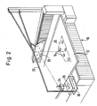
- a CNC router 10 is shown with a machine bed (12), in which a milling unit (14) is provided as a tool, which, numerically controlled by a computer, controls a workpiece (16) profiled in a predetermined manner from a tool Milling drawing not shown plate.
- the workpiece or the plate from which the workpiece is milled out must be held at a distance from the machine table (12) by holding devices during the machining process. According to the exemplary embodiment, this is done by means of vacuum plates (18) which have a vacuum suction cup on both sides and are fixed on the one hand on the machine table (12) and on the other hand on the workpiece (16).
- the vacuum plate (18) should cover the surface of the finished workpiece (16) grasp it at a sufficient distance from the edge profile line to prevent the vacuum plates from being damaged by the milling cutter during the machining process.
- a projection system is provided to facilitate this work of setting up.
- This projection system generates a projection image (20) of the finished workpiece on the work surface of the machine table (12).
- the size of the projection image (20) corresponds to the size of the finished workpiece, i.e. an imaging scale of 1: 1 is preferably chosen. For security reasons, a somewhat reduced image could possibly be generated to ensure a certain edge distance, even if the vacuum plates are guided to the outline.
- the projection device must be designed in such a way that the outline of the workpiece is displayed at the same point at which the milling cutter carries out the machining on the workpiece, i.e. the path traversed by the milling cutter must coincide with the outline of the outline image (20) or have a predetermined edge distance from it.
- the vacuum plates (18) can be placed within the outline of this workpiece with a safe distance from the edge without additional calculations or considerations having to be made.
- the plate-shaped workpiece is then placed on the vacuum plate (18) thus set up. Since the contour lines are also projected onto this plate-like workpiece, it can be placed on the vacuum plates in such a way that as little waste as possible arises.
- the projection system has an overhead projector (24) carried by a gallows (22) or similar device, which projects the template (26) onto the machine table as an outline image (20) via a deflecting mirror (28) attached to the gallows ) maps.
- a gallows (22) or similar device which projects the template (26) onto the machine table as an outline image (20) via a deflecting mirror (28) attached to the gallows ) maps.
- the outer contours are to be machined by the milling cutter, it is sufficient to depict the outline shapes, and the entire outline can be designed as a silhouette.
- work operations for example drilling operations
- these locations can also be marked by the projection device, so that these machining locations can also be taken into account when setting up the vacuum plate.
- the gallows (22) or a similar device can be pivoted and is expediently pivoted out during processing into the position shown in FIG. 1 when the machine is in the working position.
- the template support surface (30) of the projector has two fixed points, not shown in the drawing, which always hit the same place when the boom is swung in. When this correct position is reached, the gallows or the overhead projector are expediently held immovably by a vacuum plate.
- CAD results which are supplied by a computer-controlled plotter and have already been entered as a milling program in the computer, can be displayed as a slide template using the overhead projector (24).
- a flat screen can also be used as a template (26), which immediately shows the outline corresponding to the program.
- Such flat screens that provide a projectable image have been available in liquid crystal construction for some time.
- Such a template (26) designed as a flat screen can also be projected from a projection lamp (32) onto the machine table (12) directly or via a mirror according to FIG. 3.
- the invention has been described above in connection with a milling unit. However, it can also be used to set up workpieces that are subjected to other machining processes.
Landscapes
- Engineering & Computer Science (AREA)
- Mechanical Engineering (AREA)
- Numerical Control (AREA)
- Jigs For Machine Tools (AREA)
Applications Claiming Priority (2)
| Application Number | Priority Date | Filing Date | Title |
|---|---|---|---|
| DE3807199 | 1988-03-04 | ||
| DE19883807199 DE3807199A1 (de) | 1988-03-04 | 1988-03-04 | Verfahren und vorrichtung zum einrichten von werkstuecken |
Publications (2)
| Publication Number | Publication Date |
|---|---|
| EP0331108A2 true EP0331108A2 (fr) | 1989-09-06 |
| EP0331108A3 EP0331108A3 (fr) | 1990-08-16 |
Family
ID=6348916
Family Applications (1)
| Application Number | Title | Priority Date | Filing Date |
|---|---|---|---|
| EP89103499A Withdrawn EP0331108A3 (fr) | 1988-03-04 | 1989-02-28 | Procédé et dispositif pour le positionnement des pièces à usiner |
Country Status (2)
| Country | Link |
|---|---|
| EP (1) | EP0331108A3 (fr) |
| DE (1) | DE3807199A1 (fr) |
Cited By (4)
| Publication number | Priority date | Publication date | Assignee | Title |
|---|---|---|---|---|
| WO2001027702A1 (fr) * | 1999-10-09 | 2001-04-19 | Bae Systems Plc | Systeme de micropositionnement |
| US8978551B2 (en) | 2012-07-25 | 2015-03-17 | Nike, Inc. | Projection assisted printer alignment using remote device |
| US9070055B2 (en) | 2012-07-25 | 2015-06-30 | Nike, Inc. | Graphic alignment for printing to an article using a first display device and a second display device |
| US9254640B2 (en) | 2012-07-25 | 2016-02-09 | Nike, Inc. | Projector assisted alignment and printing |
Families Citing this family (2)
| Publication number | Priority date | Publication date | Assignee | Title |
|---|---|---|---|---|
| DE19510981A1 (de) * | 1995-03-24 | 1996-10-02 | Rainer Knecht | Verfahren und Vorrichtung zum Zuschneiden von Bewehrungen für Betonfertigteile |
| DE102004014054B4 (de) * | 2004-03-23 | 2009-09-03 | Daimler Ag | Verfahren zum Ausrichten eines Werkstücks |
Family Cites Families (4)
| Publication number | Priority date | Publication date | Assignee | Title |
|---|---|---|---|---|
| US2109849A (en) * | 1936-09-22 | 1938-03-01 | Oswego Falls Corp | Apparatus for accurately positioning work relative to a tool |
| US3293439A (en) * | 1963-07-09 | 1966-12-20 | William F Marantette | Two axis photoelectric positioning system including alternate axis activation of photocell |
| JPS61125712A (ja) * | 1984-11-26 | 1986-06-13 | Matsushita Electric Works Ltd | 多層印刷配線板の孔穿設法 |
| DE3517194A1 (de) * | 1985-05-13 | 1986-11-13 | Heinrich Brandt Maschinenbau GmbH, 4920 Lemgo | Verfahren und vorrichtung zum bearbeiten von kanten von plattenfoermigen werkstuecken |
-
1988
- 1988-03-04 DE DE19883807199 patent/DE3807199A1/de active Granted
-
1989
- 1989-02-28 EP EP89103499A patent/EP0331108A3/fr not_active Withdrawn
Cited By (8)
| Publication number | Priority date | Publication date | Assignee | Title |
|---|---|---|---|---|
| WO2001027702A1 (fr) * | 1999-10-09 | 2001-04-19 | Bae Systems Plc | Systeme de micropositionnement |
| US6472676B1 (en) | 1999-10-09 | 2002-10-29 | Bae Systems Plc | Micropositioning system |
| US8978551B2 (en) | 2012-07-25 | 2015-03-17 | Nike, Inc. | Projection assisted printer alignment using remote device |
| US9070055B2 (en) | 2012-07-25 | 2015-06-30 | Nike, Inc. | Graphic alignment for printing to an article using a first display device and a second display device |
| US9248664B2 (en) | 2012-07-25 | 2016-02-02 | Nike, Inc. | Graphic alignment for printing to an article using a first display device and a second display device |
| US9254640B2 (en) | 2012-07-25 | 2016-02-09 | Nike, Inc. | Projector assisted alignment and printing |
| US9427996B2 (en) | 2012-07-25 | 2016-08-30 | Nike, Inc. | Graphic alignment for printing to an article using a first display device and a second display device |
| US9446603B2 (en) | 2012-07-25 | 2016-09-20 | Nike, Inc. | System and method for aligning and printing a graphic on an article |
Also Published As
| Publication number | Publication date |
|---|---|
| DE3807199C2 (fr) | 1991-09-26 |
| DE3807199A1 (de) | 1988-12-01 |
| EP0331108A3 (fr) | 1990-08-16 |
Similar Documents
| Publication | Publication Date | Title |
|---|---|---|
| DE3627110C2 (fr) | ||
| CH622457A5 (fr) | ||
| DE102006013109A1 (de) | Werkzeugmaschine zur Bearbeitung von Platten | |
| DE60004692T2 (de) | Mikropositionierungssystem | |
| WO2020079036A1 (fr) | Procédé d'affichage, assisté par une opération de tri, de représentations de pièces à usiner | |
| DE3320598C2 (de) | Werkzeugmaschine mit einer Vorrichtung zum Entfernen von Bearbeitungsrückständen | |
| EP0331108A2 (fr) | Procédé et dispositif pour le positionnement des pièces à usiner | |
| EP0065247A1 (fr) | Méthode pour fixer et positionner des pièces de précision | |
| DE4013836A1 (de) | Verfahren zum ausschneiden eines zuschnitteils | |
| DE20003048U1 (de) | Verputzvorrichtung, insbesondere Schweißraupenputzmaschine | |
| DE3329266A1 (de) | Von einem industrie-roboter bediente werkzeugmaschine | |
| DE69908257T2 (de) | Schneidetisch zur Behandlung von Glasscheiben | |
| DE602004002682T2 (de) | Tisch zur vorbereitung eines werkstücks vor einer bearbeitung in einer nc-maschine | |
| DE8809008U1 (de) | Vorrichtung zum Einrichten von Werkstücken | |
| DE8907855U1 (de) | Vorrichtung zum Anbringen von Bildelementen auf Tafeln | |
| EP0443398A2 (fr) | Dispositif à ébarber pour châssis de fenêtres ou portes | |
| DE3038887C2 (de) | Verfahren zur Herstellung einer profilierten Kontur an einem Steinblock | |
| DE4117003C2 (de) | Verfahren zur automatischen Bestimmung des Bearbeitungsablaufs einer rechnergesteuerten Werkzeugmaschine | |
| DE2326024C2 (de) | Vorrichtung zum Schneiden von Platten, Folien oder dergleichen | |
| WO2020010373A1 (fr) | Ensemble comprenant un système de traitement cnc et un dispositif d'affichage de réalité augmentée | |
| EP3792713A1 (fr) | Procédé et dispositif de découpe d'éléments de construction | |
| EP3821305B1 (fr) | Ensemble comprenant un système de traitement cnc et un dispositif d'affichage de réalité augmentée | |
| EP0122456A2 (fr) | Procédé et appareil pour la détermination de la section d'image de documents pour la reproduction dans la techique d'impression | |
| DE2655375A1 (de) | Verfahren und vorrichtung zum abschneiden von steinplatten aus einem steinblock | |
| DE20203998U1 (de) | Vorrichtung zum Bearbeiten, Ausschneiden oder Fräsen eines Bauteils aus einem plattenförmigen Werkstück |
Legal Events
| Date | Code | Title | Description |
|---|---|---|---|
| PUAI | Public reference made under article 153(3) epc to a published international application that has entered the european phase |
Free format text: ORIGINAL CODE: 0009012 |
|
| AK | Designated contracting states |
Kind code of ref document: A2 Designated state(s): DE FR GB IT |
|
| PUAL | Search report despatched |
Free format text: ORIGINAL CODE: 0009013 |
|
| AK | Designated contracting states |
Kind code of ref document: A3 Designated state(s): DE FR GB IT |
|
| 17P | Request for examination filed |
Effective date: 19910205 |
|
| STAA | Information on the status of an ep patent application or granted ep patent |
Free format text: STATUS: THE APPLICATION HAS BEEN WITHDRAWN |
|
| 18W | Application withdrawn |
Withdrawal date: 19911217 |