EP0331141A2 - Chaudière - Google Patents
Chaudière Download PDFInfo
- Publication number
- EP0331141A2 EP0331141A2 EP89103568A EP89103568A EP0331141A2 EP 0331141 A2 EP0331141 A2 EP 0331141A2 EP 89103568 A EP89103568 A EP 89103568A EP 89103568 A EP89103568 A EP 89103568A EP 0331141 A2 EP0331141 A2 EP 0331141A2
- Authority
- EP
- European Patent Office
- Prior art keywords
- pipe
- housing
- pipe run
- boiler according
- boiler
- Prior art date
- Legal status (The legal status is an assumption and is not a legal conclusion. Google has not performed a legal analysis and makes no representation as to the accuracy of the status listed.)
- Granted
Links
- 238000007789 sealing Methods 0.000 claims abstract description 21
- 239000007789 gas Substances 0.000 claims abstract description 18
- 229910010293 ceramic material Inorganic materials 0.000 claims abstract description 14
- 238000010438 heat treatment Methods 0.000 claims abstract description 14
- 238000002485 combustion reaction Methods 0.000 claims abstract description 11
- 239000000919 ceramic Substances 0.000 claims description 23
- UGFAIRIUMAVXCW-UHFFFAOYSA-N Carbon monoxide Chemical compound [O+]#[C-] UGFAIRIUMAVXCW-UHFFFAOYSA-N 0.000 claims description 4
- 239000003546 flue gas Substances 0.000 claims description 4
- 238000009434 installation Methods 0.000 claims description 4
- 239000003344 environmental pollutant Substances 0.000 abstract description 6
- 231100000719 pollutant Toxicity 0.000 abstract description 6
- 239000000446 fuel Substances 0.000 abstract description 4
- 230000007797 corrosion Effects 0.000 abstract description 2
- 238000005260 corrosion Methods 0.000 abstract description 2
- 239000003517 fume Substances 0.000 abstract description 2
- 229910000831 Steel Inorganic materials 0.000 description 9
- 239000010959 steel Substances 0.000 description 9
- 238000013461 design Methods 0.000 description 5
- 238000010276 construction Methods 0.000 description 4
- 238000003780 insertion Methods 0.000 description 3
- 230000037431 insertion Effects 0.000 description 3
- 238000011161 development Methods 0.000 description 2
- 230000000694 effects Effects 0.000 description 2
- 230000010354 integration Effects 0.000 description 2
- 239000007788 liquid Substances 0.000 description 2
- 239000000126 substance Substances 0.000 description 2
- 238000012546 transfer Methods 0.000 description 2
- XLYOFNOQVPJJNP-UHFFFAOYSA-N water Substances O XLYOFNOQVPJJNP-UHFFFAOYSA-N 0.000 description 2
- 229910001060 Gray iron Inorganic materials 0.000 description 1
- 239000000853 adhesive Substances 0.000 description 1
- 230000001070 adhesive effect Effects 0.000 description 1
- XAGFODPZIPBFFR-UHFFFAOYSA-N aluminium Chemical compound [Al] XAGFODPZIPBFFR-UHFFFAOYSA-N 0.000 description 1
- 229910052782 aluminium Inorganic materials 0.000 description 1
- 230000003466 anti-cipated effect Effects 0.000 description 1
- 239000011449 brick Substances 0.000 description 1
- 238000004140 cleaning Methods 0.000 description 1
- 238000001125 extrusion Methods 0.000 description 1
- 206010022000 influenza Diseases 0.000 description 1
- 238000004519 manufacturing process Methods 0.000 description 1
- 238000000034 method Methods 0.000 description 1
- 239000011819 refractory material Substances 0.000 description 1
- 229910001220 stainless steel Inorganic materials 0.000 description 1
- 239000010935 stainless steel Substances 0.000 description 1
- 230000007704 transition Effects 0.000 description 1
Images

Classifications
-
- F—MECHANICAL ENGINEERING; LIGHTING; HEATING; WEAPONS; BLASTING
- F28—HEAT EXCHANGE IN GENERAL
- F28F—DETAILS OF HEAT-EXCHANGE AND HEAT-TRANSFER APPARATUS, OF GENERAL APPLICATION
- F28F21/00—Constructions of heat-exchange apparatus characterised by the selection of particular materials
- F28F21/04—Constructions of heat-exchange apparatus characterised by the selection of particular materials of ceramic; of concrete; of natural stone
-
- F—MECHANICAL ENGINEERING; LIGHTING; HEATING; WEAPONS; BLASTING
- F24—HEATING; RANGES; VENTILATING
- F24H—FLUID HEATERS, e.g. WATER OR AIR HEATERS, HAVING HEAT-GENERATING MEANS, e.g. HEAT PUMPS, IN GENERAL
- F24H1/00—Water heaters, e.g. boilers, continuous-flow heaters or water-storage heaters
- F24H1/22—Water heaters other than continuous-flow or water-storage heaters, e.g. water heaters for central heating
- F24H1/24—Water heaters other than continuous-flow or water-storage heaters, e.g. water heaters for central heating with water mantle surrounding the combustion chamber or chambers
- F24H1/26—Water heaters other than continuous-flow or water-storage heaters, e.g. water heaters for central heating with water mantle surrounding the combustion chamber or chambers the water mantle forming an integral body
- F24H1/263—Water heaters other than continuous-flow or water-storage heaters, e.g. water heaters for central heating with water mantle surrounding the combustion chamber or chambers the water mantle forming an integral body with a dry-wall combustion chamber
-
- F—MECHANICAL ENGINEERING; LIGHTING; HEATING; WEAPONS; BLASTING
- F24—HEATING; RANGES; VENTILATING
- F24H—FLUID HEATERS, e.g. WATER OR AIR HEATERS, HAVING HEAT-GENERATING MEANS, e.g. HEAT PUMPS, IN GENERAL
- F24H9/00—Details
- F24H9/14—Arrangements for connecting different sections, e.g. in water heaters
- F24H9/146—Connecting elements of a heat exchanger
Definitions
- the invention relates to a boiler for the combustion of liquid or gaseous fuels according to the preamble of the main claim.
- Such boilers are well known and do not require any special written proof in this respect and in detail. Also known in connection with such boilers are measures and embodiments which are intended to make such boilers condensate-proof, which requirement of such boilers is also more or less well met.
- the relevant measures in this regard range from enamelling the endangered walls via cast inserts to double and multi-layer design of the walls exposed to heating gases.
- the idea of using ceramic material, which has been used since the beginning of furnace and boiler construction, for modern boiler construction is also not new and is being increasingly considered again, especially because corrosion risks are not only caused by the Pollutants present in the fuels and becoming active during combustion, the effects of which could largely be countered satisfactorily with the abovementioned measures, but also because of the pollutants increasingly present in the air.
- the invention is therefore based on the object of improving a boiler of the type mentioned using ceramic material to the effect that it is not only sufficiently resistant to pollutants resulting from the fuels, but also against pollutants from the air, with the proviso that to maintain the proven design and functional principle of boilers of the generic type and to design the ceramic material in such a way that such a boiler can be produced at a reasonable cost.
- the main problem of the liquid and pressure-tight integration of the ceramic body in the water-carrying sheet steel housing is due to its simple geometric shape in the form of a cylinder simply solved that on the one hand provides for polished sealing seat surfaces on the ceramic body or on the other hand arranges the cylindrical ceramic molded body in a continuous sheet steel tube of the water-carrying housing.
- the inner cylinder which is preferably rib-free and forms the combustion chamber wall, is manufactured with undersize so that it can be used in the outer cylinder provided with longitudinal ribs.
- the inner cylinder is then suitably widened by the insertion tolerance measure, so that the inner cylinder comes into contact with the free ends of the longitudinal ribs of the other cylinder.
- the two ceramic cylinders are advantageously of the same length, the necessary heating gas overflow opening for the transfer of the heating gases into the heating gas trains being formed from a plurality of slots in the inner tube train and each slot leading to at least one of the individual trains delimited by the longitudinal ribs.
- the edges are advantageously formed by through openings in the front and rear walls of the water-carrying housing in the form of at least one ring groove and this is either formed from the opening edge areas of the walls or molded onto them as an additional part, which is closer is explained.
- the ceramic tube can be slightly tapered at its insertion end be so that it can better pass through the sealing rings, which automatically get an interference fit between the ring groove and the ceramic body after passage of the conical area.
- the additional part forming the annular groove is designed as a conical ring collar which can be fastened to the front and rear walls of the housing and encloses a wedge-shaped gusset space with the front and rear walls.
- the seal and the ring collar are to be dimensioned or designed so that there is a press fit for the seal when the ring collar is attached to the front and rear walls. Since in this embodiment the ceramic tube can first be inserted into the water-bearing housing without seals, an advantageous embodiment with regard to the outer tube is to provide the ground sealing seat surfaces with at least one surface-enlarging profile, into which the sealing ring is then pressed after the ring collar has been tightened.
- the two ceramic tubes are arranged in a sealing tube made of sheet steel and welded to the water-carrying housing.
- a sealing tube made of sheet steel and welded to the water-carrying housing.
- the boiler according to the invention is preferably designed such that the closure carrying the burner and the flue gas collection chamber are arranged on the front and rear walls of the housing without contact with the two ceramic tubes. This is also provided because it would be absolutely problematic to attach these burner and fume cupboard tube closures to the ceramic bodies themselves.
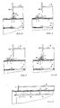
- the boiler consists in a known manner of a water-carrying housing 16, which is penetrated by a pipe 1 enclosing the combustion chamber 8 and the heating gas-carrying rooms divided into individual sections, which is closed at one end with a closure 23 carrying the burner 25 and at the other End in an exhaust gas collection chamber 24 with exhaust gas connection 24 'opens.
- the pipe run 1 is formed from liquid-tight ceramic material, which is ground in the area of the passage openings 2 of the front and rear walls 3, 4 of the housing to form sealing seat surfaces 5.
- At least one sealing ring 7 is placed between the opening edges 6 (see in particular FIGS. 3 - 6) of the front and rear walls 3, 4 of the housing and the ground sealing seat surfaces of the outer tubing 1.
- a second, smaller diameter, surrounding the combustion chamber 8 is seated in the tube pull 1 and provided on the extractor side with an inserted bottom 9, pipe tube 10, which is also made of ceramic material.
- the bottom 9 can also consist of ceramic material or of another suitable, refractory material.
- longitudinal ribs 12 are provided in the annular cylindrical space 11 between the two pipe runs 1 and 10 as parts of the outer pipe run 1, which, as can be seen in FIG. 2, rest with their free ends 13 on the wall of the inner pipe run 10.
- the two pipe runs are advantageously of the same length, as a result of which the two pipe runs can be mutually supported over their entire length.
- the heating gas overflow opening 14 is formed from a plurality of slots 14 'on the inner tube train 10, each slot 14' to at least one of the the longitudinal ribs 12 limited individual trains 15 (Fig. 2) leads. Possibly. a slot can be made so wide that a slot detects several individual trains 15 lying next to one another.
- FIGS. 3 to 6 With regard to the attachment of seals in the form of sealing rings 7, reference is made to FIGS. 3 to 6. As can be seen from these representations, the edges 6 of the through openings 2 of the front and rear walls 3 and 4 of the housing 16 are designed in the form of at least one annular groove 17 (FIGS. 3, 4), these opening regions of the walls 3, 4 molded (Fig. 4, 5) or as an additional part 18 (Fig. 3) is molded onto this. With regard to the requirements to be observed, reference is made to the above explanations in this regard.
- the ground you tion seat surface 5 is provided with a plurality of surface-enlarging profiles 20, into which the corresponding cross-section-sized sealing ring 19 when tightening the ring collar 18 ', as shown, presses.
- the embodiment according to FIG. 7 differs from the previously described embodiment only in that this boiler design advantageously does without special seals, as described above.
- the pipe run 1 is in contact with the pipe run 21 or between the pipe run 1 and the pipe run 21 an elastic, heat-conducting mass layer 22 is arranged.
- both constructions have in common that the outer ceramic tube 1 sits, so to speak, "floating" in the water-carrying housing 16.
- water-carrying housing 16 does not necessarily have to consist of sheet steel, but can also be formed, for example, from gray cast iron, aluminum, stainless steel or even from ceramic. Even if the housing 16 is made of ceramic, the "floating" integration of the two pipe runs 1 and 10 is essential since the housing 16, because it is cooled, is subjected to different thermal loads than the two pipe runs 1 and 10.
Landscapes
- Engineering & Computer Science (AREA)
- General Engineering & Computer Science (AREA)
- Thermal Sciences (AREA)
- Mechanical Engineering (AREA)
- Physics & Mathematics (AREA)
- Chemical & Material Sciences (AREA)
- Combustion & Propulsion (AREA)
- Ceramic Engineering (AREA)
- Steam Or Hot-Water Central Heating Systems (AREA)
- Air Supply (AREA)
- Combustion Of Fluid Fuel (AREA)
- Fire-Extinguishing Compositions (AREA)
- Instantaneous Water Boilers, Portable Hot-Water Supply Apparatuses, And Control Of Portable Hot-Water Supply Apparatuses (AREA)
Priority Applications (1)
| Application Number | Priority Date | Filing Date | Title |
|---|---|---|---|
| AT89103568T ATE77470T1 (de) | 1988-03-03 | 1989-03-01 | Heizkessel. |
Applications Claiming Priority (2)
| Application Number | Priority Date | Filing Date | Title |
|---|---|---|---|
| DE3806804A DE3806804A1 (de) | 1988-03-03 | 1988-03-03 | Heizungskessel |
| DE3806804 | 1988-03-03 |
Publications (3)
| Publication Number | Publication Date |
|---|---|
| EP0331141A2 true EP0331141A2 (fr) | 1989-09-06 |
| EP0331141A3 EP0331141A3 (en) | 1990-04-18 |
| EP0331141B1 EP0331141B1 (fr) | 1992-06-17 |
Family
ID=6348660
Family Applications (1)
| Application Number | Title | Priority Date | Filing Date |
|---|---|---|---|
| EP89103568A Expired - Lifetime EP0331141B1 (fr) | 1988-03-03 | 1989-03-01 | Chaudière |
Country Status (3)
| Country | Link |
|---|---|
| EP (1) | EP0331141B1 (fr) |
| AT (1) | ATE77470T1 (fr) |
| DE (2) | DE3806804A1 (fr) |
Family Cites Families (9)
| Publication number | Priority date | Publication date | Assignee | Title |
|---|---|---|---|---|
| DE2645717C3 (de) * | 1976-10-09 | 1979-10-25 | Hans 3559 Battenberg Viessmann | Heizkessel für flüssige oder gasförmige Brennstoffe |
| DE2906362C2 (de) * | 1979-02-19 | 1981-02-05 | Hans 3559 Battenberg Viessmann | Heizungskessel für flüssige oder gasförmige Brennstoffe |
| DE3014245C2 (de) * | 1980-04-14 | 1984-06-28 | Kernforschungsanlage Jülich GmbH, 5170 Jülich | Verbrennungs- und Heizeinrichtung mit einem keramischen Brennerkopf |
| DE3025651C2 (de) * | 1980-07-07 | 1983-02-17 | Hans 3559 Battenberg Vießmann | Heizungskessel |
| DE3331340A1 (de) * | 1983-08-31 | 1985-04-11 | Buderus Ag, 6330 Wetzlar | Zentralheizungskessel |
| DE3413968A1 (de) * | 1984-03-31 | 1985-10-10 | Didier-Werke Ag, 6200 Wiesbaden | Vorrichtung zur verbrennungsunterstuetzung fuer einen oel- oder gasbrenner |
| US4538551A (en) * | 1984-06-20 | 1985-09-03 | Vapor Corporation | Refractory choke for a high intensity combustor |
| DE3425259C2 (de) * | 1984-07-10 | 1986-10-23 | Wolfgang 5063 Overath Schmitter | Wärmeerzeuger |
| DE3535341A1 (de) * | 1985-10-03 | 1987-04-09 | Viessmann Hans | Heizkessel fuer fluessige oder gasfoermige brennstoffe |
-
1988
- 1988-03-03 DE DE3806804A patent/DE3806804A1/de not_active Withdrawn
-
1989
- 1989-03-01 AT AT89103568T patent/ATE77470T1/de not_active IP Right Cessation
- 1989-03-01 DE DE8989103568T patent/DE58901651D1/de not_active Expired - Lifetime
- 1989-03-01 EP EP89103568A patent/EP0331141B1/fr not_active Expired - Lifetime
Also Published As
| Publication number | Publication date |
|---|---|
| DE58901651D1 (de) | 1992-07-23 |
| EP0331141A3 (en) | 1990-04-18 |
| EP0331141B1 (fr) | 1992-06-17 |
| DE3806804A1 (de) | 1989-09-14 |
| ATE77470T1 (de) | 1992-07-15 |
Similar Documents
| Publication | Publication Date | Title |
|---|---|---|
| DE2323986A1 (de) | Flammenrohrkessel fuer gasfoermige und fluessige brennstoffe | |
| DE2629962C2 (de) | Vorrichtung zur Schalldämpfung eines Strahlheizrohres für einen Industrieofen | |
| DE3601000A1 (de) | Wasserheizkessel | |
| EP0331141B1 (fr) | Chaudière | |
| DE2814155A1 (de) | Waermetauscher fuer verbrennungsanlagen | |
| EP0387584B1 (fr) | Tuyau de tirage pour gaz de chauffage | |
| EP0209703B1 (fr) | Cartouche incandescente pour fours, en particulier pour chaudières ainsi que four avec une telle cartouche | |
| AT395209B (de) | Heizeinrichtung | |
| CH635189A5 (en) | Heating boiler for burning liquid or gaseous fuels | |
| DE3502661C2 (fr) | ||
| AT406302B (de) | Wasserheizer | |
| DE2856338B2 (de) | Heizungskessel für flüssige oder gasförmige Brennstoffe | |
| DE2025472C3 (de) | Heizungskessel | |
| DE951999C (de) | Rauchrohrwaermeaustauscher fuer Auspuffgase | |
| EP0430061B1 (fr) | Chaudière de chauffage | |
| LU85997A1 (de) | Heizungskessel fuer fluessige oder gasfoermige brennstoffe | |
| DE3045387C2 (de) | Rauchgaswärmetauscher | |
| DE7305328U (de) | Mehrzugkessel | |
| DE29718443U1 (de) | Rauchgasabzug, insbesondere für Heizkessel | |
| DE8327692U1 (de) | Heizgaszugrohr | |
| DE2361834A1 (de) | Waermeerzeugungsanlage und schachtbauteil sowie schacht hierfuer | |
| DE8631630U1 (de) | Einschiebbare Brennkammer für Heizkessel mit Gebläsebrenner | |
| CH685260A5 (de) | Heizkessel für flüssige oder gasförmige Brennstoffe. | |
| DE8517158U1 (de) | Glüheinsatz für Öfen, insbesondere Heizungskessel | |
| DE3310098A1 (de) | Heizungskessel |
Legal Events
| Date | Code | Title | Description |
|---|---|---|---|
| PUAI | Public reference made under article 153(3) epc to a published international application that has entered the european phase |
Free format text: ORIGINAL CODE: 0009012 |
|
| AK | Designated contracting states |
Kind code of ref document: A2 Designated state(s): AT BE CH DE FR GB IT LI NL |
|
| PUAL | Search report despatched |
Free format text: ORIGINAL CODE: 0009013 |
|
| AK | Designated contracting states |
Kind code of ref document: A3 Designated state(s): AT BE CH DE FR GB IT LI NL |
|
| 17P | Request for examination filed |
Effective date: 19900411 |
|
| 17Q | First examination report despatched |
Effective date: 19910115 |
|
| GRAA | (expected) grant |
Free format text: ORIGINAL CODE: 0009210 |
|
| AK | Designated contracting states |
Kind code of ref document: B1 Designated state(s): AT BE CH DE FR GB IT LI NL |
|
| REF | Corresponds to: |
Ref document number: 77470 Country of ref document: AT Date of ref document: 19920715 Kind code of ref document: T |
|
| ET | Fr: translation filed | ||
| REF | Corresponds to: |
Ref document number: 58901651 Country of ref document: DE Date of ref document: 19920723 |
|
| ITF | It: translation for a ep patent filed | ||
| GBT | Gb: translation of ep patent filed (gb section 77(6)(a)/1977) | ||
| PLBE | No opposition filed within time limit |
Free format text: ORIGINAL CODE: 0009261 |
|
| STAA | Information on the status of an ep patent application or granted ep patent |
Free format text: STATUS: NO OPPOSITION FILED WITHIN TIME LIMIT |
|
| 26N | No opposition filed | ||
| PGFP | Annual fee paid to national office [announced via postgrant information from national office to epo] |
Ref country code: GB Payment date: 19990225 Year of fee payment: 11 |
|
| PGFP | Annual fee paid to national office [announced via postgrant information from national office to epo] |
Ref country code: BE Payment date: 19990303 Year of fee payment: 11 |
|
| PGFP | Annual fee paid to national office [announced via postgrant information from national office to epo] |
Ref country code: CH Payment date: 19990326 Year of fee payment: 11 |
|
| PGFP | Annual fee paid to national office [announced via postgrant information from national office to epo] |
Ref country code: NL Payment date: 19990331 Year of fee payment: 11 Ref country code: FR Payment date: 19990331 Year of fee payment: 11 Ref country code: DE Payment date: 19990331 Year of fee payment: 11 Ref country code: AT Payment date: 19990331 Year of fee payment: 11 |
|
| PG25 | Lapsed in a contracting state [announced via postgrant information from national office to epo] |
Ref country code: GB Free format text: LAPSE BECAUSE OF NON-PAYMENT OF DUE FEES Effective date: 20000301 Ref country code: AT Free format text: LAPSE BECAUSE OF NON-PAYMENT OF DUE FEES Effective date: 20000301 |
|
| PG25 | Lapsed in a contracting state [announced via postgrant information from national office to epo] |
Ref country code: LI Free format text: LAPSE BECAUSE OF NON-PAYMENT OF DUE FEES Effective date: 20000331 Ref country code: CH Free format text: LAPSE BECAUSE OF NON-PAYMENT OF DUE FEES Effective date: 20000331 Ref country code: BE Free format text: LAPSE BECAUSE OF NON-PAYMENT OF DUE FEES Effective date: 20000331 |
|
| BERE | Be: lapsed |
Owner name: VIESSMANN HANS Effective date: 20000331 |
|
| PG25 | Lapsed in a contracting state [announced via postgrant information from national office to epo] |
Ref country code: NL Free format text: LAPSE BECAUSE OF NON-PAYMENT OF DUE FEES Effective date: 20001001 |
|
| GBPC | Gb: european patent ceased through non-payment of renewal fee |
Effective date: 20000301 |
|
| REG | Reference to a national code |
Ref country code: CH Ref legal event code: PL |
|
| PG25 | Lapsed in a contracting state [announced via postgrant information from national office to epo] |
Ref country code: FR Free format text: LAPSE BECAUSE OF NON-PAYMENT OF DUE FEES Effective date: 20001130 |
|
| NLV4 | Nl: lapsed or anulled due to non-payment of the annual fee |
Effective date: 20001001 |
|
| REG | Reference to a national code |
Ref country code: FR Ref legal event code: ST |
|
| PG25 | Lapsed in a contracting state [announced via postgrant information from national office to epo] |
Ref country code: DE Free format text: LAPSE BECAUSE OF NON-PAYMENT OF DUE FEES Effective date: 20010103 |
|
| PG25 | Lapsed in a contracting state [announced via postgrant information from national office to epo] |
Ref country code: IT Free format text: LAPSE BECAUSE OF NON-PAYMENT OF DUE FEES;WARNING: LAPSES OF ITALIAN PATENTS WITH EFFECTIVE DATE BEFORE 2007 MAY HAVE OCCURRED AT ANY TIME BEFORE 2007. THE CORRECT EFFECTIVE DATE MAY BE DIFFERENT FROM THE ONE RECORDED. Effective date: 20050301 |