EP0331295B1 - Assemblage de pipelines pour séparer au moins un courant diphasique - Google Patents
Assemblage de pipelines pour séparer au moins un courant diphasique Download PDFInfo
- Publication number
- EP0331295B1 EP0331295B1 EP89301091A EP89301091A EP0331295B1 EP 0331295 B1 EP0331295 B1 EP 0331295B1 EP 89301091 A EP89301091 A EP 89301091A EP 89301091 A EP89301091 A EP 89301091A EP 0331295 B1 EP0331295 B1 EP 0331295B1
- Authority
- EP
- European Patent Office
- Prior art keywords
- pipeline
- riser
- gas
- junction
- main
- Prior art date
- Legal status (The legal status is an assumption and is not a legal conclusion. Google has not performed a legal analysis and makes no representation as to the accuracy of the status listed.)
- Expired
Links
Images

Classifications
-
- F—MECHANICAL ENGINEERING; LIGHTING; HEATING; WEAPONS; BLASTING
- F17—STORING OR DISTRIBUTING GASES OR LIQUIDS
- F17D—PIPE-LINE SYSTEMS; PIPE-LINES
- F17D1/00—Pipe-line systems
- F17D1/005—Pipe-line systems for a two-phase gas-liquid flow
-
- E—FIXED CONSTRUCTIONS
- E21—EARTH OR ROCK DRILLING; MINING
- E21B—EARTH OR ROCK DRILLING; OBTAINING OIL, GAS, WATER, SOLUBLE OR MELTABLE MATERIALS OR A SLURRY OF MINERALS FROM WELLS
- E21B43/00—Methods or apparatus for obtaining oil, gas, water, soluble or meltable materials or a slurry of minerals from wells
- E21B43/34—Arrangements for separating materials produced by the well
- E21B43/36—Underwater separating arrangements
-
- E—FIXED CONSTRUCTIONS
- E21—EARTH OR ROCK DRILLING; MINING
- E21B—EARTH OR ROCK DRILLING; OBTAINING OIL, GAS, WATER, SOLUBLE OR MELTABLE MATERIALS OR A SLURRY OF MINERALS FROM WELLS
- E21B2200/00—Special features related to earth drilling for obtaining oil, gas or water
- E21B2200/09—Detecting, eliminating, preventing liquid slugs in production pipes
Definitions
- the present invention relates to a system for the separation underwater of the phases of a two-phase fluid flow into respective risers, e.g. as with an offshore platform, where oil and gas are transported by a pipeline along the seabed and by risers to the platform.
- a two-phase flow in a horizontal pipeline system gives various flow patterns depending on the pipe diameter, geometry temperature and type of oil. Generally said, the flow pattern can be divided into the following categories: stratified, bubble, slug and annular flow.
- a two-phase flow in a vertical pipe can also be divided into various flow patterns.
- the slug flow will give the greatest problems as mentioned above.
- the extreme slugging depends on the geometry and occurs only in the riser when the oil and gas velocity is so low that the horizontal flow is stratified.
- Normal slugging is hydrodynamic and can be formed both in the horizontal and the vertical pipe section.
- a separator for separation of the liquid- and gaseous phase has previously been developed.
- the gas and oil are separated by feeding the flow from one common pipe into two or more parallel pipes.
- Such separators require large space and are expensive to build.
- a common feature of the aforementioned three types of slug catchers is that all three make use of some type of phase separator on the platform. Since the total capacity of the slug catchers has to be-.larger than the largest expected slugs it will occupy expensive and limited space on the platform.
- a system for underwater phase separation of a fluid flow having at least two phases, such as oil and gas, from a seabed oil well including an underwater pipeline, a main riser connected to the pipeline and a secondary riser provided with flow restriction means and connected to the pipeline via a T-junction located upstream of the main riser is characterised in that the main riser is connected to a storage tank, the secondary riser is for gas transport and is connected to a gas scrubber, the flow restriction means is a controlled regulating valve, and in that there is a control means in the pipeline between the risers and responsive to the position of the liquid/gas interface along the pipeline so as to control the setting of the regulating valve to maintain the position of the said interface constant.
- This allows for a total separation of the phases of a two-phase flow on the seabed and outside the platform, e.g. in a pipe system connecting the oil/gas pipeline on the seabed with the processing plant onshore.
- the system is especially designed to deal with extreme slugs which occur normally at low liquid and gas velocity, i.e. at startup and shut-down of the production.
- the main advantage of the system, which is designed to be located on the seabed, is that it has no moving parts, is simple and easy to manufacture, and is reliable and simple to maintain.
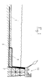
- Figure 1 illustrates an offshore platform 10 for transportation and processing of oil and gas from a remote subsea installation or well via riser 2 to the processing plant on the platform 10.
- the pipeline 1 is connected to a separate secondary riser 3 via T-junction 5 located at a distance X from the riser 2.
- the secondary riser is connected to a gas scrubber 6 located on the platform.
- a storage tank 4 is provided with a drainpipe 12 for the oil and one discharge pipe 13 for any gas that has evaporated from or was mixed with the oil.
- a detection means 8 is provided to determine the location along the pipe 1 of any oil/gas interface. As shown, this detector comprises five capacitive detectors K1-K5 arranged in the pipeline section between the T-junction 5 and the riser 2. The capacitive detectors K1-K5 detect the presence of an oil/gas interface in the pipeline. The capacitive detectors are connected to a level indicator and give electrical signals to a control unit (not shown) which controls a regulating valve 7 located on the secondary riser 3.
- the oil and gas transported in the main pipeline 1 are separated at the T-junction 5, where the gas components of the two-phase flow pass into the secondary riser 3 and the oil components pass into the pipeline 1 downstream of the T-junction and into the riser 2.
- the pipeline 1 between the T-junction and the riser 2 should be slightly sloped so that a liquid seal is formed in the riser.
- the regulating valve 7, by venting the gas, regulates the pressure in the pipeline 1 and in the riser 2. The regulation is done according to the signals from the capacitive detectors K1-K5 in the pipeline.
- the regulating valve 7 will open at increasing gas pressure in the secondary riser when the liquid/gas interface reaches the detector K1.
- the riser 2 will therefore contain fluid which is 100% oil and the oil/gas interface at all times will be located between the T-junction and the riser 2.
- the accuracy of the oil/gas interface detection is of course dependent on the number of detectors situated in the pipeline and the distance between them.
- the detection means may comprise more or less than five capacitive detectors or equivalent detectors of another type capable of detecting the presence of the liquid/gas interface.
- Such detectors might comprise pressure sensors located in the scrubber, the storing tank and the pipeline. By means of the difference and the variation of pressure the position of the liquid/gas interface in the pipeline can be determined.
- the pipes may have different diameters and lengths. To determine the optimum length of the pipes it is important to make sure that the system can deal with the peak values of slugs. Tests have shown that a distance X between the T-junction 5 and the riser 2 should be at least two times the height of the riser.
- the pipes can be of different diameters, it is regarded as being an advantage to be able to clean the inside of the pipes by using a "pig".
- the pipeline 1 and the risers 2, 3 should therefore have the same diameter and be as free as possible of obstacles such as valves, bends, etc.
- the angle of inclination of the pipeline between the tee section and the riser is also important. Tests have indicated that it should be approximately 2° to the horizontal. To achieve the best separation of the two-phase flow the angle between the upright of the T-junction 5 and the main pipeline 1 may be an angle other than 90°, as illustrated in the drawings.
Landscapes
- Engineering & Computer Science (AREA)
- Life Sciences & Earth Sciences (AREA)
- Mining & Mineral Resources (AREA)
- Geology (AREA)
- Fluid Mechanics (AREA)
- Environmental & Geological Engineering (AREA)
- Physics & Mathematics (AREA)
- General Life Sciences & Earth Sciences (AREA)
- Geochemistry & Mineralogy (AREA)
- General Engineering & Computer Science (AREA)
- Mechanical Engineering (AREA)
- Pipeline Systems (AREA)
- Earth Drilling (AREA)
- Paper (AREA)
- Maintenance And Management Of Digital Transmission (AREA)
Claims (7)
- Système de séparation sous-marine de phases d'un débit de fluide comportant un minimum de deux phases, telles que l'huile et le gaz, à partir d'un puits de pétrole au fond de la mer, le système comportant un oléo-gazoduc sous-marin, un montant principal raccordé à l'oléo-gazoduc sous-marin et un montant secondaire comportant des moyens d'étranglement du débit et raccordé à l'oléo-gazoduc, caractérisé en ce que, le montant principal (2) est raccordé à un réservoir (4), le montant secondaire (3) prévu pour transporter le gaz est raccordé à un épurateur de gaz (6), les moyens d'étranglement (7) consistent d'un robinet régulateur, et en ce que des moyens de commande (8) sont prévus dans l'oléo-gazoduc entre les montants et répondent à la position de l'interface liquide/gaz le long de l'oléo-gazoduc de manière à ajuster le réglage du robinet régulateur (7) de manière à maintenir constante la position de la dite interface.
- Système selon la revendication 1 dont les moyens régulateurs comportent des moyens capteurs K¹ à K⁵ situés au minimum le long de l'oléo-gazoduc entre le montant principal (2) et le raccord en Té (5) raccordant le montant secondaire (3) à l'oléo-gazoduc.
- Système selon la revendication 2 dont les moyens capteurs comportent une série de capteurs capacitifs K¹-K⁵ situés dans l'oléo-gazoduc, chacun répondant à la proximité de l'interface du gaz/liquide.
- Système selon la revendication 2 dont les moyens capteurs comportent des capteurs de pression, ces derniers étant également agencés dans l'épurateur de gaz (6) et le réservoir (4), tous deux étant situés dans le matériel de séparation.
- Système selon l'une des revendications précédentes selon lesquelles la distance entre le raccord en Té (5) reliant le montant secondaire (3) à l'oléo-gazoduc (1) et au montant principal (2) mesure au minimum deux fois la hauteur du montant principal.
- Système selon l'une des revendications précédentes dont le tronçon d'oléo-gazoduc situé entre les deux montants est incliné pour s'éloigner du raccord en Té.
- Système selon la revendication 6 dont l'angle d'inclinaison est de 2°.
Applications Claiming Priority (2)
| Application Number | Priority Date | Filing Date | Title |
|---|---|---|---|
| NO880465A NO163424C (no) | 1988-02-03 | 1988-02-03 | Integrert system for omforming av stroemningsmoenster. |
| NO880465 | 1988-02-03 |
Publications (2)
| Publication Number | Publication Date |
|---|---|
| EP0331295A1 EP0331295A1 (fr) | 1989-09-06 |
| EP0331295B1 true EP0331295B1 (fr) | 1992-12-09 |
Family
ID=19890632
Family Applications (1)
| Application Number | Title | Priority Date | Filing Date |
|---|---|---|---|
| EP89301091A Expired EP0331295B1 (fr) | 1988-02-03 | 1989-02-03 | Assemblage de pipelines pour séparer au moins un courant diphasique |
Country Status (5)
| Country | Link |
|---|---|
| EP (1) | EP0331295B1 (fr) |
| BR (1) | BR8900411A (fr) |
| DE (1) | DE68903771T2 (fr) |
| ES (1) | ES2036339T3 (fr) |
| NO (1) | NO163424C (fr) |
Families Citing this family (12)
| Publication number | Priority date | Publication date | Assignee | Title |
|---|---|---|---|---|
| GB8917026D0 (en) * | 1989-07-25 | 1989-09-13 | Shell Int Research | Method and apparatus for preventing slug growth in a pipeline |
| BR9303910A (pt) * | 1993-09-27 | 1995-05-30 | Petroleo Brasileiro Sa | Método para eliminação de intermitência severa em linhas submarinas de fluxo multifásico |
| BR9602747A (pt) * | 1996-06-12 | 1998-09-08 | Petroleo Brasileiro Sa | Método e aparelhagem para produç o submarina de petróleo através da injeç o intermitente de gás |
| EP1409834A2 (fr) | 2000-01-17 | 2004-04-21 | Lattice Intellectual Property Limited | Prevention de la formation de bouchons |
| GB0000945D0 (en) * | 2000-01-17 | 2000-03-08 | Bg Intellectual Pty Ltd | Control of slugging in a riser |
| NO320414B1 (no) * | 2002-02-04 | 2005-12-05 | Statoil Asa | Undervanns flerfaserorledning |
| NO316840B1 (no) * | 2002-08-16 | 2004-05-24 | Norsk Hydro As | Rorseparator for separasjon av fluid, spesielt olje, gass og vann |
| FR2875260B1 (fr) * | 2004-09-13 | 2006-10-27 | Inst Francais Du Petrole | Systeme pour neutraliser la formation de bouchon de liquide dans une colonne montante |
| DE602006016475D1 (de) * | 2005-11-28 | 2010-10-07 | Shell Int Research | Verfahren zum empfang von fluid aus einem erdgasrohr |
| US8726982B2 (en) | 2008-04-28 | 2014-05-20 | Shell Oil Company | Method of producing gaseous and liquid components from one or more multi-phase streams and apparatus therefor |
| AU2009242194B2 (en) * | 2008-04-28 | 2012-02-09 | Shell Internationale Research Maatschappij B.V. | Method of bypassing a pipeline in a multiple pipeline system |
| IT1396435B1 (it) | 2009-11-16 | 2012-11-23 | Eni Spa | Procedimento di separazione di una corrente multifise che scorre lungo una condotta mediante giunto a t. |
Family Cites Families (3)
| Publication number | Priority date | Publication date | Assignee | Title |
|---|---|---|---|---|
| US4160652A (en) * | 1977-08-26 | 1979-07-10 | Texas Eastern Engineering, Ltd. | Method and apparatus for handling the fluids in a two-phase flow pipeline system |
| NO157467C (no) * | 1985-09-18 | 1988-03-23 | Sintef | Anordning for oppsamling av vaeskeplugger i en gassfoerende roerledning. |
| US4708793A (en) * | 1986-06-13 | 1987-11-24 | Atlantic Richfield Company | System for separating gas-liquid flowstreams |
-
1988
- 1988-02-03 NO NO880465A patent/NO163424C/no unknown
-
1989
- 1989-01-31 BR BR898900411A patent/BR8900411A/pt not_active IP Right Cessation
- 1989-02-03 EP EP89301091A patent/EP0331295B1/fr not_active Expired
- 1989-02-03 DE DE8989301091T patent/DE68903771T2/de not_active Expired - Fee Related
- 1989-02-03 ES ES198989301091T patent/ES2036339T3/es not_active Expired - Lifetime
Also Published As
| Publication number | Publication date |
|---|---|
| BR8900411A (pt) | 1989-09-26 |
| EP0331295A1 (fr) | 1989-09-06 |
| NO880465L (no) | 1989-08-04 |
| NO880465D0 (no) | 1988-02-03 |
| ES2036339T3 (es) | 1993-05-16 |
| DE68903771D1 (de) | 1993-01-21 |
| DE68903771T2 (de) | 1993-05-13 |
| NO163424B (no) | 1990-02-12 |
| NO163424C (no) | 1991-11-28 |
Similar Documents
| Publication | Publication Date | Title |
|---|---|---|
| EP0331295B1 (fr) | Assemblage de pipelines pour séparer au moins un courant diphasique | |
| US10434441B2 (en) | Apparatus and method for gas-liquid separation | |
| US6651745B1 (en) | Subsea riser separator system | |
| US8002121B2 (en) | In-line flow separation of fluids in a pipe separator | |
| CN101084363B (zh) | 用于控制多相流体的流动的方法、系统以及控制器 | |
| US12286876B2 (en) | Drain apparatus for a subsea pipeline | |
| AU2002236364A1 (en) | An apparatus for separation of a liquid from a multiphase fluid flow | |
| US5507955A (en) | Method of operating hydrocyclone systems by adding water to maintain flow rates | |
| US4519815A (en) | Slug-catching method and apparatus | |
| EP0767699B1 (fr) | Suppression d'un ecoulement a bouchons dans un flux de fluide polyphasique | |
| EP0410522A2 (fr) | Méthode et dispositif pour prévenir la croissance des dépôts dans une tuyauterie | |
| EP0238535B1 (fr) | Collecteur de bouchon pouvant etre nettoye | |
| US5294214A (en) | Gas eliminator for offshore oil transfer pipelines | |
| US4613349A (en) | Fluid separator and flow stabilization structure | |
| US4553989A (en) | Safety system for removing any risk of carrying liquids to the nose of the flare or to the vent-hole during burning or dispersion of the gases associated with production |
Legal Events
| Date | Code | Title | Description |
|---|---|---|---|
| PUAI | Public reference made under article 153(3) epc to a published international application that has entered the european phase |
Free format text: ORIGINAL CODE: 0009012 |
|
| AK | Designated contracting states |
Kind code of ref document: A1 Designated state(s): DE ES FR GB IT NL |
|
| RTI1 | Title (correction) | ||
| 17P | Request for examination filed |
Effective date: 19900115 |
|
| 17Q | First examination report despatched |
Effective date: 19910506 |
|
| GRAA | (expected) grant |
Free format text: ORIGINAL CODE: 0009210 |
|
| AK | Designated contracting states |
Kind code of ref document: B1 Designated state(s): DE ES FR GB IT NL |
|
| REF | Corresponds to: |
Ref document number: 68903771 Country of ref document: DE Date of ref document: 19930121 |
|
| ET | Fr: translation filed | ||
| ITF | It: translation for a ep patent filed | ||
| REG | Reference to a national code |
Ref country code: ES Ref legal event code: FG2A Ref document number: 2036339 Country of ref document: ES Kind code of ref document: T3 |
|
| PLBE | No opposition filed within time limit |
Free format text: ORIGINAL CODE: 0009261 |
|
| STAA | Information on the status of an ep patent application or granted ep patent |
Free format text: STATUS: NO OPPOSITION FILED WITHIN TIME LIMIT |
|
| 26N | No opposition filed | ||
| PGFP | Annual fee paid to national office [announced via postgrant information from national office to epo] |
Ref country code: ES Payment date: 19940125 Year of fee payment: 6 |
|
| PGFP | Annual fee paid to national office [announced via postgrant information from national office to epo] |
Ref country code: GB Payment date: 19940126 Year of fee payment: 6 |
|
| PGFP | Annual fee paid to national office [announced via postgrant information from national office to epo] |
Ref country code: FR Payment date: 19940127 Year of fee payment: 6 |
|
| PGFP | Annual fee paid to national office [announced via postgrant information from national office to epo] |
Ref country code: DE Payment date: 19940222 Year of fee payment: 6 |
|
| PGFP | Annual fee paid to national office [announced via postgrant information from national office to epo] |
Ref country code: NL Payment date: 19940228 Year of fee payment: 6 |
|
| PG25 | Lapsed in a contracting state [announced via postgrant information from national office to epo] |
Ref country code: GB Effective date: 19950203 |
|
| PG25 | Lapsed in a contracting state [announced via postgrant information from national office to epo] |
Ref country code: ES Free format text: LAPSE BECAUSE OF NON-PAYMENT OF DUE FEES Effective date: 19950204 |
|
| PG25 | Lapsed in a contracting state [announced via postgrant information from national office to epo] |
Ref country code: NL Effective date: 19950901 |
|
| GBPC | Gb: european patent ceased through non-payment of renewal fee |
Effective date: 19950203 |
|
| PG25 | Lapsed in a contracting state [announced via postgrant information from national office to epo] |
Ref country code: FR Effective date: 19951031 |
|
| NLV4 | Nl: lapsed or anulled due to non-payment of the annual fee |
Effective date: 19950901 |
|
| PG25 | Lapsed in a contracting state [announced via postgrant information from national office to epo] |
Ref country code: DE Effective date: 19951101 |
|
| REG | Reference to a national code |
Ref country code: FR Ref legal event code: ST |
|
| REG | Reference to a national code |
Ref country code: ES Ref legal event code: FD2A Effective date: 19990301 |
|
| PG25 | Lapsed in a contracting state [announced via postgrant information from national office to epo] |
Ref country code: IT Free format text: LAPSE BECAUSE OF NON-PAYMENT OF DUE FEES;WARNING: LAPSES OF ITALIAN PATENTS WITH EFFECTIVE DATE BEFORE 2007 MAY HAVE OCCURRED AT ANY TIME BEFORE 2007. THE CORRECT EFFECTIVE DATE MAY BE DIFFERENT FROM THE ONE RECORDED. Effective date: 20050203 |