EP0331368A1 - Fabrication de broches électriques - Google Patents
Fabrication de broches électriques Download PDFInfo
- Publication number
- EP0331368A1 EP0331368A1 EP89301844A EP89301844A EP0331368A1 EP 0331368 A1 EP0331368 A1 EP 0331368A1 EP 89301844 A EP89301844 A EP 89301844A EP 89301844 A EP89301844 A EP 89301844A EP 0331368 A1 EP0331368 A1 EP 0331368A1
- Authority
- EP
- European Patent Office
- Prior art keywords
- pin
- wheel
- blank
- wire
- pin blank
- Prior art date
- Legal status (The legal status is an assumption and is not a legal conclusion. Google has not performed a legal analysis and makes no representation as to the accuracy of the status listed.)
- Granted
Links
- 238000004519 manufacturing process Methods 0.000 title claims description 4
- 238000005096 rolling process Methods 0.000 claims abstract description 27
- 230000002093 peripheral effect Effects 0.000 claims description 15
- 238000005097 cold rolling Methods 0.000 claims description 5
- 238000000034 method Methods 0.000 claims description 5
- 238000011144 upstream manufacturing Methods 0.000 claims description 3
- 230000000284 resting effect Effects 0.000 claims 1
- 239000002184 metal Substances 0.000 abstract description 4
- 238000010008 shearing Methods 0.000 description 3
- 229910001369 Brass Inorganic materials 0.000 description 2
- 239000010951 brass Substances 0.000 description 2
- 239000000463 material Substances 0.000 description 2
- 125000006850 spacer group Chemical group 0.000 description 2
- 239000004020 conductor Substances 0.000 description 1
- 230000000694 effects Effects 0.000 description 1
- -1 for example Substances 0.000 description 1
- 238000003780 insertion Methods 0.000 description 1
- 230000037431 insertion Effects 0.000 description 1
- 238000003801 milling Methods 0.000 description 1
- 229920002635 polyurethane Polymers 0.000 description 1
- 239000004814 polyurethane Substances 0.000 description 1
- 230000000750 progressive effect Effects 0.000 description 1
Images



Classifications
-
- B—PERFORMING OPERATIONS; TRANSPORTING
- B21—MECHANICAL METAL-WORKING WITHOUT ESSENTIALLY REMOVING MATERIAL; PUNCHING METAL
- B21G—MAKING NEEDLES, PINS OR NAILS OF METAL
- B21G3/00—Making pins, nails, or the like
- B21G3/16—Pointing; with or without cutting
-
- B—PERFORMING OPERATIONS; TRANSPORTING
- B21—MECHANICAL METAL-WORKING WITHOUT ESSENTIALLY REMOVING MATERIAL; PUNCHING METAL
- B21H—MAKING PARTICULAR METAL OBJECTS BY ROLLING, e.g. SCREWS, WHEELS, RINGS, BARRELS, BALLS
- B21H1/00—Making articles shaped as bodies of revolution
- B21H1/18—Making articles shaped as bodies of revolution cylinders, e.g. rolled transversely cross-rolling
-
- H—ELECTRICITY
- H01—ELECTRIC ELEMENTS
- H01R—ELECTRICALLY-CONDUCTIVE CONNECTIONS; STRUCTURAL ASSOCIATIONS OF A PLURALITY OF MUTUALLY-INSULATED ELECTRICAL CONNECTING ELEMENTS; COUPLING DEVICES; CURRENT COLLECTORS
- H01R43/00—Apparatus or processes specially adapted for manufacturing, assembling, maintaining, or repairing of line connectors or current collectors or for joining electric conductors
- H01R43/16—Apparatus or processes specially adapted for manufacturing, assembling, maintaining, or repairing of line connectors or current collectors or for joining electric conductors for manufacturing contact members, e.g. by punching and by bending
-
- Y—GENERAL TAGGING OF NEW TECHNOLOGICAL DEVELOPMENTS; GENERAL TAGGING OF CROSS-SECTIONAL TECHNOLOGIES SPANNING OVER SEVERAL SECTIONS OF THE IPC; TECHNICAL SUBJECTS COVERED BY FORMER USPC CROSS-REFERENCE ART COLLECTIONS [XRACs] AND DIGESTS
- Y10—TECHNICAL SUBJECTS COVERED BY FORMER USPC
- Y10T—TECHNICAL SUBJECTS COVERED BY FORMER US CLASSIFICATION
- Y10T29/00—Metal working
- Y10T29/49—Method of mechanical manufacture
- Y10T29/49002—Electrical device making
- Y10T29/49117—Conductor or circuit manufacturing
- Y10T29/49204—Contact or terminal manufacturing
- Y10T29/49208—Contact or terminal manufacturing by assembling plural parts
- Y10T29/49218—Contact or terminal manufacturing by assembling plural parts with deforming
-
- Y—GENERAL TAGGING OF NEW TECHNOLOGICAL DEVELOPMENTS; GENERAL TAGGING OF CROSS-SECTIONAL TECHNOLOGIES SPANNING OVER SEVERAL SECTIONS OF THE IPC; TECHNICAL SUBJECTS COVERED BY FORMER USPC CROSS-REFERENCE ART COLLECTIONS [XRACs] AND DIGESTS
- Y10—TECHNICAL SUBJECTS COVERED BY FORMER USPC
- Y10T—TECHNICAL SUBJECTS COVERED BY FORMER US CLASSIFICATION
- Y10T29/00—Metal working
- Y10T29/53—Means to assemble or disassemble
- Y10T29/5313—Means to assemble electrical device
- Y10T29/532—Conductor
- Y10T29/53209—Terminal or connector
Definitions
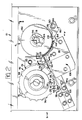
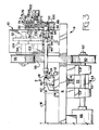
- the pin rolling apparatus comprises a wire feed station 2, a wire severing station 3, and a pin blank rolling station 6, station 2 being mounted to a base plate 8 of a frame, generally referenced 9, of the apparatus and the stations 3 and 6 being mounted to a subframe 10 on the plate 8.
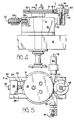
- the wheel 114 comprises, as best seen in Figure 8, two parts 126 and 128 which cooperate to define a peripheral groove 130 in which is seated a ring bearing 132 which extends about the whole periphery of the wheel 114 and to which is attached a resilient pin blank entraining ring 134, made for example of polyurethane.
- the peripheral forming surfaces 152 of the parts 126 and 128 are cylindrical and are thus coaxial with the axis of the shaft 118.
- the surfaces 152 provide pin rolling surfaces as will be described below.
- the ring 134 is freely rotatable on the bearing 132, about the axis of the shaft 118, independently of the wheel parts 126 and 128.
- each surface 144 defines in relation to the concave surface 140, an obtuse angle which progressively increases from the upper (as seen in Figure 7) end 146 of the surface 140, which end adjoins the track 110, towards the lower (as seen in Figure 7) end 148 of the surface 140 which provides the upper (as seen in Figure 7) edge of a vertical end face 150 of the block 116.
- the wheel 114 is supported over the block 116, by its shaft 118, with a portion of the circumference of the ring 134 opposite to and proximate to the surface 140 and with a portion of the circumference of each of the forming surfaces 152 opposite to and proximate to a respective one of the forming surfaces 144. As shown in Figures 9 and 10, the forming surfaces 114 diverge from each other towards the forming surfaces 152.
- the wheel 114 is stood on from the plate 82 by means of a spacer plate 153.
- a pin blank rolling wheel drag bar 154 has, at one end, an opening 156, through which the outer end of the shaft 118 rotatably extends, the other end of the bar 154 being pivoted to the plate 8 by means of an eccentric pivot pin 158 provided with a kerf, whereby the angular position of the pin 158 is adjustable, finely to adjust the spacing between the wheel 114 and the block 116.
- a pivot pin 160 Also secured to the plate 82 by means of a pivot pin 160 is a finished pin, bifurcated, stripper plate 162 ( Figure 2) having tapered fingers 164, the tips of which are urged towards the surfaces 152 by means of a spring 166 surrounding the pin 160.
- the motor 22 is operated to cause the wire W to be continuously driven through the guides 42 and 44 and the bushing 86, until its end abuts the stop plate 100, as best seen in Figure 6.
- the motor 66 is not operated.
- the wire shearing wheel 46 is rotated manually so that the teeth 76 of the wheel half 70, shear one pin blank PB, in turn, from the wire W, in cooperation with the bushing 86, the wire feed rolls 18 and 40 slipping on the wire W during each shearing operation.
- Each blank PB so sheared is held against the wheel 46 by the surface 98 of the pin hold down finger 92 and is carried by an opposed pair of teeth 76 of the wheel 48 onto the track 110, and is driven there along towards the station 6 by the next following pin blank PB sheared from the wire W.
- the shearing wheel 46 is rotated manually until the track 110 is fully occupied by a row of juxtaposed pin blanks PB, the blanks of the row adhering lightly to each other by virtue of the oil film that was applied to the wire W upstream of the wire guide 42.
- the motor 66 is actuated to rotate the wheels 46 and 114 under power, so that the row of blanks PB is driven towards the wheel 114 by one step each time the wheel 46 transfers a severed blank PB onto the track 110.
- each pin blank PB which is in the form of a right circular cylinder, as best seen in Figure 10
- reaches the upper end 146 of the concave surface 140 of the block 116 and thus becomes the leading blank of the row of blanks on the track 110
- said leading blank is forced by compressed air issuing from the nozzle 112, into an opposite groove 136 of the wheel 114, so as to be entrained ring 134.
- the wheel 114 rotates it passes the pin blank on to the concave surface 140, as shown in Figure 10 and between the surfaces 144, its entry there between being assisted by the wide angle guide mouth presented by the surfaces 144 at the end 146.
- Each pin that has been so formed falls from the end 148 of the surface 140, into a bin (not shown), assisted by the tips of the fingers 164 of the stripper plate 162.
- the ring 134 is rotatable relative to the remainder of the wheel 114 to take account of the difference between the velocity of the periphery of a pin blank PB as it rolls along the surface 140 and the velocity of the travel of the pin blank PB along the surface 140.
- the wheel 46 is rotated at such speed that no more than one pin blank PB at a time is presented to each groove 136.
- the clutch 102 will slip should any pin blank PB back-up in the track 110, for example, if for some reason a pin blank PB does not enter a groove 136 or the wheel 114 jams for some other reason.
Landscapes
- Engineering & Computer Science (AREA)
- Mechanical Engineering (AREA)
- Manufacturing & Machinery (AREA)
- Wire Processing (AREA)
- Manufacturing Of Electrical Connectors (AREA)
Applications Claiming Priority (2)
| Application Number | Priority Date | Filing Date | Title |
|---|---|---|---|
| BR8800864A BR8800864A (pt) | 1988-02-29 | 1988-02-29 | Aparelhos e processo para a fabricacao de pinos eletricos |
| BR8800864 | 1988-02-29 |
Publications (2)
| Publication Number | Publication Date |
|---|---|
| EP0331368A1 true EP0331368A1 (fr) | 1989-09-06 |
| EP0331368B1 EP0331368B1 (fr) | 1993-11-03 |
Family
ID=4044235
Family Applications (1)
| Application Number | Title | Priority Date | Filing Date |
|---|---|---|---|
| EP89301844A Expired - Lifetime EP0331368B1 (fr) | 1988-02-29 | 1989-02-24 | Fabrication de broches électriques |
Country Status (7)
| Country | Link |
|---|---|
| US (1) | US5031305A (fr) |
| EP (1) | EP0331368B1 (fr) |
| JP (1) | JPH01254336A (fr) |
| BR (1) | BR8800864A (fr) |
| DE (1) | DE68910347T2 (fr) |
| ES (1) | ES2045407T3 (fr) |
| PT (1) | PT89873B (fr) |
Cited By (1)
| Publication number | Priority date | Publication date | Assignee | Title |
|---|---|---|---|---|
| DE19541045A1 (de) * | 1995-11-03 | 1997-05-07 | Rudolf Goerlich | Verfahren und Vorrichtung zur Herstellung und zum Magazinieren von Kontaktstiften für elektrische Bauteile |
Families Citing this family (3)
| Publication number | Priority date | Publication date | Assignee | Title |
|---|---|---|---|---|
| US5611142A (en) * | 1995-06-06 | 1997-03-18 | Erico International Corporation | Method of making electrical connectors |
| US5608965A (en) * | 1995-06-06 | 1997-03-11 | Erico International Corporation | Method of making electrical connectors |
| US6171042B1 (en) | 1997-12-19 | 2001-01-09 | Illinois Tool Works Inc. | Hardened steel pin, pin and washer fastener, washer for fastener, and pin-making method |
Citations (2)
| Publication number | Priority date | Publication date | Assignee | Title |
|---|---|---|---|---|
| DE8709559U1 (de) * | 1987-07-10 | 1987-11-19 | Bausch & Patterer GmbH & Co KG, 8959 Roßhaupten | Vorrichtung zum Bearbeiten von Stiften, insbesondere von Computersteckstiften |
| EP0253753A2 (fr) * | 1986-07-14 | 1988-01-20 | Emerson Electric Co. | Méthode et appareil pour la fabrication d'une fiche d'un ensemble de borne hermétique |
Family Cites Families (6)
| Publication number | Priority date | Publication date | Assignee | Title |
|---|---|---|---|---|
| US1309523A (en) * | 1919-07-08 | hosford | ||
| US1632703A (en) * | 1921-12-22 | 1927-06-14 | Kenneth Alexander Roberts | Machine for manufacturing nails, brads, or the like from wire, rod, or the like |
| US3686912A (en) * | 1969-11-18 | 1972-08-29 | V Pk I Svarochnogo Proizv | Automatic rotary-swaging machine for reducing metal-wire parts |
| GB1580773A (en) * | 1977-03-01 | 1980-12-03 | Gen Staple Co | Apparatus for inserting terminal pins into a workpiece and supply strip therefor |
| JPS55147446A (en) * | 1979-05-02 | 1980-11-17 | Nippon Gakki Seizo Kk | Forming method for end part of pin |
| US4836006A (en) * | 1987-12-30 | 1989-06-06 | Brown Maurice H | Terminal forming apparatus |
-
1988
- 1988-02-29 BR BR8800864A patent/BR8800864A/pt not_active IP Right Cessation
-
1989
- 1989-02-02 US US07/305,874 patent/US5031305A/en not_active Expired - Lifetime
- 1989-02-24 ES ES89301844T patent/ES2045407T3/es not_active Expired - Fee Related
- 1989-02-24 EP EP89301844A patent/EP0331368B1/fr not_active Expired - Lifetime
- 1989-02-24 DE DE89301844T patent/DE68910347T2/de not_active Expired - Fee Related
- 1989-02-28 JP JP1048385A patent/JPH01254336A/ja active Pending
- 1989-02-28 PT PT89873A patent/PT89873B/pt not_active IP Right Cessation
Patent Citations (2)
| Publication number | Priority date | Publication date | Assignee | Title |
|---|---|---|---|---|
| EP0253753A2 (fr) * | 1986-07-14 | 1988-01-20 | Emerson Electric Co. | Méthode et appareil pour la fabrication d'une fiche d'un ensemble de borne hermétique |
| DE8709559U1 (de) * | 1987-07-10 | 1987-11-19 | Bausch & Patterer GmbH & Co KG, 8959 Roßhaupten | Vorrichtung zum Bearbeiten von Stiften, insbesondere von Computersteckstiften |
Cited By (1)
| Publication number | Priority date | Publication date | Assignee | Title |
|---|---|---|---|---|
| DE19541045A1 (de) * | 1995-11-03 | 1997-05-07 | Rudolf Goerlich | Verfahren und Vorrichtung zur Herstellung und zum Magazinieren von Kontaktstiften für elektrische Bauteile |
Also Published As
| Publication number | Publication date |
|---|---|
| EP0331368B1 (fr) | 1993-11-03 |
| BR8800864A (pt) | 1989-09-26 |
| DE68910347T2 (de) | 1994-05-11 |
| DE68910347D1 (de) | 1993-12-09 |
| US5031305A (en) | 1991-07-16 |
| ES2045407T3 (es) | 1994-01-16 |
| JPH01254336A (ja) | 1989-10-11 |
| PT89873A (pt) | 1989-10-04 |
| PT89873B (pt) | 1994-03-31 |
Similar Documents
| Publication | Publication Date | Title |
|---|---|---|
| DE69609687T2 (de) | Verfahren zur Herstellung eines Befestigungselements mit an einem Gewinde versehenen Nuten | |
| EP0312877A2 (fr) | Procédé et dispositif pour fabriquer et convoyer des coupes pour paquets | |
| EP0331368B1 (fr) | Fabrication de broches électriques | |
| CN115041923B (zh) | 一种开缝衬套的加工方法 | |
| EP0078775B1 (fr) | Machine à tronçonner et refouler à froid un matériau en fil | |
| US2949136A (en) | Apparatus for the automatic production of closed loops of wire from wire stock | |
| US2370702A (en) | Machine for crimping sheet metal | |
| US3650012A (en) | Process and apparatus for recovering metals from cables | |
| US2642593A (en) | Method and machine for assembling washers with fasteners | |
| CN116571660B (zh) | 一种金属线材调直切割机 | |
| US4663955A (en) | Apparatus for straightening tubing | |
| US4276796A (en) | Apparatus for cutting to length the connecting wires of electrical components | |
| JPH05201612A (ja) | ワイヤ選択および供給装置 | |
| US3604034A (en) | Method and apparatus for making nails with flat circular heads | |
| US4472956A (en) | Apparatus for feeding elongated objects | |
| US2582062A (en) | Machine for making spring dowel pins | |
| US4633919A (en) | Machine for cutting, bending and forming axial lead components | |
| CN111975156B (zh) | 一种剖锡装置及应用该剖锡装置的自动焊锡机 | |
| EP0803311A2 (fr) | Procédé et dispositif pour souder des viroles | |
| KR930003626B1 (ko) | 시이트 펀칭에 있어 시이트의 진행 이송장치 | |
| CN212124234U (zh) | 一种穿管机构及自动穿管装置 | |
| US1740612A (en) | Machine for twisting metal strips | |
| US2716760A (en) | Method and machine for assembling washers with rotary fasteners | |
| US20060048557A1 (en) | Method and device for bending blade member | |
| US2612912A (en) | Machine for straightening and cutting wire |
Legal Events
| Date | Code | Title | Description |
|---|---|---|---|
| PUAI | Public reference made under article 153(3) epc to a published international application that has entered the european phase |
Free format text: ORIGINAL CODE: 0009012 |
|
| AK | Designated contracting states |
Kind code of ref document: A1 Designated state(s): DE ES FR GB IT NL |
|
| RAP1 | Party data changed (applicant data changed or rights of an application transferred) |
Owner name: AMP INCORPORATED |
|
| 17P | Request for examination filed |
Effective date: 19900205 |
|
| 17Q | First examination report despatched |
Effective date: 19921117 |
|
| RAP1 | Party data changed (applicant data changed or rights of an application transferred) |
Owner name: THE WHITAKER CORPORATION |
|
| GRAA | (expected) grant |
Free format text: ORIGINAL CODE: 0009210 |
|
| AK | Designated contracting states |
Kind code of ref document: B1 Designated state(s): DE ES FR GB IT NL |
|
| REF | Corresponds to: |
Ref document number: 68910347 Country of ref document: DE Date of ref document: 19931209 |
|
| ET | Fr: translation filed | ||
| REG | Reference to a national code |
Ref country code: ES Ref legal event code: FG2A Ref document number: 2045407 Country of ref document: ES Kind code of ref document: T3 |
|
| ITF | It: translation for a ep patent filed | ||
| PLBE | No opposition filed within time limit |
Free format text: ORIGINAL CODE: 0009261 |
|
| STAA | Information on the status of an ep patent application or granted ep patent |
Free format text: STATUS: NO OPPOSITION FILED WITHIN TIME LIMIT |
|
| 26N | No opposition filed | ||
| PGFP | Annual fee paid to national office [announced via postgrant information from national office to epo] |
Ref country code: GB Payment date: 19980108 Year of fee payment: 10 |
|
| PGFP | Annual fee paid to national office [announced via postgrant information from national office to epo] |
Ref country code: FR Payment date: 19980209 Year of fee payment: 10 |
|
| PGFP | Annual fee paid to national office [announced via postgrant information from national office to epo] |
Ref country code: ES Payment date: 19980218 Year of fee payment: 10 |
|
| PGFP | Annual fee paid to national office [announced via postgrant information from national office to epo] |
Ref country code: NL Payment date: 19981222 Year of fee payment: 11 |
|
| PG25 | Lapsed in a contracting state [announced via postgrant information from national office to epo] |
Ref country code: GB Free format text: LAPSE BECAUSE OF NON-PAYMENT OF DUE FEES Effective date: 19990224 |
|
| PG25 | Lapsed in a contracting state [announced via postgrant information from national office to epo] |
Ref country code: ES Free format text: LAPSE BECAUSE OF NON-PAYMENT OF DUE FEES Effective date: 19990225 |
|
| PGFP | Annual fee paid to national office [announced via postgrant information from national office to epo] |
Ref country code: DE Payment date: 19990226 Year of fee payment: 11 |
|
| GBPC | Gb: european patent ceased through non-payment of renewal fee |
Effective date: 19990224 |
|
| PG25 | Lapsed in a contracting state [announced via postgrant information from national office to epo] |
Ref country code: FR Free format text: LAPSE BECAUSE OF NON-PAYMENT OF DUE FEES Effective date: 19991029 |
|
| REG | Reference to a national code |
Ref country code: FR Ref legal event code: ST |
|
| PG25 | Lapsed in a contracting state [announced via postgrant information from national office to epo] |
Ref country code: NL Free format text: LAPSE BECAUSE OF NON-PAYMENT OF DUE FEES Effective date: 20000901 |
|
| NLV4 | Nl: lapsed or anulled due to non-payment of the annual fee |
Effective date: 20000901 |
|
| PG25 | Lapsed in a contracting state [announced via postgrant information from national office to epo] |
Ref country code: DE Free format text: LAPSE BECAUSE OF NON-PAYMENT OF DUE FEES Effective date: 20001201 |
|
| REG | Reference to a national code |
Ref country code: ES Ref legal event code: FD2A Effective date: 20010910 |
|
| PG25 | Lapsed in a contracting state [announced via postgrant information from national office to epo] |
Ref country code: IT Free format text: LAPSE BECAUSE OF NON-PAYMENT OF DUE FEES Effective date: 20050224 |