EP0331403A1 - Befestigungsvorrichtung einer optischen Faser - Google Patents
Befestigungsvorrichtung einer optischen Faser Download PDFInfo
- Publication number
- EP0331403A1 EP0331403A1 EP89301940A EP89301940A EP0331403A1 EP 0331403 A1 EP0331403 A1 EP 0331403A1 EP 89301940 A EP89301940 A EP 89301940A EP 89301940 A EP89301940 A EP 89301940A EP 0331403 A1 EP0331403 A1 EP 0331403A1
- Authority
- EP
- European Patent Office
- Prior art keywords
- fibre
- optical fibre
- locating apparatus
- block
- groove
- Prior art date
- Legal status (The legal status is an assumption and is not a legal conclusion. Google has not performed a legal analysis and makes no representation as to the accuracy of the status listed.)
- Granted
Links
Images
Classifications
-
- G—PHYSICS
- G02—OPTICS
- G02B—OPTICAL ELEMENTS, SYSTEMS OR APPARATUS
- G02B6/00—Light guides; Structural details of arrangements comprising light guides and other optical elements, e.g. couplings
- G02B6/24—Coupling light guides
- G02B6/36—Mechanical coupling means
- G02B6/3628—Mechanical coupling means for mounting fibres to supporting carriers
- G02B6/3648—Supporting carriers of a microbench type, i.e. with micromachined additional mechanical structures
- G02B6/3652—Supporting carriers of a microbench type, i.e. with micromachined additional mechanical structures the additional structures being prepositioning mounting areas, allowing only movement in one dimension, e.g. grooves, trenches or vias in the microbench surface, i.e. self aligning supporting carriers
Definitions
- the present invention relates to optical fibre locating apparatus and in particular to such apparatus for locating an optical fibre with respect to a planar surface.
- optical fibre locating apparatus comprising first block means having a guide surface which includes a longitudinal 'V' groove adapted to receive and guide an optical fibre, a second block means having a facing surface perpendicular to the guide surface, the second block means including an aperture through which an end of an optical fibre may pass, and mounting means adapted to support apparatus presenting a planar surface whereby contacting the facing surface with such planar surface and feeding a fibre along the 'V' groove facilitates alignment of an end of such fibre with such planar surface.
- each of the block means comprises a silica block.
- the mounting means may comprise a further block having a 'V' shaped channel adapted to receive a slide in block having a signal receiving planar surface.
- the V shaped channel may be offset with respect to the aperture whereby the signal receiving point of the planar surface may be varied.
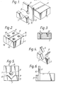
- the support comprises three accurately machined silica blocks 1, 2 and 3 which are glued together using ultra violet cured adhesive.
- the fibre support block 1 includes an accurate 'V' groove 4 which acts as a fibre guide. To ensure accuracy of the 'V' groove 4, particularly in regard to the angle at the base of the 'V' this block is in practice machined from two blocks which are subsequently glued together in the manner described in our European Patent Application No 86302785.0 (Publication No 200414).
- the block 1 is approximately twenty millimetres wide, twenty millimetres long and ten millimetres deep, the 'V' groove running along the centre line of the block and having an upper width of 0.177 millimetres.
- the facing block 2 approximately twenty millimetres deep and two millimetres long has a four millimetre aperture 5 drilled through centred on the centrelines of the vertical face.
- a one millimetre wide channel 6 is provided to facilitate entry of a fibre end (not shown) through the aperture 5.
- the mounting block 3 approximately seven millimetres deep and four millimetres long includes a 'V' shaped channel 7 which is arranged to receive either circular or rectangular mirrors or cover slides commonly used in fibre laser or amplifier systems for laboratory use.
- the block 3 is machined to provide a 'V' groove centred on the centre line and having a width at the upper end of 12.06 millimetres and at an angle to the vertical of 45 degrees.
- the block is completed by using silica inserts 8 and 9 which are glued in position the block 9 being two millimetres thick and the block 8 one millimetre thick.
- the 'V' groove is shifted off centre with respect to the groove 4 so that if for example a circular mirror is used then rotating same in the channel 7 results in a different portion of the receiving surface being presented.
- the forward face 10 of the block 2 is lapped and polished to ensure that it is precisely perpendicular to the 'V' groove A.
- a mirror or other planar receiving surface
- the surface 10 is precisely perpendicular to the v groove 4 a fibre edged forward along the groove in the direction of the mirror using a single advancing micrometer for example will abut the planar surface as accurately as the perpendicularity of the cleaving of the end of the fibre.
- Optical fibre has sufficient resilience to permit slight over advancement (i.e. causing the fibre to bend slightly on abutment) the fibre readily returning to alignment when withdrawn slightly.
- Index matching fluid may be used on the fibre end if necessary to cater for any slight deviation from the perpendicularity of the cleaver.
- the block 1 may be provided with apertures 11 to enable screw mounting of the support assembly to another surface.
- the apertures 11 include a countersunk section so that if screws are used the head comes below the surface to avoid accidental breakage of fibres by snagging.
- a further pair of apertures 12, one on each side of the 'V' groove 4 are also provided. These apertures 12 each receive an insert of magnetic stainless steel. This enables retention of a fibre in position by use of a flexible magnetic strip which may be laid over the fibre and 'V' groove 4.
- the apparatus is manufactured of silica other materials (e.g. aluminium) could be used.
- silica e.g. aluminium
- One advantage of silica is that thermal expansion effects on optical fibres are less likely to cause a system to move out of adjustment if the thermal co-efficients of the mounting and the fibre are compatible.
- silica block is noted particularly in laboratories in that in the event of stray laser light striking the block it will be scattered rather than reflected, thus reducing (as may occur with metallic blocks) the likelihood of accidental eye damage in persons working in such environments.
Landscapes
- Physics & Mathematics (AREA)
- Chemical & Material Sciences (AREA)
- Crystallography & Structural Chemistry (AREA)
- General Physics & Mathematics (AREA)
- Optics & Photonics (AREA)
- Mechanical Coupling Of Light Guides (AREA)
- Optical Couplings Of Light Guides (AREA)
- Laser Surgery Devices (AREA)
Priority Applications (1)
| Application Number | Priority Date | Filing Date | Title |
|---|---|---|---|
| AT89301940T ATE103716T1 (de) | 1988-03-02 | 1989-02-27 | Befestigungsvorrichtung einer optischen faser. |
Applications Claiming Priority (2)
| Application Number | Priority Date | Filing Date | Title |
|---|---|---|---|
| GB888805015A GB8805015D0 (en) | 1988-03-02 | 1988-03-02 | Optical fibre locating apparatus |
| GB8805015 | 1988-03-02 |
Publications (2)
| Publication Number | Publication Date |
|---|---|
| EP0331403A1 true EP0331403A1 (de) | 1989-09-06 |
| EP0331403B1 EP0331403B1 (de) | 1994-03-30 |
Family
ID=10632742
Family Applications (1)
| Application Number | Title | Priority Date | Filing Date |
|---|---|---|---|
| EP89301940A Expired - Lifetime EP0331403B1 (de) | 1988-03-02 | 1989-02-27 | Befestigungsvorrichtung einer optischen Faser |
Country Status (7)
| Country | Link |
|---|---|
| US (1) | US5029971A (de) |
| EP (1) | EP0331403B1 (de) |
| JP (1) | JPH03502613A (de) |
| AT (1) | ATE103716T1 (de) |
| DE (1) | DE68914181T2 (de) |
| GB (1) | GB8805015D0 (de) |
| WO (1) | WO1989008275A1 (de) |
Cited By (1)
| Publication number | Priority date | Publication date | Assignee | Title |
|---|---|---|---|---|
| WO2003065100A1 (en) * | 2002-01-29 | 2003-08-07 | Denselight Semiconductors Pte Ltd. | Package casing for fibre-coupled optoelectronic device |
Families Citing this family (5)
| Publication number | Priority date | Publication date | Assignee | Title |
|---|---|---|---|---|
| DE4240266A1 (de) * | 1992-12-01 | 1994-06-09 | Bosch Gmbh Robert | Verfahren zur Herstellung optischer Polymerbauelemente mit integrierten vertikalen Koppelstrukturen |
| GB2293248B (en) * | 1994-09-07 | 1998-02-18 | Northern Telecom Ltd | Providing optical coupling between optical components |
| US6074103A (en) * | 1996-10-15 | 2000-06-13 | Sdl, Inc. | Aligning an optical fiber with electroluminescent semiconductor diodes and other optical components |
| US7331403B2 (en) * | 2004-04-02 | 2008-02-19 | Black & Decker Inc. | Lock-out for activation arm mechanism in a power tool |
| US9935218B2 (en) | 2015-01-02 | 2018-04-03 | BAE Systems Information and Electronic Systems Integreation Inc. | Generation of flexible high power pulsed waveforms |
Citations (2)
| Publication number | Priority date | Publication date | Assignee | Title |
|---|---|---|---|---|
| FR2311325A1 (fr) * | 1975-05-14 | 1976-12-10 | Philips Nv | Dispositif pour coupler une source lumineuse a une fibre optique |
| WO1987002474A1 (en) * | 1985-10-16 | 1987-04-23 | British Telecommunications Public Limited Company | Positioning optical components and waveguides |
Family Cites Families (10)
| Publication number | Priority date | Publication date | Assignee | Title |
|---|---|---|---|---|
| FR2305746A1 (fr) * | 1975-03-25 | 1976-10-22 | Trt Telecom Radio Electr | Connecteur pour fibres optiques |
| GB1577729A (en) * | 1976-09-25 | 1980-10-29 | Plessey Co Ltd | Coupling of optic-waveguide elements |
| FR2440562A1 (fr) * | 1978-10-31 | 1980-05-30 | Socapex | Dispositif de centrage d'une fibre optique dans un embout, et embout realise au moyen de ce dispositif |
| JPS5821890A (ja) * | 1981-08-03 | 1983-02-08 | Nippon Telegr & Teleph Corp <Ntt> | 半導体レ−ザと光フアイバとの結合装置 |
| JPS5918416U (ja) * | 1982-07-28 | 1984-02-04 | パイオニア株式会社 | トランス |
| FR2546311B1 (fr) * | 1983-05-17 | 1986-03-28 | France Etat | Procede et dispositif de connexion entre une fibre optique et un composant d'optique integree comportant un guide d'onde |
| US4714315A (en) * | 1984-10-24 | 1987-12-22 | Siemens Aktiengesellschaft | Method for connecting elements of optical communication technology to one another or to elements of releasable plug connections |
| US4966433A (en) * | 1988-03-03 | 1990-10-30 | At&T Bell Laboratories | Device including a component in alignment with a substrate-supported waveguide |
| US4916497A (en) * | 1988-05-18 | 1990-04-10 | Harris Corporation | Integrated circuits including photo-optical devices and pressure transducers and method of fabrication |
| EP0361153A3 (de) * | 1988-09-29 | 1991-07-24 | Siemens Aktiengesellschaft | Anordnung zum Koppeln einer optischen Faser an ein Koppelfenster eines planar integriert optischen Bauteils und Verfahren zur Herstellung einer solchen Anordnung |
-
1988
- 1988-03-02 GB GB888805015A patent/GB8805015D0/en active Pending
-
1989
- 1989-02-27 WO PCT/GB1989/000203 patent/WO1989008275A1/en not_active Ceased
- 1989-02-27 DE DE68914181T patent/DE68914181T2/de not_active Expired - Fee Related
- 1989-02-27 AT AT89301940T patent/ATE103716T1/de not_active IP Right Cessation
- 1989-02-27 EP EP89301940A patent/EP0331403B1/de not_active Expired - Lifetime
- 1989-02-27 US US07/469,484 patent/US5029971A/en not_active Expired - Fee Related
- 1989-02-27 JP JP1503233A patent/JPH03502613A/ja active Pending
Patent Citations (3)
| Publication number | Priority date | Publication date | Assignee | Title |
|---|---|---|---|---|
| FR2311325A1 (fr) * | 1975-05-14 | 1976-12-10 | Philips Nv | Dispositif pour coupler une source lumineuse a une fibre optique |
| WO1987002474A1 (en) * | 1985-10-16 | 1987-04-23 | British Telecommunications Public Limited Company | Positioning optical components and waveguides |
| WO1987002518A1 (en) * | 1985-10-16 | 1987-04-23 | British Telecommunications Public Limited Company | Mounting a component to a substrate |
Non-Patent Citations (2)
| Title |
|---|
| IBM TECHNICAL DISCLOSURE BULLETIN, vol. 25, no. 8, January 1983, pages 4261,4262, New York, US; L. BALLIET et al.: "Coined precision mount for fiber-optic driver/receiver surface diodes" * |
| PATENT ABSTRACTS OF JAPAN, vol. 7, no. 99 (E-172)[1244], 27th April 1983; & JP-A-58 21 890 (NIPPON DENSHIN DENWA KOSHA) 08-02-1983 * |
Cited By (1)
| Publication number | Priority date | Publication date | Assignee | Title |
|---|---|---|---|---|
| WO2003065100A1 (en) * | 2002-01-29 | 2003-08-07 | Denselight Semiconductors Pte Ltd. | Package casing for fibre-coupled optoelectronic device |
Also Published As
| Publication number | Publication date |
|---|---|
| JPH03502613A (ja) | 1991-06-13 |
| GB8805015D0 (en) | 1988-03-30 |
| WO1989008275A1 (en) | 1989-09-08 |
| EP0331403B1 (de) | 1994-03-30 |
| DE68914181D1 (de) | 1994-05-05 |
| DE68914181T2 (de) | 1994-07-14 |
| ATE103716T1 (de) | 1994-04-15 |
| US5029971A (en) | 1991-07-09 |
Similar Documents
| Publication | Publication Date | Title |
|---|---|---|
| US5121457A (en) | Method for coupling laser array to optical fiber array | |
| US5340371A (en) | Optical fiber splicing chuck | |
| US6668128B2 (en) | Optical fiber wire holder, fusion-splicing apparatus, cleaving apparatus, and optical fiber splicing method | |
| US9933571B2 (en) | Profiling of cleaved angled end faces of optical fiber(s) | |
| US4473942A (en) | Precision cleaving of optical fibers | |
| US4439005A (en) | Branching element for optical waveguides | |
| US5029971A (en) | Optical fibre locating apparatus | |
| JPH0843667A (ja) | 光ファイバを基質に形成された導波管に連結する装置 | |
| NZ203158A (en) | Joining optical fibre ends:clamping in axial alignment and fusing | |
| CN101556354B (zh) | 现场端接方法和装置 | |
| US7669744B2 (en) | Device and method for cleaving optical fibers | |
| US20050013579A1 (en) | Method and apparatus for inspecting end surfaces on optical connectors | |
| WO2002073121A2 (en) | Fiber collimator | |
| US9753225B2 (en) | Passive alignment optical connector | |
| US11280963B2 (en) | Optical fiber clamp | |
| CA1141212A (en) | Device for centering an optical fiber within a terminal, and a terminal constructed by means of said device | |
| EP0226274A2 (de) | Mehrfachanordnung von optischen Fasern in optischen Steckern | |
| US5787216A (en) | Fiber splicing assembly | |
| CN109270632B (zh) | 一种光纤干涉仪制作装置及方法 | |
| JPH05134135A (ja) | 光導波路基板と光フアイバホルダとの接続方法 | |
| US10288809B1 (en) | Optical fiber laser cleaver adapter | |
| JP3256533B2 (ja) | 光スイッチ | |
| JP3026477B2 (ja) | 光導波路基板 | |
| CN110709742A (zh) | 带透镜的光纤的制造方法、以及切断装置 | |
| US4946248A (en) | Connection end of a light waveguide bonded to a holder |
Legal Events
| Date | Code | Title | Description |
|---|---|---|---|
| PUAI | Public reference made under article 153(3) epc to a published international application that has entered the european phase |
Free format text: ORIGINAL CODE: 0009012 |
|
| AK | Designated contracting states |
Kind code of ref document: A1 Designated state(s): AT BE CH DE ES FR GB GR IT LI LU NL SE |
|
| 17P | Request for examination filed |
Effective date: 19900208 |
|
| 17Q | First examination report despatched |
Effective date: 19911121 |
|
| GRAA | (expected) grant |
Free format text: ORIGINAL CODE: 0009210 |
|
| AK | Designated contracting states |
Kind code of ref document: B1 Designated state(s): AT BE CH DE ES FR GB GR IT LI LU NL SE |
|
| PG25 | Lapsed in a contracting state [announced via postgrant information from national office to epo] |
Ref country code: SE Free format text: THE PATENT HAS BEEN ANNULLED BY A DECISION OF A NATIONAL AUTHORITY Effective date: 19940330 Ref country code: LI Effective date: 19940330 Ref country code: GR Free format text: LAPSE BECAUSE OF FAILURE TO SUBMIT A TRANSLATION OF THE DESCRIPTION OR TO PAY THE FEE WITHIN THE PRESCRIBED TIME-LIMIT Effective date: 19940330 Ref country code: ES Free format text: THE PATENT HAS BEEN ANNULLED BY A DECISION OF A NATIONAL AUTHORITY Effective date: 19940330 Ref country code: CH Effective date: 19940330 Ref country code: BE Effective date: 19940330 Ref country code: AT Effective date: 19940330 |
|
| REF | Corresponds to: |
Ref document number: 103716 Country of ref document: AT Date of ref document: 19940415 Kind code of ref document: T |
|
| ITF | It: translation for a ep patent filed | ||
| REF | Corresponds to: |
Ref document number: 68914181 Country of ref document: DE Date of ref document: 19940505 |
|
| REG | Reference to a national code |
Ref country code: CH Ref legal event code: PL |
|
| ET | Fr: translation filed | ||
| PLBE | No opposition filed within time limit |
Free format text: ORIGINAL CODE: 0009261 |
|
| STAA | Information on the status of an ep patent application or granted ep patent |
Free format text: STATUS: NO OPPOSITION FILED WITHIN TIME LIMIT |
|
| PG25 | Lapsed in a contracting state [announced via postgrant information from national office to epo] |
Ref country code: GB Effective date: 19950227 |
|
| PG25 | Lapsed in a contracting state [announced via postgrant information from national office to epo] |
Ref country code: LU Free format text: LAPSE BECAUSE OF NON-PAYMENT OF DUE FEES Effective date: 19950228 |
|
| 26N | No opposition filed | ||
| PG25 | Lapsed in a contracting state [announced via postgrant information from national office to epo] |
Ref country code: NL Effective date: 19950901 |
|
| GBPC | Gb: european patent ceased through non-payment of renewal fee |
Effective date: 19950227 |
|
| PG25 | Lapsed in a contracting state [announced via postgrant information from national office to epo] |
Ref country code: FR Effective date: 19951031 |
|
| NLV4 | Nl: lapsed or anulled due to non-payment of the annual fee |
Effective date: 19950901 |
|
| PG25 | Lapsed in a contracting state [announced via postgrant information from national office to epo] |
Ref country code: DE Effective date: 19951101 |
|
| REG | Reference to a national code |
Ref country code: FR Ref legal event code: ST |
|
| PG25 | Lapsed in a contracting state [announced via postgrant information from national office to epo] |
Ref country code: IT Free format text: LAPSE BECAUSE OF NON-PAYMENT OF DUE FEES;WARNING: LAPSES OF ITALIAN PATENTS WITH EFFECTIVE DATE BEFORE 2007 MAY HAVE OCCURRED AT ANY TIME BEFORE 2007. THE CORRECT EFFECTIVE DATE MAY BE DIFFERENT FROM THE ONE RECORDED. Effective date: 20050227 |