EP0331579A1 - Formschlussverbindung zwischen Pfeilgeschoss und Treibkäfig - Google Patents
Formschlussverbindung zwischen Pfeilgeschoss und Treibkäfig Download PDFInfo
- Publication number
- EP0331579A1 EP0331579A1 EP89400575A EP89400575A EP0331579A1 EP 0331579 A1 EP0331579 A1 EP 0331579A1 EP 89400575 A EP89400575 A EP 89400575A EP 89400575 A EP89400575 A EP 89400575A EP 0331579 A1 EP0331579 A1 EP 0331579A1
- Authority
- EP
- European Patent Office
- Prior art keywords
- indenter
- shoe
- stop
- tooth
- average temperature
- Prior art date
- Legal status (The legal status is an assumption and is not a legal conclusion. Google has not performed a legal analysis and makes no representation as to the accuracy of the status listed.)
- Granted
Links
Images

Classifications
-
- F—MECHANICAL ENGINEERING; LIGHTING; HEATING; WEAPONS; BLASTING
- F42—AMMUNITION; BLASTING
- F42B—EXPLOSIVE CHARGES, e.g. FOR BLASTING, FIREWORKS, AMMUNITION
- F42B14/00—Projectiles or missiles characterised by arrangements for guiding or sealing them inside barrels, or for lubricating or cleaning barrels
- F42B14/06—Sub-calibre projectiles having sabots; Sabots therefor
- F42B14/061—Sabots for long rod fin stabilised kinetic energy projectiles, i.e. multisegment sabots attached midway on the projectile
-
- F—MECHANICAL ENGINEERING; LIGHTING; HEATING; WEAPONS; BLASTING
- F42—AMMUNITION; BLASTING
- F42B—EXPLOSIVE CHARGES, e.g. FOR BLASTING, FIREWORKS, AMMUNITION
- F42B14/00—Projectiles or missiles characterised by arrangements for guiding or sealing them inside barrels, or for lubricating or cleaning barrels
- F42B14/06—Sub-calibre projectiles having sabots; Sabots therefor
- F42B14/061—Sabots for long rod fin stabilised kinetic energy projectiles, i.e. multisegment sabots attached midway on the projectile
- F42B14/062—Sabots for long rod fin stabilised kinetic energy projectiles, i.e. multisegment sabots attached midway on the projectile characterised by contact surfaces between projectile and sabot
-
- F—MECHANICAL ENGINEERING; LIGHTING; HEATING; WEAPONS; BLASTING
- F42—AMMUNITION; BLASTING
- F42B—EXPLOSIVE CHARGES, e.g. FOR BLASTING, FIREWORKS, AMMUNITION
- F42B14/00—Projectiles or missiles characterised by arrangements for guiding or sealing them inside barrels, or for lubricating or cleaning barrels
- F42B14/06—Sub-calibre projectiles having sabots; Sabots therefor
- F42B14/068—Sabots characterised by the material
Definitions
- the present invention relates to a form-matching connection device between an arrow type penetrator and a shoe.
- the field of application of the invention is that of kinetic energy projectiles of the arrow type for artillery ammunition.
- the launch shoe drives the penetrator during the interior ballistics phase, and releases it at the exit of the weapon. It is necessary to define the means of connection between the hoof and the indenter. Indeed, these must be strong enough to drive the penetrator but must not prevent its release by the shoe, and they must also ensure precise positioning between the penetrator and the shoe, in order to ensure good reproducibility of the ballistic characteristics.
- US Pat. No. 3,148,472 describes a plastic shoe completely surrounding the indenter and driving it by means of annular toothed profiles. Such a shoe drives the penetrator so well that it is difficult to cause the separation of these elements at the exit of the weapon.
- the cited patent thus proposes to have, inside the barrel of the weapon, cutting profiles such as to weaken the hoof, which then facilitates separation.
- connection means consisting of several annular teeth, the clearance between the teeth of the indenter and their housing in the shoe being sufficiently reduced to avoid any displacement of too great a magnitude, or even by performing a connection by thread, a fixed stop ensuring the final relative position at the end of the screwing of the indenter.
- the latter method is particularly interesting from the manufacturing point of view.
- the object of the present invention is to propose a device for form-matching connection between a penetrator and a shoe made up of several sectors which makes it possible to ensure operation at the extreme temperatures of use of a munition while assembling the components. is carried out at a medium temperature.
- the subject of the invention is a connecting device by shape concordance between an arrow type penetrator of heavy material and a shoe of light material made up of several sectors, the shoe and the penetrator, components of a munition, being positioned relative to each other by means of an axial stop, device comprising a first profile carried by the indenter and a second profile carried by the shoe, the profiles having, in section along an axial plane, a form of teeth, each tooth having a first and a second flank and the first flank being situated on the side of the stop, characterized in that in the assembled configuration, there is a relative axial clearance between the first and the second, profile whose total value , at the movenne temperature of assembly of the indenter and the shoe, determined between the indenter's tooth furthest from the stop and its corresponding housing in the shoe is at least equal to product of the distance between the stop and the second flank of the indenter's tooth farthest from it by the difference in the expansion coefficients of the materials constituting the shoe
- the stop is constituted by a disc integral with the indenter or the shoe and made of a material whose compressibility at maximum and minimum temperatures is such that the force required to compress this disc is less than that which, exerted axially on the indenter, would make it possible to separate the different sectors, the clearances between the different teeth of the indenter and their respective housings in the shoe being advantageously all equal.
- the first and the second profile are such that the total value of the clearance, at the average temperature, between each tooth and its housing in the shoe varies linearly and increasing between the stop and the most tooth remote from the latter, the abutment can be constituted by a shoulder secured to the indenter.
- the profiles constituting the form-matching connection device can be circular members or threads.
- the thread carried by the indenter is such that the first flanks of the teeth are carried by a first propeller and the second flanks are carried by a second propeller, the steps of the two propellers being different, the pitch of the first propeller being greater than the pitch of the shoe thread which is itself greater than the pitch of the second propeller.
- the total value of the clearance, at the average temperature, between the indenter's tooth furthest from the stop and its corresponding housing in the shoe is at least equal to the product of the distance between the stop and said housing, by the difference in the expansion coefficients of the materials constituting the shoe and the indenter and by the difference between the maximum and minimum temperatures.
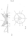
- a known arrow type projectile is constituted by a penetrator 1 surrounded by a shoe 2, constituted by three sectors 3, 4, 5 intended to separate from each other at the exit of the weapon under the effect of aerodynamic forces and thus release the penetrator.
- Shoe and indenter are made integral with each other by a form-matching connection device, which is constituted by a first profile 7 carried by the indenter and a second profile 8 carried by the shoe.
- a stop 6 is provided.
- this stop is a shoulder of the indenter; assembly is carried out by screwing the indenter into the shoe, the three sectors being secured by belts 12, 13, until contact with the stop 6 therewith.
- the assembly is carried out at an average temperature, for example of the order of 20 ° C; there is a functional clearance between the shoe and the indenter which allows screwing or assembly, the abutment ensuring the correct position.
- the materials have different coefficients of linear expansion (25 X 10 ⁇ 6 ° C ⁇ 1 for aluminum, 5 X 10 ⁇ 6 ° C ⁇ 1 for the commonly used tungsten alloy).
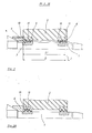
- FIG. 2 shows, at average temperature, a first embodiment of the connection device according to the invention.
- Profiles 7 and 8 are threads.
- the stop 6 is here constituted by a washer, integral with the penetrator at its rear part, for example by shape matching with the tail of the latter.
- the washer is made made of a material having a certain compressibility. The criteria for choosing and defining this compressibility are explained below.
- the assembly of the indenter is carried out at average temperature by screwing until contact with the stop 6 with the shoe 2.
- the final position is that shown in FIG. 2.
- the first flank is called 10 that which is oriented towards the stop 6, the latter is in contact with the shoe, while there remains a clearance J between the second flank 11 and the shoe.
- this clearance J has a value which is the same for all the teeth and which is chosen to be greater than or equal to the product of the distance D between the stop and the second flank of the indenter's tooth farthest from the latter. , by the difference ( ⁇ s- ⁇ p) of the coefficients of expansion of the materials constituting the shoe and the indenter and by the maximum value of the difference between the average temperature (To) and the maximum (Tmax) or minimum (Tmin) temperatures desired for the use of ammunition.
- the distance D is measured along a direction parallel to the axis of the indenter, for example situated at the level of the average height of the teeth, the clearances also being measured along this same axial direction.
- This theoretical limit value which involves the average mounting temperature can advantageously be replaced by a limit value involving only the extreme values of the temperature interval.
- We can thus choose a game such as: J ⁇ d. ( ⁇ s- ⁇ p) (Tmax-Tmin).
- the material constituting the stopper 6 is chosen so that, for all the temperatures between the average temperature and the desired maximum temperature, the force necessary to compress this stopper is less than that which, exerted axially on the indenter would allow spread the different sectors of the shoe by sliding the teeth thereof on those of the indenter. It can thus be seen that this choice depends on the amplitude of the expansion to be absorbed, therefore on the nature of the materials present and on the length of the threaded part, and that it also depends on the profile of the teeth as well as on the material constituting the belts 12 and 13.
- a polyethylene disc low density whose compressibility is of the order of 850 N / m2 both at 20 ° C and 60 ° C, and cooperating with a play of the order of 0.21 mm, has given complete satisfaction.
- the stop 6 no longer plays a role of fixed point but it cooperates with the play arranged between the profiles of the indenter and of the shoe so as to absorb the differential expansions of these two elements.
- the stop also acts as a brake by preventing the indenter from unscrewing.
- it may include a profile cooperating with the surface of the shoe with which it comes into contact.
- the stop 6 can also be secured to the shoe. In this case, it is arranged at the end of the shoe opposite to that by which the indenter is introduced during assembly, and a shoulder of the latter comes into contact with it.
- the indenter is in contact with the stop and the clearance is then located between the first flank of the teeth and their housing in the shoe.
- the stop is compressed during contractions of the hoof and the indenter, which occurs for any temperature below the average temperature, the expansions only causing a reduction in the clearance.
- the material constituting the stop is then chosen so that, for all the temperatures between the average temperature and the desired minimum temperature, the force necessary to compress it is less than that which, exerted axially on the indenter, would allow remove the different sectors of the hoof.
- FIG. 3 shows, at average temperature, a second embodiment of the connection device according to the invention.
- the profiles 7 and 8 are always threads, but the thread constituting the first profile 7 is such that the sides 10 and 11 of each tooth are carried by two propellers of different pitch.
- the first side 10 located on the side of the stop 6, is integral with a first propeller while the second side 11 is carried by a second propeller.
- the pitch of the first propeller is greater than the pitch of the shoe thread which is itself greater than the pitch of the second propeller.
- the total axial clearance (Jav1 + Jar1) between the tooth closest to the stop and its housing in the shoe is less than the total axial clearance (JavN + JarN) between the tooth furthest from the stop and its housing.
- the value of this clearance varies linearly and increasing from the nearest tooth to the tooth furthest from the stop.
- the products P1 and P2 respectively give the images of the maximum amplitudes, at the level of the last tooth, of the dilation and of the contraction.
- This method of calculation leads, after having determined the value of the maximum and minimum amplitudes of the differential expansions of the hoof and the indenter, to distribute them at the level of each thread tooth of the indenter.
- the pitch of the first propeller is then greater than the pitch of the shoe which is itself greater than the pitch of the second propeller. If, at the level of the indenter tooth closest to the stop, the total play is very small, this play will increase linearly until it reaches its maximum value at the level of the indentor tooth furthest from the stop.
- FIGS. 3A and 3b show the distribution of the different clearances for the maximum 3A and minimum 3b temperatures, it can be seen that, for the maximum temperature, all the first flanks 10 of the indenter teeth are in contact with the shoe, while, for the minimum temperature, these are all the second flanks which are in contact with it.
- the pitch of the first propeller is 2.502 and that of the second is 2.497.
- the maximum value of the play at the level of the indentor tooth furthest from the stop is then 0.392 mm.
- the mode of cooperation of the fixed stop with the profiles of the indenter and of the shoe is situated at the level of the different values of the distances between said stop and each of the teeth, the linear variation and increasing the total clearance as a function of this distance ensuring the absence of interference between the profiles.
- the pressure developed by a propellant charge depends on its operating temperature.
- the coefficient of variation of the pressure as a function of the temperature is of the order of 12 to 15 bars / ° C; therefore for a temperature range between -40 ° C and + 60 ° C, the total temperature variation is 100 ° C, which results in a possible total variation of the developed pressure from 1200 to 1500 bar.
- Such pressure variations are detrimental to good mechanical strength of the connecting device. It is then useful to have, for the maximum values of the pressure, a contact surface at the level of the connection device which is also maximum.
Landscapes
- General Engineering & Computer Science (AREA)
- Engineering & Computer Science (AREA)
- Footwear And Its Accessory, Manufacturing Method And Apparatuses (AREA)
- Ultra Sonic Daignosis Equipment (AREA)
- Load-Engaging Elements For Cranes (AREA)
- Portable Nailing Machines And Staplers (AREA)
- Pinball Game Machines (AREA)
- Centrifugal Separators (AREA)
- Refuse Collection And Transfer (AREA)
- Cage And Drive Apparatuses For Elevators (AREA)
- Measurement Of Velocity Or Position Using Acoustic Or Ultrasonic Waves (AREA)
- Aiming, Guidance, Guns With A Light Source, Armor, Camouflage, And Targets (AREA)
- Stringed Musical Instruments (AREA)
- Micro-Organisms Or Cultivation Processes Thereof (AREA)
- Braking Arrangements (AREA)
- Mutual Connection Of Rods And Tubes (AREA)
- Joining Of Building Structures In Genera (AREA)
- Soil Working Implements (AREA)
- Diaphragms For Electromechanical Transducers (AREA)
- Jib Cranes (AREA)
Priority Applications (1)
| Application Number | Priority Date | Filing Date | Title |
|---|---|---|---|
| AT89400575T ATE88008T1 (de) | 1988-03-03 | 1989-03-02 | Formschlussverbindung zwischen pfeilgeschoss und treibkaefig. |
Applications Claiming Priority (2)
| Application Number | Priority Date | Filing Date | Title |
|---|---|---|---|
| FR8802681 | 1988-03-03 | ||
| FR8802681A FR2628196B1 (fr) | 1988-03-03 | 1988-03-03 | Dispositif de liaison par concordance de forme entre un penetrateur de type fleche et un sabot |
Publications (2)
| Publication Number | Publication Date |
|---|---|
| EP0331579A1 true EP0331579A1 (de) | 1989-09-06 |
| EP0331579B1 EP0331579B1 (de) | 1993-04-07 |
Family
ID=9363866
Family Applications (1)
| Application Number | Title | Priority Date | Filing Date |
|---|---|---|---|
| EP89400575A Expired - Lifetime EP0331579B1 (de) | 1988-03-03 | 1989-03-02 | Formschlussverbindung zwischen Pfeilgeschoss und Treibkäfig |
Country Status (7)
| Country | Link |
|---|---|
| EP (1) | EP0331579B1 (de) |
| AT (1) | ATE88008T1 (de) |
| CA (1) | CA1334731C (de) |
| DE (1) | DE68905849T2 (de) |
| FR (1) | FR2628196B1 (de) |
| IL (1) | IL89457A (de) |
| NO (1) | NO169407C (de) |
Cited By (2)
| Publication number | Priority date | Publication date | Assignee | Title |
|---|---|---|---|---|
| FR2654506A1 (fr) * | 1989-11-11 | 1991-05-17 | Rheinmetall Gmbh | Ensemble de projectile sous-calibre. |
| FR2969747A1 (fr) * | 2010-12-23 | 2012-06-29 | Nexter Munitions | Penetrateur fleche chemise |
Families Citing this family (2)
| Publication number | Priority date | Publication date | Assignee | Title |
|---|---|---|---|---|
| FR2948185A1 (fr) | 2009-07-20 | 2011-01-21 | Nexter Munitions | Dispositif de liaison par concordance de forme entre un sabot et un barreau d'un projectile |
| DE102009050162A1 (de) * | 2009-10-21 | 2011-04-28 | TDW Gesellschaft für verteidigungstechnische Wirksysteme mbH | Dämpfungsvorrichtung für Einbauteile in Penetratoren |
Citations (6)
| Publication number | Priority date | Publication date | Assignee | Title |
|---|---|---|---|---|
| GB131034A (en) * | 1918-03-28 | 1919-08-21 | Leonard Godfrey Pinney Thring | Improvements in or relating to Subcalibre Projectiles. |
| US2996011A (en) * | 1944-06-30 | 1961-08-15 | Henry F Dunlap | Projectile |
| US3262391A (en) * | 1964-10-12 | 1966-07-26 | Budd Co | Subcaliber projectile and sabot |
| US3859922A (en) * | 1973-06-28 | 1975-01-14 | Us Army | Two piece ammunition round |
| US4469027A (en) * | 1983-04-15 | 1984-09-04 | The United States Of America As Represented By The Secretary Of The Army | Armor piercing ammunition having interlocking means |
| EP0137106A1 (de) * | 1983-07-20 | 1985-04-17 | Rheinmetall GmbH | Mantel für Treibkäfiggeschosse |
-
1988
- 1988-03-03 FR FR8802681A patent/FR2628196B1/fr not_active Expired - Lifetime
-
1989
- 1989-03-02 AT AT89400575T patent/ATE88008T1/de not_active IP Right Cessation
- 1989-03-02 CA CA000592641A patent/CA1334731C/fr not_active Expired - Fee Related
- 1989-03-02 IL IL89457A patent/IL89457A/xx not_active IP Right Cessation
- 1989-03-02 EP EP89400575A patent/EP0331579B1/de not_active Expired - Lifetime
- 1989-03-02 DE DE8989400575T patent/DE68905849T2/de not_active Expired - Fee Related
- 1989-03-02 NO NO890903A patent/NO169407C/no unknown
Patent Citations (6)
| Publication number | Priority date | Publication date | Assignee | Title |
|---|---|---|---|---|
| GB131034A (en) * | 1918-03-28 | 1919-08-21 | Leonard Godfrey Pinney Thring | Improvements in or relating to Subcalibre Projectiles. |
| US2996011A (en) * | 1944-06-30 | 1961-08-15 | Henry F Dunlap | Projectile |
| US3262391A (en) * | 1964-10-12 | 1966-07-26 | Budd Co | Subcaliber projectile and sabot |
| US3859922A (en) * | 1973-06-28 | 1975-01-14 | Us Army | Two piece ammunition round |
| US4469027A (en) * | 1983-04-15 | 1984-09-04 | The United States Of America As Represented By The Secretary Of The Army | Armor piercing ammunition having interlocking means |
| EP0137106A1 (de) * | 1983-07-20 | 1985-04-17 | Rheinmetall GmbH | Mantel für Treibkäfiggeschosse |
Cited By (2)
| Publication number | Priority date | Publication date | Assignee | Title |
|---|---|---|---|---|
| FR2654506A1 (fr) * | 1989-11-11 | 1991-05-17 | Rheinmetall Gmbh | Ensemble de projectile sous-calibre. |
| FR2969747A1 (fr) * | 2010-12-23 | 2012-06-29 | Nexter Munitions | Penetrateur fleche chemise |
Also Published As
| Publication number | Publication date |
|---|---|
| IL89457A0 (en) | 1989-09-10 |
| FR2628196B1 (fr) | 1990-07-06 |
| FR2628196A1 (fr) | 1989-09-08 |
| EP0331579B1 (de) | 1993-04-07 |
| ATE88008T1 (de) | 1993-04-15 |
| NO890903D0 (no) | 1989-03-02 |
| DE68905849D1 (de) | 1993-05-13 |
| NO890903L (no) | 1989-09-04 |
| CA1334731C (fr) | 1995-03-14 |
| NO169407B (no) | 1992-03-09 |
| DE68905849T2 (de) | 1993-08-26 |
| NO169407C (no) | 1992-06-17 |
| IL89457A (en) | 1991-11-21 |
Similar Documents
| Publication | Publication Date | Title |
|---|---|---|
| EP0666967B1 (de) | Dämpfer für ein mechanisches system | |
| EP0723131B1 (de) | Mündungsbremse für ein mittel- oder grosskalibriges Geschütz | |
| FR2526151A1 (fr) | Munition encartouchee constituee par un projectile et une douille combustible ou partiellement combustible reliee a celui-ci | |
| CH634142A5 (fr) | Mecanisme de lancement d'un projectile sous-calibre. | |
| EP0572643A1 (de) | Kugelfang fuer gewehrgranate mit kugelsplitterfangeinrichtung. | |
| EP0307307A1 (de) | Verbindungsring zwischen Geschoss und Geschosshülse | |
| EP0331579B1 (de) | Formschlussverbindung zwischen Pfeilgeschoss und Treibkäfig | |
| EP1445573A1 (de) | Treibkäfig für ein Unterkalibergeschoss | |
| FR2682754A1 (fr) | Obus cargo. | |
| EP0594482B1 (de) | Treibladungsbehälter | |
| EP0268535B1 (de) | Drehbarer Führungsring für Geschosse jeden Kalibers | |
| FR2702557A1 (fr) | Dispositif de calage pour sous-munition. | |
| FR2626359A1 (fr) | Projectile a cage de poussee, sous-calibre et stabilise par ailettes | |
| EP0401114B1 (de) | Vorrichtung zum Halten eines Geschosses in bezug auf das Gehäuse einer teleskopartigen Munition | |
| FR2665761A1 (fr) | Ceinture d'etancheite pour projectile fleche. | |
| FR2672673A1 (fr) | Dispositif d'amorcage pour un sous-projectile. | |
| FR2526153A1 (fr) | Projectile sous-calibre a sabot annulaire | |
| EP0354088B1 (de) | Vorrichtung zum Öffnen der Flügelschäfte eines Geschosses | |
| FR2665765A1 (fr) | Dispositif d'arret en rotation entre un barreau et un sabot. | |
| EP2278257B1 (de) | Unterkalibriges Geschoss umfassend einen Treibkäfig und einen Penetrator, die mittels formschlüssiger Verbindungsmittel verbunden sind, sowie ein in einem solchen Geschoss eingebauter Treibkäfig | |
| FR2721700A1 (fr) | Dispositif d'accélération destiné à accélérer un aérodyne. | |
| EP1693645A1 (de) | Mit einem Führungsband versehenes Artilleriegeschoss | |
| FR2730050A1 (fr) | Projectile a disque de poussee | |
| EP0747651A1 (de) | Geschützerverschluss mit bewegbaren Keilverschlussstück und Geschütz mit einem solchen Verschluss | |
| FR2844589A1 (fr) | Projectile sous calibre a piece de guidage rapportee |
Legal Events
| Date | Code | Title | Description |
|---|---|---|---|
| PUAI | Public reference made under article 153(3) epc to a published international application that has entered the european phase |
Free format text: ORIGINAL CODE: 0009012 |
|
| 17P | Request for examination filed |
Effective date: 19890320 |
|
| AK | Designated contracting states |
Kind code of ref document: A1 Designated state(s): AT BE CH DE ES GB GR IT LI NL SE |
|
| RAP1 | Party data changed (applicant data changed or rights of an application transferred) |
Owner name: GIAT INDUSTRIES |
|
| 17Q | First examination report despatched |
Effective date: 19920122 |
|
| GRAA | (expected) grant |
Free format text: ORIGINAL CODE: 0009210 |
|
| AK | Designated contracting states |
Kind code of ref document: B1 Designated state(s): AT BE CH DE ES GB GR IT LI NL SE |
|
| PG25 | Lapsed in a contracting state [announced via postgrant information from national office to epo] |
Ref country code: IT Free format text: LAPSE BECAUSE OF FAILURE TO SUBMIT A TRANSLATION OF THE DESCRIPTION OR TO PAY THE FEE WITHIN THE PRESCRIBED TIME-LIMIT;WARNING: LAPSES OF ITALIAN PATENTS WITH EFFECTIVE DATE BEFORE 2007 MAY HAVE OCCURRED AT ANY TIME BEFORE 2007. THE CORRECT EFFECTIVE DATE MAY BE DIFFERENT FROM THE ONE RECORDED. Effective date: 19930407 Ref country code: NL Effective date: 19930407 Ref country code: GR Free format text: LAPSE BECAUSE OF FAILURE TO SUBMIT A TRANSLATION OF THE DESCRIPTION OR TO PAY THE FEE WITHIN THE PRESCRIBED TIME-LIMIT Effective date: 19930407 Ref country code: ES Free format text: THE PATENT HAS BEEN ANNULLED BY A DECISION OF A NATIONAL AUTHORITY Effective date: 19930407 |
|
| REF | Corresponds to: |
Ref document number: 88008 Country of ref document: AT Date of ref document: 19930415 Kind code of ref document: T |
|
| REF | Corresponds to: |
Ref document number: 68905849 Country of ref document: DE Date of ref document: 19930513 |
|
| GBT | Gb: translation of ep patent filed (gb section 77(6)(a)/1977) |
Effective date: 19930524 |
|
| NLV1 | Nl: lapsed or annulled due to failure to fulfill the requirements of art. 29p and 29m of the patents act | ||
| PLBE | No opposition filed within time limit |
Free format text: ORIGINAL CODE: 0009261 |
|
| STAA | Information on the status of an ep patent application or granted ep patent |
Free format text: STATUS: NO OPPOSITION FILED WITHIN TIME LIMIT |
|
| 26N | No opposition filed | ||
| PG25 | Lapsed in a contracting state [announced via postgrant information from national office to epo] |
Ref country code: LI Effective date: 19940331 Ref country code: CH Effective date: 19940331 |
|
| REG | Reference to a national code |
Ref country code: CH Ref legal event code: PL |
|
| EAL | Se: european patent in force in sweden |
Ref document number: 89400575.0 |
|
| PGFP | Annual fee paid to national office [announced via postgrant information from national office to epo] |
Ref country code: SE Payment date: 19960212 Year of fee payment: 8 |
|
| PGFP | Annual fee paid to national office [announced via postgrant information from national office to epo] |
Ref country code: BE Payment date: 19960412 Year of fee payment: 8 |
|
| PG25 | Lapsed in a contracting state [announced via postgrant information from national office to epo] |
Ref country code: SE Effective date: 19970303 |
|
| PG25 | Lapsed in a contracting state [announced via postgrant information from national office to epo] |
Ref country code: BE Effective date: 19970331 |
|
| BERE | Be: lapsed |
Owner name: GIAT INDUSTRIES Effective date: 19970331 |
|
| EUG | Se: european patent has lapsed |
Ref document number: 89400575.0 |
|
| PGFP | Annual fee paid to national office [announced via postgrant information from national office to epo] |
Ref country code: GB Payment date: 20010226 Year of fee payment: 13 Ref country code: AT Payment date: 20010226 Year of fee payment: 13 |
|
| PGFP | Annual fee paid to national office [announced via postgrant information from national office to epo] |
Ref country code: DE Payment date: 20010308 Year of fee payment: 13 |
|
| REG | Reference to a national code |
Ref country code: GB Ref legal event code: IF02 |
|
| PG25 | Lapsed in a contracting state [announced via postgrant information from national office to epo] |
Ref country code: AT Free format text: LAPSE BECAUSE OF NON-PAYMENT OF DUE FEES Effective date: 20020302 Ref country code: GB Free format text: LAPSE BECAUSE OF NON-PAYMENT OF DUE FEES Effective date: 20020302 |
|
| PG25 | Lapsed in a contracting state [announced via postgrant information from national office to epo] |
Ref country code: DE Free format text: LAPSE BECAUSE OF NON-PAYMENT OF DUE FEES Effective date: 20021001 |
|
| GBPC | Gb: european patent ceased through non-payment of renewal fee |
Effective date: 20020302 |