EP0331581B1 - Piezoelektrischer Spiegel für Laserkreisel - Google Patents
Piezoelektrischer Spiegel für Laserkreisel Download PDFInfo
- Publication number
- EP0331581B1 EP0331581B1 EP19890400578 EP89400578A EP0331581B1 EP 0331581 B1 EP0331581 B1 EP 0331581B1 EP 19890400578 EP19890400578 EP 19890400578 EP 89400578 A EP89400578 A EP 89400578A EP 0331581 B1 EP0331581 B1 EP 0331581B1
- Authority
- EP
- European Patent Office
- Prior art keywords
- face
- piezoelectric
- mobile
- mirror
- piece
- Prior art date
- Legal status (The legal status is an assumption and is not a legal conclusion. Google has not performed a legal analysis and makes no representation as to the accuracy of the status listed.)
- Expired - Lifetime
Links
- 239000000919 ceramic Substances 0.000 claims description 46
- 230000003287 optical effect Effects 0.000 claims description 40
- 239000012528 membrane Substances 0.000 claims description 23
- 239000000463 material Substances 0.000 claims description 8
- 238000006073 displacement reaction Methods 0.000 claims description 6
- 230000000694 effects Effects 0.000 claims description 6
- 239000007767 bonding agent Substances 0.000 claims 2
- 230000000149 penetrating effect Effects 0.000 claims 1
- 230000010070 molecular adhesion Effects 0.000 description 7
- 230000035882 stress Effects 0.000 description 7
- 239000003292 glue Substances 0.000 description 5
- 241001080024 Telles Species 0.000 description 3
- 239000000853 adhesive Substances 0.000 description 3
- 230000001070 adhesive effect Effects 0.000 description 3
- 239000002184 metal Substances 0.000 description 3
- 238000000034 method Methods 0.000 description 3
- 239000000203 mixture Substances 0.000 description 3
- 230000035945 sensitivity Effects 0.000 description 3
- 230000008542 thermal sensitivity Effects 0.000 description 3
- 230000004913 activation Effects 0.000 description 2
- 239000002313 adhesive film Substances 0.000 description 2
- 230000007613 environmental effect Effects 0.000 description 2
- 241000287107 Passer Species 0.000 description 1
- 240000008042 Zea mays Species 0.000 description 1
- 239000006094 Zerodur Substances 0.000 description 1
- 230000001133 acceleration Effects 0.000 description 1
- 230000032683 aging Effects 0.000 description 1
- 230000000712 assembly Effects 0.000 description 1
- 238000000429 assembly Methods 0.000 description 1
- 230000005540 biological transmission Effects 0.000 description 1
- 230000000903 blocking effect Effects 0.000 description 1
- 230000001627 detrimental effect Effects 0.000 description 1
- 239000007789 gas Substances 0.000 description 1
- 239000008246 gaseous mixture Substances 0.000 description 1
- 229910052734 helium Inorganic materials 0.000 description 1
- 239000001307 helium Substances 0.000 description 1
- SWQJXJOGLNCZEY-UHFFFAOYSA-N helium atom Chemical compound [He] SWQJXJOGLNCZEY-UHFFFAOYSA-N 0.000 description 1
- 230000000977 initiatory effect Effects 0.000 description 1
- 239000011810 insulating material Substances 0.000 description 1
- 238000005259 measurement Methods 0.000 description 1
- 238000004137 mechanical activation Methods 0.000 description 1
- 238000001465 metallisation Methods 0.000 description 1
- 229910052754 neon Inorganic materials 0.000 description 1
- GKAOGPIIYCISHV-UHFFFAOYSA-N neon atom Chemical compound [Ne] GKAOGPIIYCISHV-UHFFFAOYSA-N 0.000 description 1
- 230000008520 organization Effects 0.000 description 1
- 238000005476 soldering Methods 0.000 description 1
- 239000007787 solid Substances 0.000 description 1
- 239000000758 substrate Substances 0.000 description 1
Images


Classifications
-
- G—PHYSICS
- G01—MEASURING; TESTING
- G01C—MEASURING DISTANCES, LEVELS OR BEARINGS; SURVEYING; NAVIGATION; GYROSCOPIC INSTRUMENTS; PHOTOGRAMMETRY OR VIDEOGRAMMETRY
- G01C19/00—Gyroscopes; Turn-sensitive devices using vibrating masses; Turn-sensitive devices without moving masses; Measuring angular rate using gyroscopic effects
- G01C19/58—Turn-sensitive devices without moving masses
- G01C19/64—Gyrometers using the Sagnac effect, i.e. rotation-induced shifts between counter-rotating electromagnetic beams
- G01C19/66—Ring laser gyrometers
- G01C19/661—Ring laser gyrometers details
- G01C19/665—Ring laser gyrometers details control of the cavity
Definitions
- the present invention relates to a piezoelectric displacement mirror for a laser gyrometer. It applies to all laser gyrometers, triangular or square, single-axis or multi-axis.
- the means for controlling the length of the cavity generally themselves comprise one or more mobile mirrors, called piezoelectric mirrors, electronic circuits and one or more photoelectric cells which measure the intensity of the light waves of the laser gyrolaser.
- Piezoelectric mirrors must often have irreconcilable characteristics.
- the angular position of the mirror must remain perfectly stable, and this, whatever the environmental conditions.
- the solution most often used to make the piezoelectric mirror consists in placing a set of reflective layers at the end of a small solid cylinder suspended between two membranes parallel to each other and perpendicular to the axis of said cylinder, to fix the membranes inside a hollow cylinder, and push or pull at the other end of the small cylinder using a piezoelectric bimetal attached to the hollow cylinder.
- the present invention provides a solution which ensures the necessary dynamics without risk of creep of the pieces or collages, which is insensitive to environmental conditions and a preferred variant of which allows the exit of light waves.
- this mirror is characterized in that the above piezoelectric elements have the shape of a crown, and in that one of the two diameters at least of one of said piezoelectric elements is different from the corresponding diameter of the other piezoelectric element, so as to generate, under the effect of a temperature variation, a deformation of the disc causing a displacement of the movable mirror tending to correct the dimensional variations of the optical cavity.
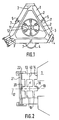
- cathodes and anodes constitute the electrodes of the laser gyro and are connected to the conduits 2 by connection conduits 7.
- the optical unit 1 is filled with a gaseous mixture generally based on helium and neon.
- a gaseous mixture generally based on helium and neon.
- An electric current passing between the electrodes excites this gas mixture and creates a plasma in the connection conduits 7 and in the conduits 2, plasma which, by amplifying the light, generates by laser effect, two light waves rotating in opposite directions in the cavity optical.
- This optical unit 1 is mounted oscillating around an axis thanks to an activation wheel.
- This consists of an outer ring 9, a central hub 10 and elastic blades 11 on which are bonded piezoelectric ceramics 12.
- metal parts 22 even if they are made of a material with a low coefficient of expansion, create, during temperature variations, stress variations in all of the parts which are a cause of instability, both for the length of the cavity, only for the angular position of the mirror.
- the piezoelectric bimetallic strip 21 is generally of the largest possible diameter, and its temperature expansions are then also a very significant cause of instability. These expansions can lead to creeping in the bimetallic strip itself and in the bonding of the fixing pieces 22. After creep, the tightening of the pieces can become insufficient, the bimetallic strip can move, all the stresses can change and all this is very detrimental to the performance of gyrolasers.
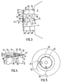
- FIG. 3 illustrates a first embodiment of a movable piezoelectric mirror according to the invention and the principle of which consists in making a piezoelectric motor whose piezoelectric dynamic is reduced, but whose thermal sensitivity is such that it compensates at least partially variations in the dimensions of the optical cavity in temperature.
- the assembly comprising the external part 13, the internal part 15 and the membranes 16, can be produced in the form of two substantially identical parts 68 and 69 each comprising half of each of said internal part 15 and external part 13 and a membrane 16, the two parts 68 and 69 being joined to the assembly by molecular adhesion 40 or by any other suitable method.
- the faces 20 and 23 of the internal 15 and external 13 parts are machined so as to be located in the same plane if the part 24 has been produced in the form of a flat disc.
- Said part 24 is glued, by its face 28, at its center on the end 20 of the internal part 15 and, at its periphery, on the end 23 of the external part 13, so that the ceramic 25, the most wide, or located outside the assembly.
- the internal diameter of the crown of the ceramic 26 is preferably chosen very slightly greater than that of the end 20 of the internal part 15.
- the internal diameter of the crown of the ceramic 24 can preferably be chosen smaller than that of the end 20 of the internal part 15, in order to increase the piezoelectric sensitivity of the system, and to give it the desired thermal sensitivity.
- the piezoelectric ceramics 24 and 25 are metallized on each of their faces, and a particular bonding is carried out to ensure, on the one hand, good transmission of mechanical stresses between said ceramics and the part 23 and, on the other hand, a good electrical connection to said metallized faces.
- FIG. 4 is a partial enlarged view of FIG. 3
- FIG. 6 is a partial enlarged view of the mobile piezoelectric mirror according to the invention, in external view along the axis 17.
- An adhesive film 29, having very good mechanical strength in the whole temperature range, is applied to almost the entire part 30 of the face 27 of the part 24 which receives the ceramic 25 to be fixed and which is covered by said ceramic.
- a point 31 of conductive adhesive is applied to the periphery of the aforementioned part 30 and projects outside of said part 30 so that said point of adhesive 31 is accessible once the ceramic 25 is bonded.
- two conductive wires 32 and 33 are fixed, one 32, by bonding with conductive glue, to the or one of the points of conductive glue 31, the other 33, by soldering to the metallization or possibly by bonding with conductive glue.
- the ceramic 24 is bonded in the same way and electrically connected by two conductive wires 37 and 38 which exit towards the outside of the piezoelectric movable mirror by a hole 70 produced in the external part 13 of said movable mirror.
- the piezoelectric mobile mirror of FIG. 3 operates as follows:
- the optical unit 1 Under the effect of an increase in temperature of the gyrolaser, the optical unit 1, whose coefficient of expansion is generally negative, contracts and the length of the optical cavity tends to decrease. At the same time, the two ceramics 25 and 26 tend to expand. The ceramic 25 placed outside, being wider, imposes on the part 24 a stress greater than that provided by the ceramic 26.
- piezoelectric ceramics Due to their small diameter and their small width, piezoelectric ceramics do not bring too great mechanical stresses to the part 24 and the latter does not risk breaking.
- the piezoelectric dynamics can be reduced since it no longer has to correct all of the thermal variations in the length of the optical cavity.
- the narrow width ceramics used therefore become quite sufficient to correct the residual variations in the dimensions of the optical cavity.
- FIG. 6 illustrates a second embodiment of the mobile piezoelectric mirror according to the invention, the constitution of which is very close to that described above and which differs therefrom in that the ceramic 25, used previously and wider than the ceramic 26, is replaced by a ceramic 39 substantially the same width as the ceramic 26, but thicker than the latter. In this case thermal compensation is obtained by the difference in thickness between the two ceramics 26 and 39.
- FIG. 7 illustrates, in axial section view, a third preferred embodiment of the invention which allows light to come out of the two light waves without losing any of the advantages of the embodiments already described.
- this third embodiment is similar to those described above, but the movable internal part, the fixed external part and the two membranes are produced in the form of two separate parts joined preferably by molecular adhesion.
- the stack of multi-electric layers 19 is such that the mirror which it constitutes lets part of the light pass through the two waves and thus leaves two light beams 64 and 65 outwards.
- Said part 24 is glued, by its face 28, in its center on the face 55 of the part 50 and, at its periphery, on the face 54 of said part 50, so that the ceramic 58, the widest, is located outside the set.
- the internal diameter of the crown of the ceramic 59 is preferably chosen very slightly greater than that of the face 55 of the part 49.
- the internal diameter of the ceramic crown 58 is chosen to be as small as possible while being wide enough to allow the two light beams 64 and 65 coming from the laser gyro to pass.
- the bonding and electrical bonding methods of the ceramics 58 and 59 can of course be the same as those described above with the aid of FIGS. 4 and 5.
- the membrane 52 Due to the widening of the internal part 51, the membrane 52 is stiffer than the membrane 48 or that the previous 16 membranes. It will therefore be necessary that the forces developed by the piezoelectric motor are greater, both for thermal compensation, than for the piezoelectric effect itself.
- the counterbore 57 makes it possible to increase the efficiency of the piezoelectric motor because the useful diameter of the part 28 is itself increased and because the diameter of the two ceramics 58 and 59 can then also be increased.
- the surface 54 although reduced, is largely sufficient for bonding, while the surface 53 is kept identical since it is preferably fixed to the surface 45 by molecular adhesion.
- the adhesive film not shown, existing between the part 28 and the face 55 of the part 49, is of course transparent to allow the two light waves to pass.
- the general dimensioning, as shown in FIG. 7, is such that the two light beams which have passed through the mirror can also pass through the internal part 43, the internal part 51, the part 28 and exit without touching the internal edges of the ceramic 58 .
- FIG. 9 illustrates, by way of example, a method of mixing the two light beams, preferably usable for summing the light intensities of said beams. Such a sum is generally used as a useful signal to achieve a control of the length of cavity.
- the mirror 62 and the photoelectric cell 63 can be fixed by numerous means to the mobile piezoelectric mirror or to the optical unit 1 directly. They can also be fixed directly on a plate or in a box inside which the gyrolaser would be fixed itself.
Landscapes
- Physics & Mathematics (AREA)
- Engineering & Computer Science (AREA)
- Optics & Photonics (AREA)
- Electromagnetism (AREA)
- Power Engineering (AREA)
- General Physics & Mathematics (AREA)
- Radar, Positioning & Navigation (AREA)
- Remote Sensing (AREA)
- Gyroscopes (AREA)
Claims (11)
dass besagte piezoelektrische Elemente kronenförmig ausgebildet sind und dass mindestens einer der beiden Durchmesser eines der besagten piezoelektrischen Elemente (25) im Verhältnis zum entsprechenden Durchmesser des anderen piezoelektrischen Elementes verschieden ist, um, unter dem Einfluss einer Temperaturänderung, eine Verformung der Scheibe zu bewirken, die eine Verschiebung des beweglichen Spiegels zur Folge hat, um Dimensionsänderungen des optischen Hohlraumes zu korrigieren.
dass das Zentrum der dünnen Scheibe (24) auf die achte Fläche (55) des zweiten Teils (49) geklebt ist und ihr Umfang auf die sechste Fläche (54) des besagten zweiten Teils (49), und dass die Innendurchmesser der Keramiken (58, 59) gross genug sind, um die aus dem Laserkreisel kommenden beiden Lichtstrahlenbündel (64 und 65) herauszulassen.
Applications Claiming Priority (2)
| Application Number | Priority Date | Filing Date | Title |
|---|---|---|---|
| FR8802750 | 1988-03-04 | ||
| FR8802750A FR2628201B1 (fr) | 1988-03-04 | 1988-03-04 | Miroir piezoelectrique pour gyrometre a laser |
Publications (2)
| Publication Number | Publication Date |
|---|---|
| EP0331581A1 EP0331581A1 (de) | 1989-09-06 |
| EP0331581B1 true EP0331581B1 (de) | 1991-11-13 |
Family
ID=9363907
Family Applications (1)
| Application Number | Title | Priority Date | Filing Date |
|---|---|---|---|
| EP19890400578 Expired - Lifetime EP0331581B1 (de) | 1988-03-04 | 1989-03-02 | Piezoelektrischer Spiegel für Laserkreisel |
Country Status (3)
| Country | Link |
|---|---|
| EP (1) | EP0331581B1 (de) |
| DE (1) | DE68900424D1 (de) |
| FR (1) | FR2628201B1 (de) |
Families Citing this family (6)
| Publication number | Priority date | Publication date | Assignee | Title |
|---|---|---|---|---|
| FR2645261B1 (fr) * | 1989-03-30 | 1991-07-26 | Salaberry Bernard De | Dispositif de melange et de lecture pour gyrometre a laser |
| US5116131A (en) * | 1990-04-19 | 1992-05-26 | Litton Systems, Inc. | Mirror transducer assembly for ring laser gyroscopes |
| US5162870A (en) * | 1991-04-09 | 1992-11-10 | Honeywell Inc. | Substrate for ring laser gyro with nonuniform outer rim |
| US5148076A (en) * | 1991-04-09 | 1992-09-15 | Honeywell Inc. | Apparatus for thermal tuning of path length control drivers |
| FR2763703A1 (fr) * | 1997-05-20 | 1998-11-27 | Sextant Avionique | Miroir a pastille reflechissante rapportee, utilisable dans un gyrometre laser |
| US5838440A (en) * | 1997-10-20 | 1998-11-17 | Honeywell Inc. | Path length controller piezo/wireboard bonding pattern |
Family Cites Families (4)
| Publication number | Priority date | Publication date | Assignee | Title |
|---|---|---|---|---|
| US4160184A (en) * | 1978-01-09 | 1979-07-03 | The Singer Company | Piezoelectric actuator for a ring laser |
| US4383763A (en) * | 1979-09-12 | 1983-05-17 | Litton Systems, Inc. | Controllable mirrors |
| GB2104283B (en) * | 1981-07-24 | 1986-02-05 | Litton Systems Inc | Piezoelectric transducer |
| EP0194301A1 (de) * | 1984-09-14 | 1986-09-17 | Honeywell Inc. | Stabilisierte weglängensteuerung |
-
1988
- 1988-03-04 FR FR8802750A patent/FR2628201B1/fr not_active Expired - Fee Related
-
1989
- 1989-03-02 EP EP19890400578 patent/EP0331581B1/de not_active Expired - Lifetime
- 1989-03-02 DE DE8989400578T patent/DE68900424D1/de not_active Expired - Fee Related
Also Published As
| Publication number | Publication date |
|---|---|
| EP0331581A1 (de) | 1989-09-06 |
| FR2628201A1 (fr) | 1989-09-08 |
| DE68900424D1 (de) | 1991-12-19 |
| FR2628201B1 (fr) | 1990-07-13 |
Similar Documents
| Publication | Publication Date | Title |
|---|---|---|
| EP2891876B1 (de) | Optischer Detektor eines Gases | |
| CH639762A5 (fr) | Transducteur de pression a element vibrant. | |
| EP0852726B1 (de) | Monolithischer beschleunigungsmessaufnehmer | |
| EP2414774B1 (de) | In zwei entkoppelten modi schwingendes element und verwendung in einem schwingkreisel | |
| EP0331581A1 (de) | Piezoelektrischer Spiegel für Laserkreisel | |
| FR2506008A1 (fr) | Transducteur capteur de vibrations pour gyroscopes a anneaux laser | |
| FR2510336A1 (fr) | Transducteur piezoelectrique | |
| EP0413713A1 (de) | Kompensierter, piezoelektrischer spiegel für laserkeisel | |
| EP0694824B1 (de) | Uhrwerk mit elektroakustischem Umsetzer | |
| EP0312552B1 (de) | Schaltung zur ausschaltung von parasitären drehungen eines beweglichen spiegels in laser-kreiselgeräten | |
| CA3211041A1 (fr) | Resonateur en vibration de flexion a haut facteur de qualite pour la realisation de references de temps, de capteurs de force ou de gyrometres | |
| EP0323359B1 (de) | Befestigungseinrichtung des Aktivierungsmechanismus für Laserkreisel | |
| EP0326776B1 (de) | Piezoelektrisch erregte mechanische Schwingeinrichtung und deren Anwendung bei einem Laserkreisel | |
| FR2645262A1 (fr) | Dispositif de mesure de position des faisceaux lumineux pour gyrometre a laser | |
| EP0425546A1 (de) | Redundante laserkreisel | |
| EP4127741B1 (de) | Detektor für elektrische felder | |
| FR2929774A1 (fr) | Dispositif de resonance micro-electromecanique a structure periodique. | |
| EP4685541A1 (de) | Teleskop | |
| FR2645261A1 (fr) | Dispositif de melange et de lecture pour gyrometre a laser | |
| FR2645263A1 (fr) | Capteur de position optique pour gyrometre a laser | |
| FR2763703A1 (fr) | Miroir a pastille reflechissante rapportee, utilisable dans un gyrometre laser | |
| WO2025133242A1 (fr) | Cellule de mesure pour la mesure de la force surfacique exercée par un flux de particules | |
| FR2775396A1 (fr) | Moteur piezoelectrique | |
| FR2742547A1 (fr) | Accelerometre vibrant monolithique et son procede de fabrication | |
| WO2004070450A1 (fr) | Dispositif d'orientation d'un objet |
Legal Events
| Date | Code | Title | Description |
|---|---|---|---|
| PUAI | Public reference made under article 153(3) epc to a published international application that has entered the european phase |
Free format text: ORIGINAL CODE: 0009012 |
|
| 17P | Request for examination filed |
Effective date: 19890313 |
|
| AK | Designated contracting states |
Kind code of ref document: A1 Designated state(s): BE CH DE GB IT LI LU NL |
|
| 17Q | First examination report despatched |
Effective date: 19900904 |
|
| RAP1 | Party data changed (applicant data changed or rights of an application transferred) |
Owner name: SEXTANT AVIONIQUE |
|
| GRAA | (expected) grant |
Free format text: ORIGINAL CODE: 0009210 |
|
| AK | Designated contracting states |
Kind code of ref document: B1 Designated state(s): BE CH DE GB IT LI LU NL |
|
| ITF | It: translation for a ep patent filed | ||
| GBT | Gb: translation of ep patent filed (gb section 77(6)(a)/1977) | ||
| REF | Corresponds to: |
Ref document number: 68900424 Country of ref document: DE Date of ref document: 19911219 |
|
| PLBE | No opposition filed within time limit |
Free format text: ORIGINAL CODE: 0009261 |
|
| STAA | Information on the status of an ep patent application or granted ep patent |
Free format text: STATUS: NO OPPOSITION FILED WITHIN TIME LIMIT |
|
| 26N | No opposition filed | ||
| EPTA | Lu: last paid annual fee | ||
| PGFP | Annual fee paid to national office [announced via postgrant information from national office to epo] |
Ref country code: LU Payment date: 20000302 Year of fee payment: 12 |
|
| PGFP | Annual fee paid to national office [announced via postgrant information from national office to epo] |
Ref country code: CH Payment date: 20000303 Year of fee payment: 12 |
|
| PGFP | Annual fee paid to national office [announced via postgrant information from national office to epo] |
Ref country code: BE Payment date: 20000313 Year of fee payment: 12 |
|
| PGFP | Annual fee paid to national office [announced via postgrant information from national office to epo] |
Ref country code: NL Payment date: 20000331 Year of fee payment: 12 |
|
| PG25 | Lapsed in a contracting state [announced via postgrant information from national office to epo] |
Ref country code: LU Free format text: LAPSE BECAUSE OF NON-PAYMENT OF DUE FEES Effective date: 20010302 |
|
| PGFP | Annual fee paid to national office [announced via postgrant information from national office to epo] |
Ref country code: GB Payment date: 20010302 Year of fee payment: 13 |
|
| PG25 | Lapsed in a contracting state [announced via postgrant information from national office to epo] |
Ref country code: LI Free format text: LAPSE BECAUSE OF NON-PAYMENT OF DUE FEES Effective date: 20010331 Ref country code: CH Free format text: LAPSE BECAUSE OF NON-PAYMENT OF DUE FEES Effective date: 20010331 Ref country code: BE Free format text: LAPSE BECAUSE OF NON-PAYMENT OF DUE FEES Effective date: 20010331 |
|
| PGFP | Annual fee paid to national office [announced via postgrant information from national office to epo] |
Ref country code: DE Payment date: 20010528 Year of fee payment: 13 |
|
| BERE | Be: lapsed |
Owner name: SEXTANT AVIONIQUE Effective date: 20010331 |
|
| PG25 | Lapsed in a contracting state [announced via postgrant information from national office to epo] |
Ref country code: NL Free format text: LAPSE BECAUSE OF NON-PAYMENT OF DUE FEES Effective date: 20011001 |
|
| REG | Reference to a national code |
Ref country code: CH Ref legal event code: PL |
|
| NLV4 | Nl: lapsed or anulled due to non-payment of the annual fee |
Effective date: 20011001 |
|
| REG | Reference to a national code |
Ref country code: GB Ref legal event code: IF02 |
|
| PG25 | Lapsed in a contracting state [announced via postgrant information from national office to epo] |
Ref country code: GB Free format text: LAPSE BECAUSE OF NON-PAYMENT OF DUE FEES Effective date: 20020302 |
|
| PG25 | Lapsed in a contracting state [announced via postgrant information from national office to epo] |
Ref country code: DE Free format text: LAPSE BECAUSE OF NON-PAYMENT OF DUE FEES Effective date: 20021001 |
|
| GBPC | Gb: european patent ceased through non-payment of renewal fee |
Effective date: 20020302 |
|
| PG25 | Lapsed in a contracting state [announced via postgrant information from national office to epo] |
Ref country code: IT Free format text: LAPSE BECAUSE OF NON-PAYMENT OF DUE FEES Effective date: 20050302 |