EP0331690B1 - Revetement pour plafonds - Google Patents
Revetement pour plafonds Download PDFInfo
- Publication number
- EP0331690B1 EP0331690B1 EP88907303A EP88907303A EP0331690B1 EP 0331690 B1 EP0331690 B1 EP 0331690B1 EP 88907303 A EP88907303 A EP 88907303A EP 88907303 A EP88907303 A EP 88907303A EP 0331690 B1 EP0331690 B1 EP 0331690B1
- Authority
- EP
- European Patent Office
- Prior art keywords
- struts
- ceiling facing
- longitudinal
- extending
- cassette
- Prior art date
- Legal status (The legal status is an assumption and is not a legal conclusion. Google has not performed a legal analysis and makes no representation as to the accuracy of the status listed.)
- Expired - Lifetime
Links
- 238000007789 sealing Methods 0.000 claims description 25
- 230000007704 transition Effects 0.000 claims description 4
- 239000013013 elastic material Substances 0.000 claims description 2
- 229910052751 metal Inorganic materials 0.000 claims description 2
- 239000002184 metal Substances 0.000 claims description 2
- 239000007787 solid Substances 0.000 claims description 2
- 238000009434 installation Methods 0.000 description 10
- 238000005253 cladding Methods 0.000 description 9
- 230000000694 effects Effects 0.000 description 4
- 230000000007 visual effect Effects 0.000 description 4
- 229910052782 aluminium Inorganic materials 0.000 description 2
- XAGFODPZIPBFFR-UHFFFAOYSA-N aluminium Chemical compound [Al] XAGFODPZIPBFFR-UHFFFAOYSA-N 0.000 description 2
- 230000008901 benefit Effects 0.000 description 2
- 230000003287 optical effect Effects 0.000 description 2
- 238000003860 storage Methods 0.000 description 2
- 244000089486 Phragmites australis subsp australis Species 0.000 description 1
- 229910000831 Steel Inorganic materials 0.000 description 1
- 239000000853 adhesive Substances 0.000 description 1
- 230000001070 adhesive effect Effects 0.000 description 1
- 230000015572 biosynthetic process Effects 0.000 description 1
- 238000010276 construction Methods 0.000 description 1
- 230000002349 favourable effect Effects 0.000 description 1
- 239000006260 foam Substances 0.000 description 1
- 230000001771 impaired effect Effects 0.000 description 1
- 230000003993 interaction Effects 0.000 description 1
- 230000001788 irregular Effects 0.000 description 1
- 238000004519 manufacturing process Methods 0.000 description 1
- 238000012986 modification Methods 0.000 description 1
- 230000004048 modification Effects 0.000 description 1
- 239000003973 paint Substances 0.000 description 1
- 239000002245 particle Substances 0.000 description 1
- 238000003825 pressing Methods 0.000 description 1
- 230000000284 resting effect Effects 0.000 description 1
- 239000003566 sealing material Substances 0.000 description 1
- 239000010959 steel Substances 0.000 description 1
- 230000008719 thickening Effects 0.000 description 1
Images




Classifications
-
- E—FIXED CONSTRUCTIONS
- E04—BUILDING
- E04B—GENERAL BUILDING CONSTRUCTIONS; WALLS, e.g. PARTITIONS; ROOFS; FLOORS; CEILINGS; INSULATION OR OTHER PROTECTION OF BUILDINGS
- E04B9/00—Ceilings; Construction of ceilings, e.g. false ceilings; Ceiling construction with regard to insulation
- E04B9/06—Ceilings; Construction of ceilings, e.g. false ceilings; Ceiling construction with regard to insulation characterised by constructional features of the supporting construction, e.g. cross section or material of framework members
-
- E—FIXED CONSTRUCTIONS
- E04—BUILDING
- E04B—GENERAL BUILDING CONSTRUCTIONS; WALLS, e.g. PARTITIONS; ROOFS; FLOORS; CEILINGS; INSULATION OR OTHER PROTECTION OF BUILDINGS
- E04B9/00—Ceilings; Construction of ceilings, e.g. false ceilings; Ceiling construction with regard to insulation
- E04B9/06—Ceilings; Construction of ceilings, e.g. false ceilings; Ceiling construction with regard to insulation characterised by constructional features of the supporting construction, e.g. cross section or material of framework members
- E04B9/064—Ceilings; Construction of ceilings, e.g. false ceilings; Ceiling construction with regard to insulation characterised by constructional features of the supporting construction, e.g. cross section or material of framework members comprising extruded supporting beams
-
- E—FIXED CONSTRUCTIONS
- E04—BUILDING
- E04B—GENERAL BUILDING CONSTRUCTIONS; WALLS, e.g. PARTITIONS; ROOFS; FLOORS; CEILINGS; INSULATION OR OTHER PROTECTION OF BUILDINGS
- E04B9/00—Ceilings; Construction of ceilings, e.g. false ceilings; Ceiling construction with regard to insulation
- E04B9/06—Ceilings; Construction of ceilings, e.g. false ceilings; Ceiling construction with regard to insulation characterised by constructional features of the supporting construction, e.g. cross section or material of framework members
- E04B9/12—Connections between non-parallel members of the supporting construction
-
- E—FIXED CONSTRUCTIONS
- E04—BUILDING
- E04B—GENERAL BUILDING CONSTRUCTIONS; WALLS, e.g. PARTITIONS; ROOFS; FLOORS; CEILINGS; INSULATION OR OTHER PROTECTION OF BUILDINGS
- E04B9/00—Ceilings; Construction of ceilings, e.g. false ceilings; Ceiling construction with regard to insulation
- E04B9/18—Means for suspending the supporting construction
- E04B9/183—Means for suspending the supporting construction having a lower side adapted to be connected to a channel of the supporting construction
-
- E—FIXED CONSTRUCTIONS
- E04—BUILDING
- E04B—GENERAL BUILDING CONSTRUCTIONS; WALLS, e.g. PARTITIONS; ROOFS; FLOORS; CEILINGS; INSULATION OR OTHER PROTECTION OF BUILDINGS
- E04B9/00—Ceilings; Construction of ceilings, e.g. false ceilings; Ceiling construction with regard to insulation
- E04B9/22—Connection of slabs, panels, sheets or the like to the supporting construction
-
- E—FIXED CONSTRUCTIONS
- E04—BUILDING
- E04B—GENERAL BUILDING CONSTRUCTIONS; WALLS, e.g. PARTITIONS; ROOFS; FLOORS; CEILINGS; INSULATION OR OTHER PROTECTION OF BUILDINGS
- E04B9/00—Ceilings; Construction of ceilings, e.g. false ceilings; Ceiling construction with regard to insulation
- E04B9/22—Connection of slabs, panels, sheets or the like to the supporting construction
- E04B9/24—Connection of slabs, panels, sheets or the like to the supporting construction with the slabs, panels, sheets or the like positioned on the upperside of, or held against the underside of the horizontal flanges of the supporting construction or accessory means connected thereto
- E04B9/241—Connection of slabs, panels, sheets or the like to the supporting construction with the slabs, panels, sheets or the like positioned on the upperside of, or held against the underside of the horizontal flanges of the supporting construction or accessory means connected thereto with the slabs, panels, sheets or the like positioned on the upperside of the horizontal flanges of the supporting construction
- E04B9/242—Connection of slabs, panels, sheets or the like to the supporting construction with the slabs, panels, sheets or the like positioned on the upperside of, or held against the underside of the horizontal flanges of the supporting construction or accessory means connected thereto with the slabs, panels, sheets or the like positioned on the upperside of the horizontal flanges of the supporting construction with separate retaining elements
-
- E—FIXED CONSTRUCTIONS
- E04—BUILDING
- E04B—GENERAL BUILDING CONSTRUCTIONS; WALLS, e.g. PARTITIONS; ROOFS; FLOORS; CEILINGS; INSULATION OR OTHER PROTECTION OF BUILDINGS
- E04B9/00—Ceilings; Construction of ceilings, e.g. false ceilings; Ceiling construction with regard to insulation
- E04B9/30—Ceilings; Construction of ceilings, e.g. false ceilings; Ceiling construction with regard to insulation characterised by edge details of the ceiling; e.g. securing to an adjacent wall
-
- E—FIXED CONSTRUCTIONS
- E04—BUILDING
- E04F—FINISHING WORK ON BUILDINGS, e.g. STAIRS, FLOORS
- E04F13/00—Coverings or linings, e.g. for walls or ceilings
- E04F13/07—Coverings or linings, e.g. for walls or ceilings composed of covering or lining elements; Sub-structures therefor; Fastening means therefor
- E04F13/08—Coverings or linings, e.g. for walls or ceilings composed of covering or lining elements; Sub-structures therefor; Fastening means therefor composed of a plurality of similar covering or lining elements
- E04F13/12—Coverings or linings, e.g. for walls or ceilings composed of covering or lining elements; Sub-structures therefor; Fastening means therefor composed of a plurality of similar covering or lining elements of metal or with an outer layer of metal or enameled metal
Definitions
- the invention relates to a gas and dust-tight ceiling cladding made of metal, consisting of a rigid support grid and cassettes arranged in the grid fields of the support grid, wherein the support grid is made up of continuous longitudinal struts and transverse struts connected to them, and each longitudinal strut and each cross strut in each Longitudinally extending and arranged on both sides at their lower end, substantially horizontally extending projections, on the top of which are arranged seals on which the cassettes lie sealingly.
- an intermediate ceiling which has longitudinal and transverse struts which are suspended from node pieces. Since the struts are held at the junctions only by their own weight, these elements are not fixed. In addition, the longitudinal and transverse struts are only roll-formed profiles that are not torsionally rigid, so that the false ceiling can be twisted and the necessary gas tightness can no longer be guaranteed. Like the longitudinal and cross struts, the cassettes are only held by their own weight. This can have a particularly disadvantageous effect if excess pressure is used in the rooms suspended with this false ceiling, since the cassettes can be raised due to the lack of fixation. The same applies, for example, to sterile ceilings in laboratories if a vacuum is created in the ceiling cavity to extract dirt particles.
- GB-A-2087451 describes a suspended ceiling in which cross members are fastened to the longitudinal members via a snap-in connection.
- a locking lug is provided on the cross member and a corresponding recess is provided on the longitudinal member.
- a very precise design of the catch and recess is required, as well as correspondingly precise and therefore complex assembly. If the locking lug is pressed too deep into the recess, the cross member is higher than the longitudinal member, so that there is no precisely defined position of the carrier in this blanket. In addition, the flush mounting of cassettes and support system is not guaranteed with this false ceiling.
- the invention has for its object to provide a ceiling cladding of the type mentioned, which allows a stable, optically appealing and gas-tight cladding even with variable grid dimensions with simple construction and easy assembly and disassembly of the cassettes.
- the object is achieved in that the lateral projections of the longitudinal struts and the cross struts or the longitudinal struts and cross struts themselves are each formed from box-shaped, torsionally rigid profiles.
- the projections on the top have at least one upwardly extending web which runs along the respective projection.
- the seals are between the web and the side wall of the struts or can also be accommodated between them in the case of a plurality of webs.
- the cassettes of spring elements are pressed onto the webs, the spring elements being supported on the side walls of the struts.
- the depth and contour of the cassettes are designed such that their closed bottom surfaces are arranged flush with the struts.
- the ceiling covering according to the invention is characterized by a number of considerable advantages.
- Another important advantage of the invention is that the weight of the cassettes does not rest directly on the seals, as is known from the prior art, but is carried by the webs, while the seals are only in contact with corresponding surfaces of the cassettes to create a gastight seal to guarantee. Damage to the seals is thus avoided.
- the cassettes since the cassettes always rest completely on the respective webs, it is also ensured that the seals on the entire circumference of the cassettes are in engagement, so that a gas-tight seal is ensured. Furthermore, the seal is protected against damage even when the cassette is removed and is not visible, in particular when the cassette is inserted, so that the overall visual impression is not impaired. Finally, the cassettes are always held in their inserted position by the spring elements fixing them.
- the seal can also have a rectangular cross section and be designed as a solid profile, it proving to be advantageous if the sealing material as a whole has sufficient elasticity.
- the seal In order to connect the seal to the projection in a secure manner, it preferably has a flat contact surface which can be glued to the projection, for example.
- This flat contact surface can be provided both in the case of a tubular seal and in the case of a rectangular seal.
- the seal is preferably made of an elastic material with a closed surface manufactured, for example from a closed-cell foam or the like.
- a further web can be arranged parallel to the web between the web and the wall of the longitudinal strut or the cross strut. This further web is used to form a U-shaped channel cross section, in which the seal is inserted.
- This design measure prevents spring elements which are arranged on the longitudinal web and on the cross web from being able to damage the seal.
- the cassette can prove to be advantageous for the cassette to have a circumferential step fold on its outer lower edge region, the cassette resting with the horizontal surface of the step fold on the projections or the webs.
- the formation of the step fold makes it possible to arrange the lower surface of the cassette flush with the lower surfaces of the longitudinal struts and transverse struts.
- the spring elements fixing the cassettes in their position on the longitudinal struts and / or on the cross struts are designed as leaf springs, the ends of these leaf springs being held in opposing grooves formed on the side walls of the longitudinal or cross struts.
- the spring elements thus bring about a firm support of the cassettes on the webs of the projections, so that the cassettes lie exactly on the optical point of view and are pressed into contact with the seals with regard to the required sealing effect.
- the springs have an angled section between the two ends, one leg of which extends essentially vertically, is resiliently supported on the side surface of the cassette and up to approximately runs at the level of the upper edge of the cassette, and its other leg runs above the upper edge of the cassette and is angled outwardly with respect to the side wall of the strut. It can furthermore prove to be advantageous if one leg is adjoined by a leg which preferably extends in a straight line towards the lower groove and on the other leg a leg which preferably extends in a straight line to the upper groove. Furthermore, a spring end section, which runs parallel to the side wall of the strut, can connect to the legs of the tongue that extend toward the grooves. All of these configurations improve the pressing of the cassettes against the webs and ensure an adequate seal.
- the invention provides that the grid fields at the transition area to a wall are delimited by a wall connecting strut. This configuration gives the possibility of even irregular wall shapes in a sealing connection to the Bring ceiling paneling. It may also be favorable that the wall connection strip has a horizontal projection extending in its longitudinal direction, on the upper side of which a seal which can be brought into contact with the cassette is arranged. This configuration ensures that a gas-tight seal is also present in the transition area to the wall.
- a second projection parallel to this is arranged above the first projection, below which a horizontal region of the cassette can be inserted. The cassette is thus guided and held in a U-shaped groove, thus moving the cassette or unintentionally loosening is excluded.
- the seal has a U-shaped cross section and is mounted on the second projection and comprises at least one sealing lip pointing in the direction of the first projection.
- the sealing lip is in contact with the horizontal area of the cassette and enables a gas-tight seal. Since the sealing lip extends into the U-shaped area between the first and the second projection, a sufficient pretensioning force of the seal is ensured at the same time.
- the cassette is provided with internally mounted internals which can be designed, for example, in the form of a lamp or an air supply / air discharge device. This proves to be advantageous because no additional leakage points are possible due to additional internals or attachments.
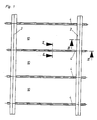
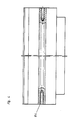
- the ceiling covering according to the invention consists essentially of horizontally arranged, mutually parallel longitudinal struts 2, of cross struts 4, which are arranged between the longitudinal struts 2 and are each fastened with their ends to the longitudinal struts, and of cassettes 6, of the longitudinal struts 2 and the cross struts 4 are worn.
- the longitudinal struts 2 are above one another from the upper side 12 of the longitudinal struts 2 supporting straps 14 extending at the top are fastened to supports 8, which in turn are height-adjustable, for example by means of threaded rods 16, relative to the ceiling, not shown.
- the support straps 14 of the longitudinal struts 2 are angled at their upper end, so that the longitudinal struts can be suspended from the supports 8 via the horizontally extending angle leg 18 of the support strap 14.
- the support straps 14 are secured to the supports 8 by means of screws 20.
- the longitudinal struts 2 and the cross struts 4 are designed as aluminum profiles.
- the cassettes 6 carried by the longitudinal struts 2 and the cross struts 4 are made of electrolytically galvanized sheet steel, the visible sides of both the cassettes 6 and the longitudinal struts 2 and the cross struts 4 being coated with thermally hardened paint, for example in the color RAL 9010.
- the shape of the longitudinal struts 2 can be seen in particular from FIG. 3.
- the longitudinal struts 2 are designed essentially as a rectangular box section, the upper side 12 of the box section being largely open so that the inside of the box section is accessible.
- Continuous, laterally projecting supports 26 are formed on the two longitudinal sides 22, 24 of the box section in the longitudinal direction of the longitudinal struts. These supports 26 are also designed in the manner of a box profile, the underside 28 of the supports 26 being in one plane with the underside 30 of the longitudinal strut 2 in the manner of a box profile.
- Three vertical webs 34, 36, 38, which extend in the longitudinal direction of the longitudinal strut 2, are each formed on the upward-facing upper side 32 of each support 26, the outer web 34 extending the side wall 40 of the box-shaped support 26 represents, the web 38 is arranged near the longitudinal side 22 of the longitudinal strut 2 and with this defines a groove 42 and the web 36 is arranged between the web 34 and the web 38.
- a sealing strip 44 is inserted, which can be made of rubber, for example, extends over the entire length of the longitudinal strut and, in the non-compressed state, projects slightly beyond the upper edges of the webs 34, 36.
- a web 46 is formed, which runs parallel to the long sides and over the entire length of the long sides and defines a groove 48 between them and the adjacent side wall 22 or 24.
- the opposing grooves 42, 48 serve to receive springs 50 to be described in more detail below.
- galvanized grate angles with additional diagonal struts are provided as thrust beams at a distance of, for example, 100 cm.
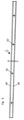
- the structure of the cross struts 4 can be seen in particular from FIG. 2.
- the cross struts 4 are also designed as an aluminum profile and comprise an upright ledge 80, along the lower end of which on both sides in the longitudinal direction of the bar 80 extending supports 56 are formed, which extend to both sides of the line 80 and whose undersides 58 form the underside of the cross struts.
- the supports 56 have the same cross-section as the supports 26 of the longitudinal struts 2 and are therefore designed in the manner of a box profile with side walls 70 and upper sides 62, from which webs 64, 66, 68 extending in the longitudinal direction extend upwards, between the webs 64, 66 Sealing strips 74 are arranged, and wherein grooves 72 are formed between the webs 68 and the adjacent side surface of the strip 80.
- longitudinally extending, downwardly pointing webs 76 are formed which define grooves 78 between themselves and the adjacent side faces of the strip 80.
- the opposing grooves 72, 78 serve, as in the case of the longitudinal struts 2, for receiving the ends of springs 50.
- a stiffening bar 60 running at right angles to the level of the bar 80 is formed along the upper edge of the cross bars 4.
- the strip 80 has a thickening 82 extending approximately in the center in the longitudinal direction, in which a threaded bore 84 extending in the longitudinal direction of the cross strut 4 is formed in the center.
- the cross struts 4 are provided at their lower end edges with a step-shaped, rectangular recess 86 which is dimensioned such that the cross struts 4 when attached to the longitudinal struts 2 with the upper, horizontal surface of the recess 86 on the Support 26 and at the same time rest with their end face 87 on the outer sides of the webs 46 of the longitudinal struts 2.
- the width of the cross struts 4 can be approximately 4 cm and the height of the cross struts 4 corresponds the height of the longitudinal struts 2 and is thus 7.2 cm.
- the screws 54 are guided from the inside of the longitudinal struts 2 through the through bores 52 of the longitudinal sides 22, 24 of the longitudinal struts 2 and screwed into the threaded bores 84 of the cross struts 4 opposite the through bores 52.
- the dimensions of the cassettes 6 are somewhat smaller than the grid dimensions defined by the long sides 22, 24 of the longitudinal struts and the outer sides of the strip 80 of the cross struts, but larger than the grid dimensions defined by the side walls 40, 70 of the supports 26, 56.
- the cassettes 6 are provided with a circumferential step fold 88 at the bottom.
- the cassettes 6 When the cassettes 6 are inserted into the grid fields 10 defined by the longitudinal struts 2 and the cross struts 4, they lie with the horizontal surfaces 90 of the step fold 88 in a sealing manner on the sealing strips 44, 74 carried by the supports 26, 56.
- the height of the step fold 88 is designed so that the undersides 92 are flush with the undersides of the longitudinal struts 2 and the cross struts 4.
- the springs 50 carried on the longitudinal struts 2 and the cross struts 4 are provided to fix the position of the cassettes 6.
- the springs 50 each have a leg running parallel to the longitudinal sides 22, 24 or the strip 80 at their two ends, the lower leg of the spring 50 in the groove 42 or 72 and the upper leg of the spring 50 in the upper Groove 48 and 78 is guided.
- a vertical leg 94 is formed on the springs 50, which bears against the side wall of the cassette 6 in the region of its upper edge, up to the region of the upper edge 96 of the cassette extends and rests under tension on the cassette.
- This vertical leg of the spring 50 is adjoined by a short leg 98, which extends obliquely upward on the outside.
- a straight leg 100 leads to the upper end region of the tongue 50, which is guided in the groove 48 or 78.
- a straight leg 102 of the tongue 50 leads to the lower, in of the groove 42 and 72 guided end portion of the spring 50th
- the springs 50 are distributed on the longitudinal struts 2 and the cross struts 4 for each cassette 6.
- the springs 50 can be inserted into the guide grooves in a simple manner by compressing the legs 100, 102 at the desired location.
- the springs 50 can also be moved within the guide grooves if necessary.
- the lower edges of the cassettes 6 run onto the legs 100 of the springs 50 and push them to the side.
- the springs snap with their legs 98, 100 to the outside over the upper edge of the cassettes 6 while at the same time the vertical legs 94 rest against the side surfaces of the cassette 6. In this way, the Cassettes 6 held securely in their target position.
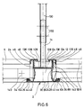
- FIG. 6 shows a sectional view, similar to FIG. 3, through a longitudinal strut of the support grid according to the invention, which essentially corresponds in structure to the longitudinal strut shown in FIG. 3.
- the same parts have been given the same reference numbers.
- the longitudinal strut shown in Fig. 6 has on the projections 26 each upwardly extending webs 34 on which, as shown, the cassettes 6 with a horizontal surface of the Step fold 88 rest. It is thus ensured that the cassettes are always in contact with the webs 34, so that an exact assignment and alignment of the arrangement of the undersides 30 of the longitudinal struts and the undersides of the cassettes 6 is ensured.
- a seal 44 is arranged which has a flat lower contact surface 104 which can be connected to a horizontal region of the projection 26, for example by means of an adhesive connection.
- the seal 44 is essentially tubular and in the unloaded state has a height which is greater than the corresponding height of the web 34. In this way it is ensured that the seal 44 is always compressed to a predetermined extent when the cassettes 6 are placed on it .
- the longitudinal strut shown in FIG. 6 is designed in the form of a hollow profile and has an essentially rectangular, closed conduit channel 124, which is formed by the underside 30, the longitudinal sides 24 and a horizontally running separating web 126.
- the conduit 124 is thus self-contained and sealed against a tubular cross-sectional area 128 arranged above it.
- the tubular cross-sectional area essentially has a U-shaped configuration, so that the mounting bracket 14 can be inserted into it, as shown in FIG. 6.
- the conduit 124 can be used to pass electrical cables or pipes, for example for a sprinkler system. Due to its sealing by means of the separating web 126, it is also possible to add attachments to the underside 30 of the longitudinal strut 2, for example dividing walls, additional lights or the like, without this affecting the tightness of the ceiling cladding would.
- the carrying strap 14 is connected to a hanger 130, it being possible for the connection to be made by means of bolts or screws 132 which are only indicated schematically.
- upper and lower grooves 48, 42 are formed, which are used to hold a spring 50 or a spring element.
- An embodiment of such a spring element 50 is shown on the right half of FIG. 6.
- the support bracket 14 In order to ensure secure attachment to the support bracket 14, it has a lower transverse region, from the outer upper edge view of which retaining tabs 136 extend upwards, which can be introduced into U-shaped grooves which are formed by edges 138 of the top sides 12. Thus, loosening of the support bracket 14 is reliably prevented even when vibrations occur.
- a connection between the longitudinal strut 2 and a cross strut 4 can take place by means of an angle 140, which is formed in a longitudinal groove 142 of the longitudinal side 24 of the longitudinal strut 2.
- the angle 140 can be screwed to the longitudinal strut 2, for example.
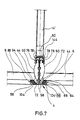
- FIG. 7 shows an embodiment, similar to FIG. 2, of a cross strut according to the invention, which corresponds in terms of its lateral structure to the longitudinal strut shown in FIG. 6.
- the webs 64 are designed such that the cassettes with their step fold 88 rest directly on the webs 64, but not on the seals 44.
- the seal 44 is the same Formed as in the embodiment shown in Fig. 6.
- the upper and lower grooves 78, 72 for receiving the spring elements 50 are formed in the same way.
- the cross strut shown in Fig. 7 can be suspended by means of a support bracket 14 ', which has at its lower end a holding element 144 which has a substantially U-shaped cross section, by means of which a gripping of the upper region of the cross strut is possible.
- the free ends of the holding element 144 are bent inwards in order to engage behind the webs 76. Since both the spring 50 and the support straps 14 'each extend only over a limited length of the cross strut, no undesirable interaction occurs between them.
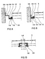
- FIGS. 8 and 9 show exemplary embodiments of a wall end strut according to the invention, by means of which a wall connection of a cassette 6 can be designed to suit the local conditions.
- the cassette 6 is provided with a horizontal region 116, which can be designed, for example, in the form of part of the underside of the cassette 6.
- the wall connection strut 106 has a first horizontal projection 110, on which the horizontal region 116 of the cassette 6 can be placed. This configuration ensures secure storage of the cassette 6. Essentially parallel to the first projection 110, a second projection 114 is formed in one piece with the wall connection strut 106, at the free end of which a seal 112 is arranged, which engages around the second projection 114 and has at least one sealing lip 118 on its underside, which seals against the first Bias 110 biased is. When the horizontal region 116 is inserted, a seal is thus made in a reliable manner.
- the wall connection strut 106 can be designed in the form of an angle profile which can be screwed to a wall 108. However, it is also possible to design the wall connection strut 106 in the form of a double-angle profile, as shown in FIG. 8, in order to form a shadow groove 146 in this way.
- FIG. 10 shows an exemplary embodiment of an installation for a cassette 6.
- the installation is in the form of a pipe 148, only shown schematically, which can be used, for example, for a sprinkler system.
- an annular seal 149 is inserted, which comprises an annular sealing lip 150 which is in contact with the outer surface of the tube 148 and thus represents a reliable seal.
- the tube 148 can either be attached to the cassette 6 or to a ceiling arranged above it.
- FIG. 11 shows a further exemplary embodiment of an installation of a cassette 6, which is designed in the form of a lamp 120 which is only shown schematically.
- the lamp 120 is firmly connected to the cassette 6 and has a housing which is closed toward the top. A gas-tight seal between the lamp 120 and the cassette 6 takes place via a seal 152.
- the lamp 120 is installed or removed together with the cassette 6.
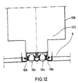
- FIG. 12 shows a further exemplary embodiment of an installation of a cassette, the installation being designed in the form of an air supply or air discharge device 122.
- a box 158 of the air installation 122 is via seals 156, which are tightly connected to the cassette 6, for Sealed top of the cassette, the seals 156 also serve to hold air nozzles 154. With this embodiment it is also possible to firmly connect the air installation 122 to the cassette.
- FIG. 13 shows a perspective bottom view of a ceiling covering according to the invention, cassettes 6 being inserted between the longitudinal struts 2 and the cross struts 4, some of which are provided with light fixtures 120 or air fixtures 122.
Landscapes
- Engineering & Computer Science (AREA)
- Architecture (AREA)
- Civil Engineering (AREA)
- Structural Engineering (AREA)
- Physics & Mathematics (AREA)
- Electromagnetism (AREA)
- Supports For Pipes And Cables (AREA)
- Road Signs Or Road Markings (AREA)
- Rod-Shaped Construction Members (AREA)
- Connection Of Plates (AREA)
- Buffer Packaging (AREA)
- Vehicle Interior And Exterior Ornaments, Soundproofing, And Insulation (AREA)
- Filtering Of Dispersed Particles In Gases (AREA)
- Securing Globes, Refractors, Reflectors Or The Like (AREA)
- Arrangement Of Elements, Cooling, Sealing, Or The Like Of Lighting Devices (AREA)
Abstract
Claims (18)
Priority Applications (1)
| Application Number | Priority Date | Filing Date | Title |
|---|---|---|---|
| AT88907303T ATE69632T1 (de) | 1987-08-18 | 1988-08-17 | Deckenverkleidung. |
Applications Claiming Priority (2)
| Application Number | Priority Date | Filing Date | Title |
|---|---|---|---|
| DE8711244U DE8711244U1 (de) | 1987-08-18 | 1987-08-18 | Deckenverkleidung |
| DE8711244U | 1987-08-18 |
Publications (2)
| Publication Number | Publication Date |
|---|---|
| EP0331690A1 EP0331690A1 (fr) | 1989-09-13 |
| EP0331690B1 true EP0331690B1 (fr) | 1991-11-21 |
Family
ID=6811195
Family Applications (2)
| Application Number | Title | Priority Date | Filing Date |
|---|---|---|---|
| EP88907303A Expired - Lifetime EP0331690B1 (fr) | 1987-08-18 | 1988-08-17 | Revetement pour plafonds |
| EP88907274A Expired - Lifetime EP0332672B1 (fr) | 1987-08-18 | 1988-08-17 | Revetement de plafond |
Family Applications After (1)
| Application Number | Title | Priority Date | Filing Date |
|---|---|---|---|
| EP88907274A Expired - Lifetime EP0332672B1 (fr) | 1987-08-18 | 1988-08-17 | Revetement de plafond |
Country Status (6)
| Country | Link |
|---|---|
| US (2) | US5410853A (fr) |
| EP (2) | EP0331690B1 (fr) |
| JP (2) | JPH02500608A (fr) |
| KR (2) | KR890701854A (fr) |
| DE (3) | DE8711244U1 (fr) |
| WO (2) | WO1989001551A1 (fr) |
Families Citing this family (24)
| Publication number | Priority date | Publication date | Assignee | Title |
|---|---|---|---|---|
| DE3802309A1 (de) * | 1988-01-27 | 1989-08-10 | Albrecht Ritter | Unterdecke mit einem abgehaengten traggerippe |
| USD338536S (en) | 1991-04-26 | 1993-08-17 | Gifford Sr John E | Ceiling grip cover strip |
| US5287668A (en) * | 1992-07-15 | 1994-02-22 | Capaul Corporation | Apparatus and method for refurbishing a ceiling grid to permit installation of ceiling panels |
| US5737888A (en) * | 1996-01-19 | 1998-04-14 | Heat-N-Glo Fireplace Products Inc. | Versatile surround trim structure |
| FR2745316B1 (fr) * | 1996-02-22 | 1998-04-24 | Clestra Cleanroom Sa | Plafond suspendu pour salles blanches |
| DE19803080A1 (de) * | 1998-01-28 | 1999-07-29 | Meissner & Wurst | Deckenraster für Reinräume |
| US6351920B1 (en) * | 1999-04-22 | 2002-03-05 | Clean Pak International, Inc. | Ceiling module perimeter seal |
| US7260919B1 (en) * | 2002-04-16 | 2007-08-28 | Daw Technologies, Inc. | Sealable ceiling assembly |
| DE60310652T2 (de) * | 2002-07-30 | 2007-10-04 | Hunter Douglas Industries B.V. | Paneelaufbau für abgehängte Decken |
| US6701686B1 (en) * | 2003-01-16 | 2004-03-09 | Worthington Armstrong Venture | Ceiling grid with seal |
| US6779315B1 (en) * | 2003-05-15 | 2004-08-24 | Vincent J. Bongio | Suspended ceiling/raised floor connection system |
| US8051612B2 (en) * | 2007-01-10 | 2011-11-08 | Woodard Kramer E | Wall system having biasing members retaining panels to posts that are secured by anchoring structure |
| US20090000231A1 (en) * | 2007-06-28 | 2009-01-01 | Burns Steven A | Sealing System for Suspended Ceilings |
| US7886496B1 (en) * | 2007-08-20 | 2011-02-15 | Daw Technologies, Inc. | Extruded aluminum bottom-load ceiling |
| US20090188175A1 (en) * | 2008-01-25 | 2009-07-30 | Waters James R | Cantilevered ceiling system |
| US20130042560A1 (en) * | 2011-08-16 | 2013-02-21 | Worthington Armstrong Venture | Noise damper |
| KR101424764B1 (ko) * | 2013-06-14 | 2014-08-01 | 주식회사 조은데코 | 천장 마감장치 |
| US9435121B2 (en) * | 2014-11-26 | 2016-09-06 | Awi Licensing Llc | Assembly for supporting ceiling panels and ceiling system incorporating the same |
| ITUA20163089A1 (it) * | 2016-05-03 | 2017-11-03 | Oc S R L | Sistema di montaggio di controsoffitto. |
| US9771718B1 (en) | 2016-10-07 | 2017-09-26 | Tate Access Floors Leasing, Inc. | Strut with non-structural infill |
| US11821205B2 (en) | 2020-08-31 | 2023-11-21 | Porta-Fab Corporation | Modular ceiling system |
| US11459753B2 (en) * | 2020-08-31 | 2022-10-04 | Porta-Fab Corporation | Modular ceiling system |
| US12209407B1 (en) * | 2021-01-20 | 2025-01-28 | Gordon Sales, Inc. | Narrow gap filling structure |
| US12024881B1 (en) | 2021-01-20 | 2024-07-02 | Gordon Sales, Inc. | Telescoping wall gap filler assembly |
Family Cites Families (20)
| Publication number | Priority date | Publication date | Assignee | Title |
|---|---|---|---|---|
| CH295593A (de) * | 1953-05-11 | 1954-01-15 | Ernst Koller | Sprosse zum Befestigen von Glastafeln, insbesondere für Glaswände mit Skelettkonstruktion. |
| US2882561A (en) * | 1955-12-16 | 1959-04-21 | Brasco Mfg Company | Window wall section |
| DE1102995B (de) * | 1958-03-25 | 1961-03-23 | Anders Palmer | Schwebend aufgehaengte Unterdecke |
| FR1392544A (fr) * | 1963-01-11 | 1965-03-19 | Système de construction de faux plafonds et accessoires pour sa réalisation | |
| US3327438A (en) * | 1964-02-24 | 1967-06-27 | Westinghouse Electric Corp | Building construction |
| GB1104685A (en) * | 1964-07-17 | 1968-02-28 | Tentest Company Ltd | Improvements in or relating to structural systems |
| US3367077A (en) * | 1966-02-15 | 1968-02-06 | Aluminum Fronts Inc | Enclosure structure for buildings |
| NL6902238A (fr) * | 1969-02-13 | 1970-08-17 | ||
| US3596425A (en) * | 1970-02-20 | 1971-08-03 | Keene Building Products Corp | Ceiling tile support grid system |
| US3685235A (en) * | 1970-09-21 | 1972-08-22 | Bajer Ind Inc | Suspended ceiling system including a grid network |
| DE2624956C3 (de) * | 1976-06-03 | 1981-02-26 | Metallbau Ritter-Trennwaende Gmbh, 7032 Sindelfingen | Unterdecke |
| DE2858140C2 (de) * | 1978-03-07 | 1985-09-26 | Metallbau Ritter-Trennwände GmbH, 7032 Sindelfingen | Unterdecke |
| US4283891A (en) * | 1979-07-05 | 1981-08-18 | Moeller Wolfgang W | Ceiling tile system |
| DE2945596C2 (de) * | 1979-11-12 | 1983-08-25 | Frank 6346 Herrnberg Kuhmichel | Wärmegedämmte Sprosse zur Aufnahme von Glasscheiben, insbesondere bei Gewächshäusern |
| GB2087451B (en) * | 1980-11-17 | 1984-06-20 | Ht Ceilings Ltd | Suspended ceiling ventilation |
| DE3142451A1 (de) * | 1981-10-27 | 1983-05-05 | Günter 5000 Köln Reinartz | Abgehaengte, de- und wiedermontierbare zwischendecke in dekontaminierbarer, gas- und luftdichter ausfuehrung |
| DE8507324U1 (de) * | 1985-03-13 | 1985-08-14 | Ritter Metallbau + Trennwände GmbH, 7032 Sindelfingen | Tragschiene für abgehängte Reinraumdecke |
| US4678487A (en) * | 1985-05-14 | 1987-07-07 | Flanders Filters, Inc. | Laminar flow clean room having improved filter bank |
| US4744188A (en) * | 1987-05-15 | 1988-05-17 | Donn Incorporated | Suspended island ceiling system |
| US5117587A (en) * | 1991-05-02 | 1992-06-02 | Rjf International Corporation | Sealing structure |
-
1987
- 1987-08-18 DE DE8711244U patent/DE8711244U1/de not_active Expired
-
1988
- 1988-08-17 EP EP88907303A patent/EP0331690B1/fr not_active Expired - Lifetime
- 1988-08-17 EP EP88907274A patent/EP0332672B1/fr not_active Expired - Lifetime
- 1988-08-17 DE DE88907274T patent/DE3870441D1/de not_active Expired - Fee Related
- 1988-08-17 US US07/348,491 patent/US5410853A/en not_active Expired - Fee Related
- 1988-08-17 KR KR1019890700659A patent/KR890701854A/ko not_active Withdrawn
- 1988-08-17 WO PCT/EP1988/000735 patent/WO1989001551A1/fr not_active Ceased
- 1988-08-17 KR KR1019890700660A patent/KR890701855A/ko not_active Withdrawn
- 1988-08-17 US US07/347,802 patent/US4944129A/en not_active Expired - Fee Related
- 1988-08-17 JP JP63506784A patent/JPH02500608A/ja active Pending
- 1988-08-17 DE DE88907303T patent/DE3866348D1/de not_active Expired - Fee Related
- 1988-08-17 JP JP63505358A patent/JPH02500531A/ja active Pending
- 1988-08-17 WO PCT/EP1988/000736 patent/WO1989001552A1/fr not_active Ceased
Also Published As
| Publication number | Publication date |
|---|---|
| US5410853A (en) | 1995-05-02 |
| JPH02500608A (ja) | 1990-03-01 |
| KR890701855A (ko) | 1989-12-22 |
| EP0331690A1 (fr) | 1989-09-13 |
| JPH02500531A (ja) | 1990-02-22 |
| EP0332672B1 (fr) | 1992-04-22 |
| EP0332672A1 (fr) | 1989-09-20 |
| WO1989001551A1 (fr) | 1989-02-23 |
| US4944129A (en) | 1990-07-31 |
| DE3866348D1 (fr) | 1992-01-02 |
| DE8711244U1 (de) | 1987-10-01 |
| KR890701854A (ko) | 1989-12-22 |
| DE3870441D1 (fr) | 1992-05-27 |
| WO1989001552A1 (fr) | 1989-02-23 |
Similar Documents
| Publication | Publication Date | Title |
|---|---|---|
| EP0332672B1 (fr) | Revetement de plafond | |
| DE69412563T2 (de) | Schrank mit Eckverbindung und ein Schaltschrank mit solchen Verbindungen | |
| EP0440104B1 (fr) | Mur de séparation pour la subdivision d'espaces | |
| DE3530694C2 (fr) | ||
| DE10136681A1 (de) | Rahmengestell | |
| DE3921719A1 (de) | Deckenverkleidung | |
| DE3802309C2 (fr) | ||
| EP3175127A1 (fr) | Raccord d'angle pour éléments profilés en forme de barre | |
| EP0200927B1 (fr) | Profilé de canal de câbles pour y poser des conduites d'installation ou similaires | |
| DE19837367C2 (de) | Rahmenprofil für einen Schaltschrank | |
| WO2007087829A1 (fr) | dispositif de separation de partieS d'un local | |
| DE19960535A1 (de) | Trennwandaufbau | |
| DE4244142C2 (de) | Rahmengestell aus Rahmenschenkeln für einen Schaltschrank | |
| DE3442231A1 (de) | Raumkonstruktion | |
| DE2846948C2 (de) | Flächenkabelrost | |
| DE9102276U1 (de) | Bausatz für eine Reinraumdecke | |
| DE29503377U1 (de) | Profilleisten-Modulsystem | |
| DE3043888C2 (de) | Profilrahmen für eine Schalt- und Meldetafel mit Mosaikschaltbild | |
| DE2806940C3 (de) | Flächenkabelrost | |
| DE8912991U1 (de) | Halteschiene für die Befestigung von Ausfachungen | |
| DE9109454U1 (de) | Bauelementesatz zum Aufbau eines Druckraumes über einer Reinraumdecke | |
| DE2551613A1 (de) | Transportable duschkabine | |
| DE20120166U1 (de) | Anordnung aus Kunststoff für die Betonbauinstallation | |
| DE3827574A1 (de) | Kombinationsschrank, bestehend aus einem schrankgestell und einbauten | |
| EP1070798A2 (fr) | Système de cloisons pour la division variable de pièces |
Legal Events
| Date | Code | Title | Description |
|---|---|---|---|
| PUAI | Public reference made under article 153(3) epc to a published international application that has entered the european phase |
Free format text: ORIGINAL CODE: 0009012 |
|
| AK | Designated contracting states |
Kind code of ref document: A1 Designated state(s): AT BE CH DE FR GB IT LI LU NL SE |
|
| 17P | Request for examination filed |
Effective date: 19890812 |
|
| 17Q | First examination report despatched |
Effective date: 19900621 |
|
| GRAA | (expected) grant |
Free format text: ORIGINAL CODE: 0009210 |
|
| AK | Designated contracting states |
Kind code of ref document: B1 Designated state(s): AT BE CH DE FR GB IT LI LU NL SE |
|
| REF | Corresponds to: |
Ref document number: 69632 Country of ref document: AT Date of ref document: 19911215 Kind code of ref document: T |
|
| REF | Corresponds to: |
Ref document number: 3866348 Country of ref document: DE Date of ref document: 19920102 |
|
| ITF | It: translation for a ep patent filed | ||
| ET | Fr: translation filed | ||
| GBT | Gb: translation of ep patent filed (gb section 77(6)(a)/1977) | ||
| PG25 | Lapsed in a contracting state [announced via postgrant information from national office to epo] |
Ref country code: GB Effective date: 19920817 |
|
| PG25 | Lapsed in a contracting state [announced via postgrant information from national office to epo] |
Ref country code: SE Effective date: 19920818 |
|
| PLBE | No opposition filed within time limit |
Free format text: ORIGINAL CODE: 0009261 |
|
| STAA | Information on the status of an ep patent application or granted ep patent |
Free format text: STATUS: NO OPPOSITION FILED WITHIN TIME LIMIT |
|
| 26N | No opposition filed | ||
| GBPC | Gb: european patent ceased through non-payment of renewal fee |
Effective date: 19920817 |
|
| PGFP | Annual fee paid to national office [announced via postgrant information from national office to epo] |
Ref country code: FR Payment date: 19930816 Year of fee payment: 6 |
|
| PGFP | Annual fee paid to national office [announced via postgrant information from national office to epo] |
Ref country code: NL Payment date: 19930831 Year of fee payment: 6 |
|
| PGFP | Annual fee paid to national office [announced via postgrant information from national office to epo] |
Ref country code: BE Payment date: 19930906 Year of fee payment: 6 |
|
| PGFP | Annual fee paid to national office [announced via postgrant information from national office to epo] |
Ref country code: LU Payment date: 19930914 Year of fee payment: 6 |
|
| EPTA | Lu: last paid annual fee | ||
| PG25 | Lapsed in a contracting state [announced via postgrant information from national office to epo] |
Ref country code: LU Free format text: LAPSE BECAUSE OF NON-PAYMENT OF DUE FEES Effective date: 19940817 |
|
| PG25 | Lapsed in a contracting state [announced via postgrant information from national office to epo] |
Ref country code: BE Effective date: 19940831 |
|
| EUG | Se: european patent has lapsed |
Ref document number: 88907303.7 Effective date: 19930307 |
|
| BERE | Be: lapsed |
Owner name: HARTLEIF METALLDECKEN G.M.B.H. Effective date: 19940831 |
|
| PG25 | Lapsed in a contracting state [announced via postgrant information from national office to epo] |
Ref country code: NL Effective date: 19950301 |
|
| NLV4 | Nl: lapsed or anulled due to non-payment of the annual fee | ||
| PG25 | Lapsed in a contracting state [announced via postgrant information from national office to epo] |
Ref country code: FR Effective date: 19950428 |
|
| REG | Reference to a national code |
Ref country code: FR Ref legal event code: ST |
|
| PGFP | Annual fee paid to national office [announced via postgrant information from national office to epo] |
Ref country code: AT Payment date: 19950823 Year of fee payment: 8 |
|
| PG25 | Lapsed in a contracting state [announced via postgrant information from national office to epo] |
Ref country code: AT Effective date: 19960817 |
|
| PGFP | Annual fee paid to national office [announced via postgrant information from national office to epo] |
Ref country code: CH Payment date: 19960823 Year of fee payment: 9 |
|
| PG25 | Lapsed in a contracting state [announced via postgrant information from national office to epo] |
Ref country code: LI Free format text: LAPSE BECAUSE OF NON-PAYMENT OF DUE FEES Effective date: 19970831 Ref country code: CH Free format text: LAPSE BECAUSE OF NON-PAYMENT OF DUE FEES Effective date: 19970831 |
|
| REG | Reference to a national code |
Ref country code: CH Ref legal event code: PL |
|
| PG25 | Lapsed in a contracting state [announced via postgrant information from national office to epo] |
Ref country code: IT Free format text: LAPSE BECAUSE OF NON-PAYMENT OF DUE FEES Effective date: 20050817 |
|
| PGFP | Annual fee paid to national office [announced via postgrant information from national office to epo] |
Ref country code: DE Payment date: 20061019 Year of fee payment: 19 |
|
| PG25 | Lapsed in a contracting state [announced via postgrant information from national office to epo] |
Ref country code: DE Free format text: LAPSE BECAUSE OF NON-PAYMENT OF DUE FEES Effective date: 20080301 |