EP0331735B1 - Machine de moulage par injection comportant une fonction de detection de la pression de resine - Google Patents
Machine de moulage par injection comportant une fonction de detection de la pression de resine Download PDFInfo
- Publication number
- EP0331735B1 EP0331735B1 EP88906125A EP88906125A EP0331735B1 EP 0331735 B1 EP0331735 B1 EP 0331735B1 EP 88906125 A EP88906125 A EP 88906125A EP 88906125 A EP88906125 A EP 88906125A EP 0331735 B1 EP0331735 B1 EP 0331735B1
- Authority
- EP
- European Patent Office
- Prior art keywords
- annular member
- bolt
- group
- resin pressure
- metering
- Prior art date
- Legal status (The legal status is an assumption and is not a legal conclusion. Google has not performed a legal analysis and makes no representation as to the accuracy of the status listed.)
- Expired - Lifetime
Links
Images


Classifications
-
- B—PERFORMING OPERATIONS; TRANSPORTING
- B29—WORKING OF PLASTICS; WORKING OF SUBSTANCES IN A PLASTIC STATE IN GENERAL
- B29C—SHAPING OR JOINING OF PLASTICS; SHAPING OF MATERIAL IN A PLASTIC STATE, NOT OTHERWISE PROVIDED FOR; AFTER-TREATMENT OF THE SHAPED PRODUCTS, e.g. REPAIRING
- B29C45/00—Injection moulding, i.e. forcing the required volume of moulding material through a nozzle into a closed mould; Apparatus therefor
- B29C45/17—Component parts, details or accessories; Auxiliary operations
- B29C45/46—Means for plasticising or homogenising the moulding material or forcing it into the mould
- B29C45/47—Means for plasticising or homogenising the moulding material or forcing it into the mould using screws
- B29C45/50—Axially movable screw
- B29C45/5008—Drive means therefor
-
- B—PERFORMING OPERATIONS; TRANSPORTING
- B29—WORKING OF PLASTICS; WORKING OF SUBSTANCES IN A PLASTIC STATE IN GENERAL
- B29C—SHAPING OR JOINING OF PLASTICS; SHAPING OF MATERIAL IN A PLASTIC STATE, NOT OTHERWISE PROVIDED FOR; AFTER-TREATMENT OF THE SHAPED PRODUCTS, e.g. REPAIRING
- B29C45/00—Injection moulding, i.e. forcing the required volume of moulding material through a nozzle into a closed mould; Apparatus therefor
- B29C45/17—Component parts, details or accessories; Auxiliary operations
-
- B—PERFORMING OPERATIONS; TRANSPORTING
- B29—WORKING OF PLASTICS; WORKING OF SUBSTANCES IN A PLASTIC STATE IN GENERAL
- B29C—SHAPING OR JOINING OF PLASTICS; SHAPING OF MATERIAL IN A PLASTIC STATE, NOT OTHERWISE PROVIDED FOR; AFTER-TREATMENT OF THE SHAPED PRODUCTS, e.g. REPAIRING
- B29C45/00—Injection moulding, i.e. forcing the required volume of moulding material through a nozzle into a closed mould; Apparatus therefor
- B29C45/17—Component parts, details or accessories; Auxiliary operations
- B29C45/46—Means for plasticising or homogenising the moulding material or forcing it into the mould
- B29C45/47—Means for plasticising or homogenising the moulding material or forcing it into the mould using screws
- B29C45/50—Axially movable screw
-
- B—PERFORMING OPERATIONS; TRANSPORTING
- B29—WORKING OF PLASTICS; WORKING OF SUBSTANCES IN A PLASTIC STATE IN GENERAL
- B29C—SHAPING OR JOINING OF PLASTICS; SHAPING OF MATERIAL IN A PLASTIC STATE, NOT OTHERWISE PROVIDED FOR; AFTER-TREATMENT OF THE SHAPED PRODUCTS, e.g. REPAIRING
- B29C45/00—Injection moulding, i.e. forcing the required volume of moulding material through a nozzle into a closed mould; Apparatus therefor
- B29C45/17—Component parts, details or accessories; Auxiliary operations
- B29C45/76—Measuring, controlling or regulating
- B29C45/77—Measuring, controlling or regulating of velocity or pressure of moulding material
-
- B—PERFORMING OPERATIONS; TRANSPORTING
- B29—WORKING OF PLASTICS; WORKING OF SUBSTANCES IN A PLASTIC STATE IN GENERAL
- B29C—SHAPING OR JOINING OF PLASTICS; SHAPING OF MATERIAL IN A PLASTIC STATE, NOT OTHERWISE PROVIDED FOR; AFTER-TREATMENT OF THE SHAPED PRODUCTS, e.g. REPAIRING
- B29C45/00—Injection moulding, i.e. forcing the required volume of moulding material through a nozzle into a closed mould; Apparatus therefor
- B29C45/17—Component parts, details or accessories; Auxiliary operations
- B29C45/46—Means for plasticising or homogenising the moulding material or forcing it into the mould
- B29C45/47—Means for plasticising or homogenising the moulding material or forcing it into the mould using screws
- B29C45/50—Axially movable screw
- B29C45/5008—Drive means therefor
- B29C2045/5032—Drive means therefor using means for detecting injection or back pressures
-
- B—PERFORMING OPERATIONS; TRANSPORTING
- B29—WORKING OF PLASTICS; WORKING OF SUBSTANCES IN A PLASTIC STATE IN GENERAL
- B29C—SHAPING OR JOINING OF PLASTICS; SHAPING OF MATERIAL IN A PLASTIC STATE, NOT OTHERWISE PROVIDED FOR; AFTER-TREATMENT OF THE SHAPED PRODUCTS, e.g. REPAIRING
- B29C45/00—Injection moulding, i.e. forcing the required volume of moulding material through a nozzle into a closed mould; Apparatus therefor
- B29C45/17—Component parts, details or accessories; Auxiliary operations
- B29C45/76—Measuring, controlling or regulating
- B29C45/77—Measuring, controlling or regulating of velocity or pressure of moulding material
- B29C2045/773—Zero point correction
Definitions
- the present invention relates to an injection molding machine of a type having a detector which is capable of simply and accurately detecting resin pressure, and is arranged to facilitate assemblage, maintenance and replacement of the detector.
- an injection molding machine which has a detector for detecting resin pressure, i.e., injection pressure, hold pressure and back pressure, and performs pressure control in accordance with the detected resin pressure so as to produce good molding products.
- a pressure sensor disposed within a mold cavity has been employed for detection of the resin pressure.
- this type of sensor is high-priced.
- a strain detector disposed on a housing which axially supports a screw shaft, for receiving the reaction force from the resin material to detect the resin pressure, has been proposed, fore example in JP-A-62097818.
- this type of detector comprises an annular member 1 and a detecting element such as a strain gauge (not shown) affixed thereon.
- the annular member 1 is disposed between a thrust ball bearing 3 and a stepped portion 5 formed in a metering bearing housing 2 which is axially and radially supported by the bearing 3 and an angular ball bearing 4, respectively.
- lead wires of the strain gauge must be passed through the housing 2, and an axial clamping force is inevitably applied to the annular member 1 upon assemblage thereof and even thereafter.
- the annular member 1 is deformed at a portion on which the strain gauge is affixed.
- an output from the strain gauge is produced even before the resin pressure is actually generated, that is, a shift of zero point in resin pressure detection takes place.
- a required zero adjustment is made by means of an appropriate circuit in the resin pressure control system upon detection of the resin pressure.
- the annular member 1 is disposed within a hollowed interior of the metering bearing housing 2, it is troublesome or difficult to effect replacement and maintenance of the annular member 1 and a wiring operation of the lead wires of the strain gauge.
- the object of the present invention is to provide an injection molding machine equipped with a resin pressure detector which is capable of accurately detecting the resin pressure, without the need of correcting the detected resin pressure, and has a construction which facilitates maintenance, replacement, and assemblage including wiring.
- an injection molding machine of a type having an injection unit which includes a metering bearing housing disposed for movement in unison with a metering screw, and a ball screw/nut mechanism for reciprocal movement of the metering screw through the housing.
- the injection molding machine comprises an annular member on which a resin pressure detecting element is mounted, a first fixture means for fixing said annular member on an outer face of the metering bearing housing at a side remote from the metering screw, and a second fixture means for fixing a ball nut of the ball screw/nut mechanism on an outer face of said annular member at a side remote from the metering bearing housing.
- the resin pressure detecting element can be mounted on the annular member after completion of assemblage of the annular member and its peripheral components, to thereby eliminate a detection error resulting from a deformation of the annular member which occurs at the time of assembling, and, since the connection between the annular member and the housing and the connection between the annular member and the ball nut are independently and separately achieved from each other, a deformation over the axial entire region of the annular member is prevented from occurring.
- reference numeral 10 denotes an injection unit of an injection molding machine according to a first embodiment of the present invention, which is of a type where a ball screw for injection is driven by a motor to move a pusher plate.
- each of tie rods 13 has a front end connected through a washer 14 to a front plate 11 by means of a socket screw 15, and a rear end connected through a washer 16 to a rear plate 12 by a similar bolt 17, respectively, and a pusher plate 18 is slidably mounted on the tie rods 13 through oilless bushings 19.
- a proximal portion 21 of an injection cylinder 20 Connected to a central part of the front plate 11 is a proximal portion 21 of an injection cylinder 20 from which a proximal portion 23 of a metering screw 22, disposed for movement within the cylinder 20, projects rearwardly, i.e., towards the rear plate 12.
- a ball screw bearing housing 24 which has a flange 25 connected to the rear plate 12 by bolts 26, rotatably supports a bearing sleeve 30 through a radial ball bearing 27, a thrust ball bearing 28, and an angular ball bearing 29.
- This sleeve 30 is mounted in the housing 24 in a manner axially immovable relative thereto by a nut 32 threadedly engaged with a male screw portion 31 which is formed on an outer peripheral face of the sleeve 30 at a location close to a rear end of the same sleeve, with a fixture ring 33 abutting against an outer end face of the bearing 27.
- the bearing sleeve 30 receives a proximal portion 35 of a ball screw 34 inserted therethrough, and the sleeve 30 and the above-mentioned proximal portion 35 are fixed to each other for integral rotation by means of a nut 37 which is threadedly engaged with a male screw portion 36 formed at an outer end portion of the proximal portion 35.
- the ball screw 34 has a rear end portion, projecting outwardly of the bearing sleeve 30, on whcih a pulley 38 for injection is affixed by means of a key 39 and a fixture ring 40. Further, a servomotor (not shown) for injection is coupled to the pulley 38 through a timing belt (not shown).
- the metering bearing housing 41 has a flange 42 connected to the pusher plate 18 by bolts 43, and rotatably receives therein a screw sleeve 45 through angular ball bearings 44.
- the sleeve 45 is mounted in the housing 41 in a manner axially immovable relative thereto by a nut 47, which is threadedly engaged with a male screw portion 46 formed at a rear end of the sleeve 45, with the angular ball bearings 44 held between a stepped portion of the sleeve 45 and the nut 47.
- the screw sleeve 45 has a rear side half portion formed with a hole 48 which receives therein a front end portion of the ball screw 34.
- a fixture plate 49 which is fixed to a front end of the metering bearing housing 41 by bolts 50, fixedly holds the angular ball bearings 44 within the metering bearing housing 41.
- Projecting from the housing 41 towards the front plate 11 is a front end portion of the screw sleeve 45 on which a pulley 51 for metering is affixed.
- a servomotor (not shown) for metering is coupled to the pulley 51 through a timing belt (not shown).
- a spline bushing 52 is fixed at a front end face of the screw sleeve 45 by bolts 54 through a screw retainer 53, and a proximal portion 23 of the metering screw 22 is fixed to the bushing 52, so that the screw is rotatable in unison with the bushing but axially immovable relative thereto.
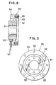
- annular member 55 Fixed to a rear end face of the metering bearing housing 41 by bolts 57 is an annular member 55 on which a resin pressure detecting element, comprised of a strain gauge 100 (Fig. 2), for instance, is mounted.
- the annular member 55 has a rear end face on which a ball nut 56, threadedly engaged with the injection ball screw 34, is fixed at its flange 58 by bolts 59. That is, the connection at one side of the annular member 55 facing the metering bearing housing 41 is independently and separately achieved from that at the other side of the same member facing the ball nut 56.
- the annular member 55 consists of an inner cylindrical section 60, an outer cylindrical section 64, and a coupling section 63 which connects the above-mentioned two sections 60, 64 into one piece.
- the inner cylindrical section 60 is formed at its central part with a through hole 61 for receiving the ball screw 34 extending therethrough, and is formed with a plurality of bolt-insertion holes 62 circumferentially of the through hole 61.
- the outer cylindrical section 64 is formed at its rear end face with a plurality of blind bolt-mounting holes 65.
- the housing 41 is formed at the rear end face with bolt-mounting holes 66 in alignment of the bolt-insertion holes 62, and the ball nut 56 is formed at its flange 58 with bolt-insertion holes 67 in alignment of the bolt-mounting holes 65, respectively.
- the respective bolt 57 is inserted through an associated one of the bolt-insertion holes 62 formed in the annular member 55, and is then screwed into an associated one of the bolt-mounting holes 66 of the metering bearing housing 41, to thereby fix the annular member 55 to the housing 41.
- the ball nut 56 is brought into contact at its flange 58 with the rear end face of the outer cylindrical section 64 of the annular member 55, with the ball nut 56 engaged with the ball screw 34 which is inserted through the through hole 61 of the annular member 55.
- the respective bolt 59 is inserted through an associated one of the bolt-insertion holes 67 of the flange 58, and is screwed into a corresponding one of the bolt-mounting holes 65 of the outer cylindrical section 64, to thereby fix the ball nut 56 to the annular member 55.
- strain gauge 100 is connected through electric wires 101 with external elements, such as a gauge amplifier and a control circuit (none of these elements illustrated), which cooperate with the gauge 100 and the annular member 55 to form a known resin pressure detecting system.
- external elements such as a gauge amplifier and a control circuit (none of these elements illustrated), which cooperate with the gauge 100 and the annular member 55 to form a known resin pressure detecting system.
- the ball screw 34 rotates to cause the forward movement of the ball nut 56, engaged therewith, along the ball screw 34.
- the pusher plate 18, fixed to the ball nut 56 through the annular member 55 and the metering bearing housing 41 is moved along the tie rods 13 in unison with the ball nut 56, and at the same time, the metering screw 22, fixed to the housing 41 through the screw sleeve 45, etc., to be axially immovable relative to the housing, is moved in unison with the ball nut 56, whereby the injection operation is carried out.
- the annular member 55 which is integrally combined with the screw 22 through the above-mentioned various elements, receives the reaction force from the resin material, and is hence slightly deformed in dependence on the resin reaction force or the injection pressure. Then, a signal, indicative of the amount of deformation, i.e., the injection pressure, is generated by the strain gauge 100.
- the output signal of the strain gauge 100 represents the accurate injection pressure, and no particular correction such as zero adjustment is required.
- the hold pressure is detected in a similar manner.
- the metering pulley 51 is driven by the servomotor, not shown, to cause the rotation of the metering screw 22 for execution of the metering process, wherein the back pressure is detected in a similar manner.
- pressure control is effected in a conventional manner on the basis of the thus detected various resin pressure.
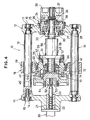
- Fig. 4 shows part of an injection molding machine according to a second embodiment of the present invention.
- this injection molding machine is slightly different therefrom in construction of a metering bearing housing and a screw sleeve, and differs in a mechanism for supporting the sleeve in the housing in a manner permitting relative rotation and preventing relative axial movement. That is, referring to Fig.
- a radial ball bearing 70 and a thrust ball bearing 71 are disposed at one side of the housing 41' facing the front plate 11 with respect to the partition wall 41′a, and an angular ball bearing 72 is disposed at the other side of the housing facing the rear plate 12, respectively.
- a screw sleeve 45′ is supported by the housing 41′ through the above-mentioned bearings.
Landscapes
- Engineering & Computer Science (AREA)
- Manufacturing & Machinery (AREA)
- Mechanical Engineering (AREA)
- Injection Moulding Of Plastics Or The Like (AREA)
Abstract
Claims (3)
- Machine de moulage par injection comportant une unité d'injection (10) qui englobe un logement (41) supportant un dispositif de dosage, disposé pour effectuer un mouvement à l'unisson avec une vis de dosage (22), un mécanisme de vis à billes/écrou (34, 56) permettant à la vis de dosage (22) d'effectuer un mouvement de va-et-vient à travers le logement (41), ainsi qu'un élément annulaire (55) sur lequel est monté un élément (100) de détection de pression de résine, caractérisée par :
un premier moyen de fixation (57) pour fixer ledit élément annulaire (55) sur la face externe du logement (41) supportant un dispositif de dosage du côté éloigné de la vis de dosage (22); et
un second moyen de fixation (58, 59) pour fixer un écrou sphérique (56) du mécanisme de vis à billes/écrou (34, 56) sur la face externe dudit élément annulaire (55) du côté éloigné du logement (41) supportant le dispositif de dosage. - Machine de moulage par injection dotée d'une fonction de détection de pression de résine, selon la revendication 1, dans laquelle ledit élément (100) de détection de pression de résine comprend une jauge de contrainte.
- Machine de moulage par injection dotée d'une fonction de détection de pression de résine, selon la revendication 1 ou 2, dans laquelle ledit élément annulaire (55) englobe une section cylindrique interne (60) dans laquelle est pratiqué un premier groupe de trous d'insertion de boulons (62) en position circonférentielle à cette section, une section cylindrique externe (64) comportant une face terminale, du côté proche dudit écrou sphérique (56), dans laquelle est pratiqué un premier groupe de trous de montage de boulons (65) disposés circonférentiellement à cette section, ainsi qu'une section de couplage (63) reliant lesdites sections cylindriques interne et externe (60, 64) en une seule pièce; ledit logement (41) supportant le dispositif de dosage comportant une face terminale, du côté proche dudit élément annulaire (55), dans laquelle est pratiqué un second groupe de trous de montage de boulons (66) en alignement avec ledit premier groupe de trous d'insertion de boulons (62); ledit écrou sphérique (56) comportant une portion marginale circonférentielle (58) dans laquelle est pratiqué un second groupe de trous d'insertion de boulons (67) en alignement avec ledit premier groupe de trous de montage de boulons (65); ledit premier moyen de fixation comprenant ledit premier groupe de trous d'insertion de boulons (62), ledit second groupe de trous de montage de boulons (66), ainsi qu'un premier groupe de boulons (57) qui leur est associé; et ledit second moyen de fixation comprenant ledit second groupe de trous d'insertion de boulons (67), ledit premier groupe de trous de montage de boulons (65), ainsi qu'un second groupe de boulons (59) qui leur est associé.
Applications Claiming Priority (2)
| Application Number | Priority Date | Filing Date | Title |
|---|---|---|---|
| JP62183449A JPH0696251B2 (ja) | 1987-07-24 | 1987-07-24 | 射出成形機 |
| JP183449/87 | 1987-07-24 |
Publications (3)
| Publication Number | Publication Date |
|---|---|
| EP0331735A1 EP0331735A1 (fr) | 1989-09-13 |
| EP0331735A4 EP0331735A4 (en) | 1990-10-24 |
| EP0331735B1 true EP0331735B1 (fr) | 1993-09-15 |
Family
ID=16135970
Family Applications (1)
| Application Number | Title | Priority Date | Filing Date |
|---|---|---|---|
| EP88906125A Expired - Lifetime EP0331735B1 (fr) | 1987-07-24 | 1988-07-22 | Machine de moulage par injection comportant une fonction de detection de la pression de resine |
Country Status (7)
| Country | Link |
|---|---|
| US (1) | US4961696A (fr) |
| EP (1) | EP0331735B1 (fr) |
| JP (1) | JPH0696251B2 (fr) |
| KR (1) | KR960015300B1 (fr) |
| CA (1) | CA1294103C (fr) |
| DE (1) | DE3884184T2 (fr) |
| WO (1) | WO1989000915A1 (fr) |
Cited By (2)
| Publication number | Priority date | Publication date | Assignee | Title |
|---|---|---|---|---|
| DE19525142C1 (de) * | 1995-07-11 | 1996-10-31 | Karl Hehl | Verfahren zur Erfassung der an einer Spritzgießmaschine auftretenden Kräfte sowie Vorrichtung zur Durchführung des Verfahrens |
| DE19525141C1 (de) * | 1995-07-11 | 1996-11-28 | Karl Hehl | Verfahren zur Regelung oder Steuerung einer Kunststoff-Spritzgießmaschine |
Families Citing this family (27)
| Publication number | Priority date | Publication date | Assignee | Title |
|---|---|---|---|---|
| JPH0661801B2 (ja) * | 1988-07-13 | 1994-08-17 | 住友重機械工業株式会社 | 電動射出成形機のモータ制御装置 |
| US5102587A (en) * | 1989-07-26 | 1992-04-07 | Canon Kabushiki Kaisha | Injection mold using screw thrust control |
| JPH0477226A (ja) * | 1990-07-18 | 1992-03-11 | Nissei Plastics Ind Co | 射出成形機 |
| JPH0477225A (ja) * | 1990-07-18 | 1992-03-11 | Nissei Plastics Ind Co | 射出成形機 |
| JPH0735077B2 (ja) * | 1990-09-20 | 1995-04-19 | 日精樹脂工業株式会社 | 射出成形機 |
| US5360331A (en) * | 1993-01-05 | 1994-11-01 | Dynisco, Inc. | Injection molding machine pressure transducer |
| JP3318427B2 (ja) * | 1994-01-21 | 2002-08-26 | ファナック株式会社 | 射出成形機における圧力検出装置の零点補正方法 |
| US5602339A (en) * | 1994-03-24 | 1997-02-11 | Dynisco, Inc. | Injection molding machine pressure transducer with trapezoidal cavity |
| JP2838647B2 (ja) * | 1994-05-16 | 1998-12-16 | 住友重機械工業株式会社 | 射出成形機におけるエジェクタ機構のエジェクタ戻限完了位置設定方法及び装置 |
| JP2754356B2 (ja) * | 1995-01-19 | 1998-05-20 | ファナック株式会社 | 射出成形機の射出機構 |
| US5645868A (en) * | 1995-11-17 | 1997-07-08 | Cincinnati Milacron Inc. | Drive apparatus for an injection unit |
| JP3502545B2 (ja) * | 1998-06-26 | 2004-03-02 | 住友重機械工業株式会社 | 射出装置 |
| US6149418A (en) * | 1999-04-16 | 2000-11-21 | Milacron Inc. | Dual motor drive system for an injection molding machine |
| EP1151843B1 (fr) * | 2000-05-02 | 2003-02-19 | Engel Maschinenbau Gesellschaft Mbh | Unité d'injection pour une machine à mouler par injection |
| TW454687U (en) * | 2000-08-11 | 2001-09-11 | Ind Tech Res Inst | Injection and metering sensing devices for an injection molding machine |
| DE10114006C2 (de) * | 2001-03-22 | 2003-07-17 | Siemens Ag | Kunststoffspritzgießmaschine |
| AT5443U1 (de) * | 2001-07-09 | 2002-07-25 | Engel Gmbh Maschbau | Einrichtung zur kraft- bzw. drucküberwachung bei spritzgiessmaschinen |
| US6695994B2 (en) * | 2001-09-29 | 2004-02-24 | Van Dorn Demag Corporation | Melt pressure observer for electric injection molding machine |
| DE10210923B4 (de) * | 2002-03-13 | 2004-08-12 | Demag Ergotech Gmbh | Druckmesseinrichtung für eine Spritzgießmaschine |
| JP2004358902A (ja) * | 2003-06-06 | 2004-12-24 | Fanuc Ltd | 射出成形機の射出機構 |
| JP4582520B2 (ja) * | 2005-01-13 | 2010-11-17 | 株式会社ニイガタマシンテクノ | 射出成形機の射出装置 |
| DE102005012337B3 (de) * | 2005-03-17 | 2006-03-16 | Mannesmann Plastics Machinery Gmbh | Antriebssystem für eine Plastifiziereinheit einer Spritzgießmaschine |
| US20080299244A1 (en) * | 2007-05-29 | 2008-12-04 | Husky Injection Molding Systems Ltd. | Apparatus and Method for Producing Optical Molded Parts |
| JP2009061656A (ja) * | 2007-09-06 | 2009-03-26 | Sumitomo Heavy Ind Ltd | 射出装置 |
| DE102009053043A1 (de) * | 2009-11-16 | 2011-05-19 | Baumer Innotec Ag | Kraftmesszelle zur Messung der Einspritzkraft beim Spritzgießen |
| US11821782B2 (en) * | 2020-09-17 | 2023-11-21 | Delta Electronics, Inc. | Load cell for measuring a loading force under a specific range with limitation element to prevent irreversible deformation |
| JP7697304B2 (ja) * | 2021-07-28 | 2025-06-24 | セイコーエプソン株式会社 | 可塑化装置、三次元造形装置および射出成形装置 |
Family Cites Families (8)
| Publication number | Priority date | Publication date | Assignee | Title |
|---|---|---|---|---|
| DE2454193A1 (de) * | 1974-11-15 | 1976-05-20 | Kautex Werke Gmbh | Vorrichtung zum herstellen von formlingen aus thermoplastischem kunststoff |
| JPS6131221A (ja) * | 1984-07-24 | 1986-02-13 | Nissei Plastics Ind Co | 射出成形機における背圧力制御方法 |
| JPS61195819A (ja) * | 1985-02-26 | 1986-08-30 | Niigata Eng Co Ltd | 射出成形機における圧力制御装置 |
| JPS61235119A (ja) * | 1985-04-12 | 1986-10-20 | Nissei Plastics Ind Co | 射出成形機の射出制御方法及び装置 |
| JPS6244417A (ja) * | 1985-08-23 | 1987-02-26 | Toyoda Autom Loom Works Ltd | 射出成形機のスクリュ−推力制御方法 |
| JPS6297818A (ja) * | 1985-10-25 | 1987-05-07 | Fanuc Ltd | 射出成形機における樹脂圧力制御装置 |
| JPS62218118A (ja) * | 1986-03-20 | 1987-09-25 | Fanuc Ltd | 射出成形機の射出制御装置 |
| JPH06244417A (ja) * | 1993-02-15 | 1994-09-02 | Sharp Corp | 薄膜トランジスタおよびその製造方法 |
-
1987
- 1987-07-24 JP JP62183449A patent/JPH0696251B2/ja not_active Expired - Lifetime
-
1988
- 1988-07-22 DE DE88906125T patent/DE3884184T2/de not_active Expired - Fee Related
- 1988-07-22 EP EP88906125A patent/EP0331735B1/fr not_active Expired - Lifetime
- 1988-07-22 WO PCT/JP1988/000741 patent/WO1989000915A1/fr not_active Ceased
- 1988-07-22 KR KR1019890700530A patent/KR960015300B1/ko not_active Expired - Lifetime
- 1988-07-22 US US07/329,787 patent/US4961696A/en not_active Expired - Lifetime
- 1988-07-22 CA CA000572889A patent/CA1294103C/fr not_active Expired - Lifetime
Cited By (2)
| Publication number | Priority date | Publication date | Assignee | Title |
|---|---|---|---|---|
| DE19525142C1 (de) * | 1995-07-11 | 1996-10-31 | Karl Hehl | Verfahren zur Erfassung der an einer Spritzgießmaschine auftretenden Kräfte sowie Vorrichtung zur Durchführung des Verfahrens |
| DE19525141C1 (de) * | 1995-07-11 | 1996-11-28 | Karl Hehl | Verfahren zur Regelung oder Steuerung einer Kunststoff-Spritzgießmaschine |
Also Published As
| Publication number | Publication date |
|---|---|
| US4961696A (en) | 1990-10-09 |
| DE3884184T2 (de) | 1994-01-13 |
| CA1294103C (fr) | 1992-01-14 |
| EP0331735A4 (en) | 1990-10-24 |
| JPH0696251B2 (ja) | 1994-11-30 |
| WO1989000915A1 (fr) | 1989-02-09 |
| KR960015300B1 (ko) | 1996-11-07 |
| JPS6427921A (en) | 1989-01-30 |
| DE3884184D1 (de) | 1993-10-21 |
| EP0331735A1 (fr) | 1989-09-13 |
| KR890701321A (ko) | 1989-12-20 |
Similar Documents
| Publication | Publication Date | Title |
|---|---|---|
| US4961696A (en) | Injection molding machine with a resin pressure detecting function | |
| US6186268B1 (en) | Electric power steering unit | |
| JPH0477225A (ja) | 射出成形機 | |
| US5597965A (en) | Method and apparatus for measuring the preload gap of a double row rolling bearing | |
| US20210218314A1 (en) | Electric motor having a rotor shaft and a first and a second bearing | |
| CN114439866B (zh) | 一种高精度带液压刹车结构的转台 | |
| US6276838B1 (en) | Shaft-hub assembly and method of production thereof | |
| JP2631132B2 (ja) | 射出成形機 | |
| JPH06300046A (ja) | 軸あるいは車軸を支持部内に支持するための軸受装置 | |
| US5209936A (en) | Injection molding machine having a load cell for detecting a pressure applied to a screw coupling | |
| JP5348486B2 (ja) | エンコーダ付モータ | |
| EP0981690B1 (fr) | Pompe a vide a systeme de palier magnetique et a paliers amortisseurs | |
| US6225721B1 (en) | Self-centering timing disk hub and method of mounting the same | |
| KR20100075578A (ko) | 베어링 장치 | |
| CN113550798B (zh) | 低压涡轮转、静子轴向间隙控制方法及装置 | |
| JP4533341B2 (ja) | 射出成形機の駆動機構 | |
| US20020034560A1 (en) | Sensing and reckoning mechanism for injection machine | |
| JP7489235B2 (ja) | 回転機械 | |
| JP4533340B2 (ja) | 射出成形機の駆動機構 | |
| US5803618A (en) | Compound ball bearing | |
| JP2685134B2 (ja) | 軸受キャップの組付方法 | |
| JPH02164241A (ja) | アンギュラコンタクト形組合わせ玉軸受の予圧量検出装置 | |
| JP2001200841A (ja) | 軸受装置における軸受の異常検知装置 | |
| JP4486613B2 (ja) | 射出成形機の駆動機構 | |
| EP0041278B1 (fr) | Rondelle de fixation |
Legal Events
| Date | Code | Title | Description |
|---|---|---|---|
| PUAI | Public reference made under article 153(3) epc to a published international application that has entered the european phase |
Free format text: ORIGINAL CODE: 0009012 |
|
| 17P | Request for examination filed |
Effective date: 19890330 |
|
| AK | Designated contracting states |
Kind code of ref document: A1 Designated state(s): CH DE FR GB IT LI |
|
| A4 | Supplementary search report drawn up and despatched |
Effective date: 19900905 |
|
| AK | Designated contracting states |
Kind code of ref document: A4 Designated state(s): CH DE FR GB IT LI |
|
| 17Q | First examination report despatched |
Effective date: 19920107 |
|
| ITF | It: translation for a ep patent filed | ||
| GRAA | (expected) grant |
Free format text: ORIGINAL CODE: 0009210 |
|
| AK | Designated contracting states |
Kind code of ref document: B1 Designated state(s): CH DE FR GB IT LI |
|
| PG25 | Lapsed in a contracting state [announced via postgrant information from national office to epo] |
Ref country code: FR Effective date: 19930915 |
|
| REF | Corresponds to: |
Ref document number: 3884184 Country of ref document: DE Date of ref document: 19931021 |
|
| EN | Fr: translation not filed | ||
| PLBE | No opposition filed within time limit |
Free format text: ORIGINAL CODE: 0009261 |
|
| STAA | Information on the status of an ep patent application or granted ep patent |
Free format text: STATUS: NO OPPOSITION FILED WITHIN TIME LIMIT |
|
| PG25 | Lapsed in a contracting state [announced via postgrant information from national office to epo] |
Ref country code: GB Effective date: 19940722 |
|
| 26N | No opposition filed | ||
| GBPC | Gb: european patent ceased through non-payment of renewal fee |
Effective date: 19940722 |
|
| PGFP | Annual fee paid to national office [announced via postgrant information from national office to epo] |
Ref country code: DE Payment date: 20000717 Year of fee payment: 13 |
|
| PGFP | Annual fee paid to national office [announced via postgrant information from national office to epo] |
Ref country code: CH Payment date: 20000726 Year of fee payment: 13 |
|
| PG25 | Lapsed in a contracting state [announced via postgrant information from national office to epo] |
Ref country code: LI Free format text: LAPSE BECAUSE OF NON-PAYMENT OF DUE FEES Effective date: 20010731 Ref country code: CH Free format text: LAPSE BECAUSE OF NON-PAYMENT OF DUE FEES Effective date: 20010731 |
|
| REG | Reference to a national code |
Ref country code: CH Ref legal event code: PL |
|
| PG25 | Lapsed in a contracting state [announced via postgrant information from national office to epo] |
Ref country code: DE Free format text: LAPSE BECAUSE OF NON-PAYMENT OF DUE FEES Effective date: 20020501 |
|
| PG25 | Lapsed in a contracting state [announced via postgrant information from national office to epo] |
Ref country code: IT Free format text: LAPSE BECAUSE OF NON-PAYMENT OF DUE FEES Effective date: 20050722 |