EP0331801A1 - Roue de guidage de ruban pour l'insertion de la trame dans un métier à tisser - Google Patents
Roue de guidage de ruban pour l'insertion de la trame dans un métier à tisser Download PDFInfo
- Publication number
- EP0331801A1 EP0331801A1 EP88120040A EP88120040A EP0331801A1 EP 0331801 A1 EP0331801 A1 EP 0331801A1 EP 88120040 A EP88120040 A EP 88120040A EP 88120040 A EP88120040 A EP 88120040A EP 0331801 A1 EP0331801 A1 EP 0331801A1
- Authority
- EP
- European Patent Office
- Prior art keywords
- wheel
- belt
- weft insertion
- band
- spiral
- Prior art date
- Legal status (The legal status is an assumption and is not a legal conclusion. Google has not performed a legal analysis and makes no representation as to the accuracy of the status listed.)
- Withdrawn
Links
Images

Classifications
-
- D—TEXTILES; PAPER
- D03—WEAVING
- D03D—WOVEN FABRICS; METHODS OF WEAVING; LOOMS
- D03D47/00—Looms in which bulk supply of weft does not pass through shed, e.g. shuttleless looms, gripper shuttle looms, dummy shuttle looms
- D03D47/27—Drive or guide mechanisms for weft inserting
- D03D47/271—Rapiers
- D03D47/272—Rapier bands
-
- D—TEXTILES; PAPER
- D03—WEAVING
- D03D—WOVEN FABRICS; METHODS OF WEAVING; LOOMS
- D03D47/00—Looms in which bulk supply of weft does not pass through shed, e.g. shuttleless looms, gripper shuttle looms, dummy shuttle looms
- D03D47/27—Drive or guide mechanisms for weft inserting
- D03D47/275—Drive mechanisms
- D03D47/276—Details or arrangement of sprocket wheels
Definitions
- the present invention relates to a belt wheel for weft insertion on a weaving machine, which has a wheel hub and a wheel body connected to it with a wheel rim and a support part fastened to the wheel rim with a tread for receiving a weft insertion belt and a fastening device for the weft insertion belt.
- the entry or weaving width of the machine is limited. A change in this then also requires a change in the belt length and, with the diameter of the belt wheel remaining the same, a change in the angle of rotation of the belt wheel.
- the entry width is increased and the length of the weft insertion belt is lengthened, the belt wheel must then be over-rotated beyond one full rotation, which leads to the weft belt being overwound on the belt wheel.
- the end of the weft insertion tape is wound over the tape wheel, blows occur each time the tape is wound or unwound.
- the object is achieved according to the invention for the belt wheel of the type mentioned in the introduction in that the running surface for the weft insertion belt runs around the belt wheel in the form of a spiral.
- the tape wheel according to the invention enables the weft insertion tape to be wound over it without the occurrence of impacts. This makes it possible to build the belt wheel smaller and thereby improve the dynamic conditions; it can be accelerated and decelerated more quickly, thus increasing the total input capacity.
- the continuous build-up of the weft insertion tape on the running surface of the tape edge and its service life are thus improved. This enables small wall thicknesses and a lower moment of inertia for the belt wheel.
- the speed ver Run is at the tape entry according to the invention without disruption due to a so-called paragraph due to winding the weft insertion tape and jumps in speed when the weft insertion tape runs up or down are avoided.
- the weft insertion numbers can thus also be increased with a more favorable dimensioning of the wheel.
- the band wheel according to the invention allows a variable weft width without the occurrence of blows from overwinding.
- a spiral is a curve whose radius vector is a function of the angle of rotation (see, for example, Mathematik Ratgeber, Verlag Harri Deutsch, Zurich 1974, page 454). It is advantageous if the spiral has a radial deviation around the circumference of the wheel body, ie a change in the radius vector which corresponds to at least one thickness of the weft insertion band.
- the ra extends diale deviation preferably almost around the entire circumference of the belt wheel, the radius vector decreasing from a point of impact of the weft insertion belt onto the belt wheel. This avoids a jump in the winding of the weft insertion tape at the winding point thereof.
- the radial deviation is preferably chosen to be greater than the thickness of the weft insertion band because the tension band still lies over the weft insertion band.
- the radial deviation of the spiral can be generated by changing the thickness of the support part, the thickness of the support part preferably decreasing away from the contact point of the weft input strip onto the tread, viewed in the direction of the weft insertion belt.
- the radial deviation of the spiral can also e.g. with the thickness of the support part remaining the same, being caused by changing the radius of the wheel rim, the radius of the wheel rim preferably decreasing away from a point of impact of the weft belt onto the tread, as viewed in the direction of the weft insertion belt.
- the spiral shape of the tread preferably extends over the major part of the circumference of the wheel body, for example from one side to the other side of a fastening device with which the weft insertion band is fastened at one end to the band wheel.
- the remaining parts of the band wheel according to the invention can be designed as desired, for which purpose e.g. to the CH-PS 629'895 or the CH-PS (corresponding to CH patent application No. (not yet known) dated March 9, 1988, titled “tape wheel for weft insertion on a weaving machine”).
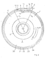
- the band wheel 1 has a wheel hub 2 and a wheel body 3 with an outer wheel rim 4 and can be rotatably supported about an axis of rotation A with the wheel hub 2.
- the wheel body 3 also has an indentation 8 for receiving one end 9 of the weft insertion belt 7, which extends over part of the circumference of the wheel body 3.
- the weft insertion band 7 is in the indentation or depression 8 on the wheel body 3 by means of a fastening device 10 attached.
- the belt wheel 1 can be driven in the direction of arrows B and C, for example from the center, which correspond to a running direction B or a running direction C of the weft insertion belt 7 on the wheel body 3.
- the support part 5 has on the leading side 11 in the upward direction B of the indentation 8 a thickness D 1 which is greater than a thickness D 2 on the trailing side B in the upward direction 12 of the indentation 8, so that the thickness of the supporting part 5 in the upward direction B viewed from one Ramp point or a run-up point 13 of the weft insertion tape 7 on the running surface 6 decreases.
- the tread 6 therefore has a radius r 1, seen in the direction of travel B on the leading side 11, which is larger than a radius r 2 on the trailing side 12 of the indentation 8.
- the difference between the radii r 1 and r 2 corresponds to a thickness E of the weft insertion belt 7
- the tread 6 around the belt wheel 1 has the shape of a spiral 14.
- the radius vector of the tread 6 increases continuously in the direction of travel or rotation C from the trailing side 12 to the leading side 11 of the indentation 8.
- a filler 15 is provided to bridge the indentation 8.
- the weft insertion belt 7 runs up at the run-up point 13 and winds up on the running surface 6 on the support part 5.
- the weft insertion belt 7 can lie on the run-up point 13, without being abruptly raised, on the part of the weft insertion belt 7 that has already been wound up. As a result, a sudden lifting of the weft insertion belt 7 at the run-up point 13 and thus a blow on the belt wheel 1 is avoided.
- FIG. 2 in which parts that are the same as those in FIG. 1 have the same reference numerals, shows a band wheel 20 with a wheel rim 21 and a support part 22 with a constant thickness F over the full circumference of the band wheel 20.
- the wheel rim 21 has the leading end, viewed in the direction of run B.
- Side 11 of the indentation 8 has a radius r3 which is greater than a radius r4 on the trailing side 12 of the indentation 8.
- the radius vector changes in the run-up direction B of the belt wheel between the leading side 11 and the trailing side 12 of the indentation 8.
- the radius vector of the wheel rim 21 continuously decreases from the leading side 11 to the trailing side 12 in the running direction B, so that the tread 23 for the weft insertion belt 7 on the Support part 22 extends around the band wheel 20 in the form of a spiral 24.
- the radius vector of the wheel rim 21 and thus the tread 23, viewed in the direction of discharge C increases continuously from the trailing side 12 to the leading side 11 of the indentation 8.
- the band wheel 20 with the wheel rim 21 therefore has the same conditions as were described above for the band wheel 1 of FIG. 1.
Landscapes
- Engineering & Computer Science (AREA)
- Textile Engineering (AREA)
- Looms (AREA)
Applications Claiming Priority (2)
| Application Number | Priority Date | Filing Date | Title |
|---|---|---|---|
| CH88488 | 1988-03-09 | ||
| CH884/88 | 1988-03-09 |
Publications (1)
| Publication Number | Publication Date |
|---|---|
| EP0331801A1 true EP0331801A1 (fr) | 1989-09-13 |
Family
ID=4197418
Family Applications (1)
| Application Number | Title | Priority Date | Filing Date |
|---|---|---|---|
| EP88120040A Withdrawn EP0331801A1 (fr) | 1988-03-09 | 1988-12-01 | Roue de guidage de ruban pour l'insertion de la trame dans un métier à tisser |
Country Status (2)
| Country | Link |
|---|---|
| EP (1) | EP0331801A1 (fr) |
| JP (1) | JPH01272848A (fr) |
Citations (2)
| Publication number | Priority date | Publication date | Assignee | Title |
|---|---|---|---|---|
| EP0080191A1 (fr) * | 1981-11-20 | 1983-06-01 | Helmut Meinunger | Dispositif d'enroulement d'un écran de projection |
| EP0253184A1 (fr) * | 1986-07-15 | 1988-01-20 | GebràDer Sulzer Aktiengesellschaft | Dispositif pour l'insertion du fil de trame dans un métier à tisser à griffes |
-
1988
- 1988-12-01 EP EP88120040A patent/EP0331801A1/fr not_active Withdrawn
-
1989
- 1989-03-09 JP JP1055251A patent/JPH01272848A/ja active Pending
Patent Citations (2)
| Publication number | Priority date | Publication date | Assignee | Title |
|---|---|---|---|---|
| EP0080191A1 (fr) * | 1981-11-20 | 1983-06-01 | Helmut Meinunger | Dispositif d'enroulement d'un écran de projection |
| EP0253184A1 (fr) * | 1986-07-15 | 1988-01-20 | GebràDer Sulzer Aktiengesellschaft | Dispositif pour l'insertion du fil de trame dans un métier à tisser à griffes |
Also Published As
| Publication number | Publication date |
|---|---|
| JPH01272848A (ja) | 1989-10-31 |
Similar Documents
| Publication | Publication Date | Title |
|---|---|---|
| DE2451400C2 (de) | Wickelvorrichtung | |
| EP0319921A2 (fr) | Dispositif de guidage d'une bande de forme bombée | |
| EP0450620A1 (fr) | Tendeur automatique de courroies | |
| DE2516792C2 (de) | Haspelanordnung | |
| EP1491488B1 (fr) | Appareil de levage | |
| DE10321729A1 (de) | Gurtaufroller für einen Fahrzeug-Sicherheitsgurt | |
| EP0375322A2 (fr) | Moyeu de bobine à bande | |
| EP2047142B1 (fr) | Poulie de renvoi avec meilleure utilisation de la chaine | |
| DE2511855C3 (de) | Schwungrad mit mehreren Kränzen aus anisotropem Material | |
| DE3810967A1 (de) | Wickelspule | |
| EP0754505B1 (fr) | Dispositif d'enroulement | |
| CH471988A (de) | Einrichtung mit einem Klinkenrad und mindestens einem zu seinem Antrieb dienenden Schwingorgan | |
| DE102004054033B3 (de) | Weitwurfspule für Angelrollen | |
| DE2332460A1 (de) | Bremsvorrichtung fuer fahrzeuge | |
| EP0253184A1 (fr) | Dispositif pour l'insertion du fil de trame dans un métier à tisser à griffes | |
| DE2728155C2 (de) | Vorrichtung zum Verhindern des vollständigen Abrollens eines Fahrzeugsicherheitsgurtes von der Wickelachse eines Gurtaufrollers | |
| DE60110259T2 (de) | System zum aufwickeln von bandmaterial aus aluminium und zugehörige methode | |
| DE2923691A1 (de) | Vorrichtung fuer eine spiralfeder | |
| EP0190626A2 (fr) | Dispositif de commande de l'axe basculant d'un store vénitien | |
| EP0710617B1 (fr) | Cylindre creux à longueur variable | |
| DE4411447C2 (de) | Wickeleinrichtung | |
| DE2913362C2 (de) | Rillenwalze für die Entwässerung einer Materialbahn | |
| DD218340A5 (de) | Winde | |
| DE2165798B2 (de) | Vorrichtung zum kontinuierlichen ueberleiten von stranggut, insbesondere von draht | |
| DE2255607C3 (fr) |
Legal Events
| Date | Code | Title | Description |
|---|---|---|---|
| PUAI | Public reference made under article 153(3) epc to a published international application that has entered the european phase |
Free format text: ORIGINAL CODE: 0009012 |
|
| AK | Designated contracting states |
Kind code of ref document: A1 Designated state(s): BE CH DE IT LI |
|
| STAA | Information on the status of an ep patent application or granted ep patent |
Free format text: STATUS: THE APPLICATION IS DEEMED TO BE WITHDRAWN |
|
| 18D | Application deemed to be withdrawn |
Effective date: 19900314 |