EP0331843A1 - Distributeur d'adhésif - Google Patents
Distributeur d'adhésif Download PDFInfo
- Publication number
- EP0331843A1 EP0331843A1 EP88311134A EP88311134A EP0331843A1 EP 0331843 A1 EP0331843 A1 EP 0331843A1 EP 88311134 A EP88311134 A EP 88311134A EP 88311134 A EP88311134 A EP 88311134A EP 0331843 A1 EP0331843 A1 EP 0331843A1
- Authority
- EP
- European Patent Office
- Prior art keywords
- adhesive
- applicator
- dispenser according
- dispenser
- rotatable member
- Prior art date
- Legal status (The legal status is an assumption and is not a legal conclusion. Google has not performed a legal analysis and makes no representation as to the accuracy of the status listed.)
- Withdrawn
Links
- 239000000853 adhesive Substances 0.000 title claims abstract description 76
- 230000001070 adhesive effect Effects 0.000 title claims abstract description 76
- 230000009471 action Effects 0.000 claims description 8
- 239000003292 glue Substances 0.000 description 29
- 239000000463 material Substances 0.000 description 9
- 239000007788 liquid Substances 0.000 description 6
- 239000002313 adhesive film Substances 0.000 description 3
- 239000011111 cardboard Substances 0.000 description 3
- 210000000078 claw Anatomy 0.000 description 3
- 238000004026 adhesive bonding Methods 0.000 description 2
- 230000008859 change Effects 0.000 description 2
- 229920001971 elastomer Polymers 0.000 description 2
- 238000001704 evaporation Methods 0.000 description 2
- 230000008020 evaporation Effects 0.000 description 2
- 230000005484 gravity Effects 0.000 description 2
- 230000001788 irregular Effects 0.000 description 2
- 239000002184 metal Substances 0.000 description 2
- 239000000123 paper Substances 0.000 description 2
- 238000003825 pressing Methods 0.000 description 2
- 239000005060 rubber Substances 0.000 description 2
- 235000010585 Ammi visnaga Nutrition 0.000 description 1
- 244000153158 Ammi visnaga Species 0.000 description 1
- 239000004825 One-part adhesive Substances 0.000 description 1
- 239000004826 Synthetic adhesive Substances 0.000 description 1
- 239000012790 adhesive layer Substances 0.000 description 1
- 230000008901 benefit Effects 0.000 description 1
- 238000010276 construction Methods 0.000 description 1
- 230000001419 dependent effect Effects 0.000 description 1
- 230000000994 depressogenic effect Effects 0.000 description 1
- 238000001035 drying Methods 0.000 description 1
- 239000013536 elastomeric material Substances 0.000 description 1
- 239000003822 epoxy resin Substances 0.000 description 1
- 239000004744 fabric Substances 0.000 description 1
- 229920002457 flexible plastic Polymers 0.000 description 1
- 230000009969 flowable effect Effects 0.000 description 1
- 239000010410 layer Substances 0.000 description 1
- 230000014759 maintenance of location Effects 0.000 description 1
- 229910001092 metal group alloy Inorganic materials 0.000 description 1
- 239000000203 mixture Substances 0.000 description 1
- 229920001206 natural gum Polymers 0.000 description 1
- 239000011087 paperboard Substances 0.000 description 1
- 230000037361 pathway Effects 0.000 description 1
- 239000004033 plastic Substances 0.000 description 1
- 229920003023 plastic Polymers 0.000 description 1
- 229920000647 polyepoxide Polymers 0.000 description 1
- -1 polytetrafluoroethylene Polymers 0.000 description 1
- 229920001343 polytetrafluoroethylene Polymers 0.000 description 1
- 239000004810 polytetrafluoroethylene Substances 0.000 description 1
- 230000001681 protective effect Effects 0.000 description 1
- 238000005096 rolling process Methods 0.000 description 1
- 239000007787 solid Substances 0.000 description 1
- 230000007480 spreading Effects 0.000 description 1
- 239000000126 substance Substances 0.000 description 1
- 239000000758 substrate Substances 0.000 description 1
- XLYOFNOQVPJJNP-UHFFFAOYSA-N water Substances O XLYOFNOQVPJJNP-UHFFFAOYSA-N 0.000 description 1
Images


Classifications
-
- B—PERFORMING OPERATIONS; TRANSPORTING
- B43—WRITING OR DRAWING IMPLEMENTS; BUREAU ACCESSORIES
- B43M—BUREAU ACCESSORIES NOT OTHERWISE PROVIDED FOR
- B43M11/00—Hand or desk devices of the office or personal type for applying liquid, other than ink, by contact to surfaces, e.g. for applying adhesive
- B43M11/06—Hand-held devices
- B43M11/08—Hand-held devices of the fountain-pen type
- B43M11/085—Hand-held devices of the fountain-pen type with ball points
-
- A—HUMAN NECESSITIES
- A45—HAND OR TRAVELLING ARTICLES
- A45D—HAIRDRESSING OR SHAVING EQUIPMENT; EQUIPMENT FOR COSMETICS OR COSMETIC TREATMENTS, e.g. FOR MANICURING OR PEDICURING
- A45D34/00—Containers or accessories specially adapted for handling liquid toiletry or cosmetic substances, e.g. perfumes
- A45D34/04—Appliances specially adapted for applying liquid, e.g. using roller or ball
- A45D34/041—Appliances specially adapted for applying liquid, e.g. using roller or ball using a roller, a disc or a ball
-
- B—PERFORMING OPERATIONS; TRANSPORTING
- B43—WRITING OR DRAWING IMPLEMENTS; BUREAU ACCESSORIES
- B43K—IMPLEMENTS FOR WRITING OR DRAWING
- B43K1/00—Nibs; Writing-points
- B43K1/08—Nibs; Writing-points with ball points; Balls or ball beds
- B43K1/086—Nibs; Writing-points with ball points; Balls or ball beds with resilient supporting means for the ball, e.g. springs
-
- B—PERFORMING OPERATIONS; TRANSPORTING
- B43—WRITING OR DRAWING IMPLEMENTS; BUREAU ACCESSORIES
- B43K—IMPLEMENTS FOR WRITING OR DRAWING
- B43K7/00—Ball-point pens
-
- B—PERFORMING OPERATIONS; TRANSPORTING
- B43—WRITING OR DRAWING IMPLEMENTS; BUREAU ACCESSORIES
- B43K—IMPLEMENTS FOR WRITING OR DRAWING
- B43K8/00—Pens with writing-points other than nibs or balls
- B43K8/20—Pens with writing-points other than nibs or balls with roller writing-points
Definitions
- the present invention relates to adhesive dispensers for the application of a uniform adhesive film on to a surface.
- the present invention is directed to an adhesive dispenser for sticking together paper, cardboard or other similar materials.
- Certain synthetic adhesives are stored and dispensed from adhesive flasks which are substantially elongate with a tapered upper part or dispensing nozzle.
- the adhesive By pressing the flask which is normally formed of a flexible plastics material, the adhesive is forced out of the nozzle in the form of a filament.
- the adhesive is a viscous liquid and is dispensed as a filament having an irregular thickness.
- More adhesive than is normally required tends to be dispensed by pressing the flexible flask and when the two parts being glued are pressed together any excess adhesive may be expelled from between the two surfaces being glued, for example, on to a document inside the envelope as the flap of the same envelope is being glued.
- the adhesive tends to dry out in the dispensing nozzle and therefore, the nozzle needs to be unclogged before each use, for example by using a piece of metal wire or a toothpick.
- Another type of glue dispenser comprises a thin-necked bottle topped with a piece of gauze or fabric, or with a rubber cover provided with an opening for dispensing the glue. Again these devices suffer from the drying out of the glue in the neck of the bottle, and they do not provide means which effectively controls the width of the glue film being applied to a surface.
- Solid stick adhesives although overcoming the problem of irregular spreading of the adhesive on the surface, do not solve the problem of applying a uniform film of adhesive. In fact, the adhesive film is generally wider than necessary, e.g. that required for closing an envelope flap.
- a commonly used device comprises a cylindrical body which is rotatable about its longitudinal axis and which is partially immersed in a glue reservoir so that only a part of its surface is wetted by the glue, and exposed for use.
- the cylindrical body must be rotated in the glue reservoir to expose a new wet surface as the surface exposed to the air at any time is liable to dry out rapidly.
- glue is to be applied to a stamp
- the user will, in all probability, wet his fingertips with the glue whilst applying it to the stamp.
- the application of glue using such a device to the flap of an envelope is not as effective and less controllable than if applied using a brush.
- an adhesive dispenser is characterised in that the applicator includes a seating and a resilient component urging the rotatable member towards the seating to a position in which it protrudes from the seating, whereby if the dispenser is urged towards the surface with the rotatable member in contact with the surface, the contact pressure between the member and the surface moves the rotatable member translationally in the applicator against the action of the resilient component and away from the seating to provide a clearance between the seating and the member to apply adhesive to the surface as the applicator is moved across the surface with rotation of the rotatable member in contact therewith.
- the resilient component advantageously provides a location for the member to retain it in the desired position urging it towards the seating and is flexible enough to allow some translational movement of the member in the applicator thereby providing the clearance to allow adhesive to be dispensed.
- the resilient component has a plurality of cut-outs formed around its periphery. This enables adhesive to flow from the reservoir to the applicator.
- the rotatable member is a sphere.
- the resilient component may comprise a disc with a central aperture which engages the surface of the sphere to retain it within the applicator.
- the dispenser of this embodiment can be made to be relatively small and portable.
- the rotatable member may be a cylinder, the curved surface of which contacts the surface on to which adhesive is to be applied, the width of the adhesive film being related to the length of the cylinder.
- the resilient component may be rectangular and engage the cylinder by means of an elongate aperture formed in its centre.
- the resilient component may be a leaf spring of any convenient shape which has a rectangular aperture to engage the cylinder.
- the resilient component may comprise a spirally wound spring to which is attached a cap portion, the cap portion providing a location for the rotatable member.
- the dispensing of the adhesive from the reservoir takes place by a combination of phenomena relating to the adhesive and its flow.
- the adhesive should be sufficiently fluent to flow under gravity to the lowermost part of the reservoir where it is adjacent the rotatable member.
- the dimensioning of the member and its seating should be such that an adequate gap arises for the adhesive to penetrate and come into contact with the surface.
- a glue dispenser which comprises a body 1 in which a cylinder 4 is mounted.
- the cylinder 4 is flexible and hollow and forms a reservoir for glue or adhesive 9.
- a neck portion 3 is provided through which the glue or adhesive is dispensed.
- a cap 2 is provided to cover the neck portion 3 and engage the body 1 in order to protect the dispensing end of the dispenser from undesirable contact with any external object and to prevent evaporation of glue or adhesive when the dispenser is not being used.
- the cover 2 may be provided with a spring action clip 12 which permits the dispenser to be hooked inside a pocket. Naturally, this only applies to portable or pocket-sized dispensers.
- the neck portion 3 is formed as a hollow cylinder having two openings, an upper opening (adjacent the body 1) and a lower opening.
- the upper opening may be provided with ribs, grooves, or any other type of fixing to permit its attachment to the cylinder 4 which is open only in its lower end adjacent the neck portion 3, and closed at the other end remote from the neck portion 3.
- Such a reservoir can be refilled or changed for another disposable cartridge full of adhesive if desired.
- the neck portion 3 is dome-shaped at its lower end to form a seating 6, that is, at the dispensing end.
- the seating 6 has a diameter d less than the average inner diameter of the neck portion 3, and this smaller diameter d retains a sphere 5 in place within the lower end of the neck portion 3.
- the sphere 5 is an important element for applying the glue or adhesive to a surface which is to be bonded.
- the internal surface of neck portion 3 is provided with a detent 7 which may be in the form of a ring or comprise a plurality of small circularly aligned spaced protuberances.
- a resilient component 8 is interposed between the detent 7 and the top of the sphere 5, and retains the sphere 5 in the lower end of the neck portion 3 against the seating 6.
- Figure 2 shows the lower end of neck portion 3 in more detail. As shown the diameter d of the lower opening of the neck portion 3 is less than the diameter D of the sphere 5 so that the sphere temporarily blocks the lower opening by engaging the seating 6.
- the resilient component 8 is shown in plan view in Figure 3. It is disc shaped and has a central aperture 11 which engages a portion of the surface of the sphere 5 ( Figure 2). Around the periphery of the disc, a plurality of identical, equally spaced semi-circular cut-outs 10 is provided. Besides retaining the sphere 5 in its place, the component 8 acts like a spring to allow the sphere 5 to move away from the seating 6 in the lower opening into the neck portion 3 against the resilience of the component 8 during use of the dispenser.
- the adhesive 9 contained in cylinder 4 is a relatively viscous but flowable liquid.
- the cylinder 4 is fixed by pressure or any suitable means to the upper open end of the neck portion 3 in such a way that the liquid adhesive 9 flows into the neck portion 3 to make contact with the sphere 5.
- the sphere 5 is limited in its translational motion by the diameter d of the neck portion 3, and the resilient component 8.
- the material from which the component 8 is made is flexible and may be any suitable elastomeric or plastics material or even a metallic alloy provided with a certain elasticity.
- the elastic property of the component 8 is essential, as it serves two functions:-
- the central aperture 11 of the component 8, apart from acting as an upper limit stop for the sphere 5, provides a path for allowing the flow of liquid adhesive through it when the sphere 5 is not pressed upward against the action of the resilient component 8.
- the cut-outs 10, as shown in Figure 3, always provide a free pathway for the viscous liquid adhesive allowing it to keep in contact with the sphere 5.
- the detent 7 can be a continuous ring formed on the inner wall of the neck portion 3 or a plurality of protuberances.
- the cut-outs 10 are dimensioned to allow the flow of adhesive 9 from above the component 8 to the space in which the sphere 5 is positioned.
- the size of the cut-outs 10 is related to the size of the dispenser and the relative rigidity or elasticity of the material used to form component 8.
- the glue or adhesive 9 flows from the cylinder 4 into the neck portion 3 through the cut-outs 10 and aperture 11 formed in the resilient component 8.
- the rolling surface of the sphere picks up adhesive from within the neck portion 3 and carries it round to the lower opening for dispensing. This is only possible once the sphere 5 in the dispenser is depressed against the resilience of the resilient component 8 to produce a clearance between the seating 6 formed at the lower opening and the sphere itself to allow the adhesive to be applied.
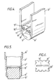
- Figures 4, 5 and 6 are related to a further embodiment of the glue dispenser (like items being numbered alike with a "′"). It is to be noted that the operation of this dispenser is the same as that previously described with reference to Figures 1, 2 and 3, and that variations are only related to the shape of the dispenser.
- the sphere 5 is replaced by a cylindrical member 5′, the cylindrical surface of which picks up and applies the adhesive to the surface as it is rolled over it.
- FIG 4 is a perspective view of a further embodiment of a glue dispenser.
- the shape of the seating 6′ of the neck portion 3′ is now cylindrical instead of spherical.
- the body and the protective cap (not shown) of the dispenser may be prismatic instead of cylindrical to accommodate the change in shape.
- the adhesive is dispensed using a cylindrical member instead of a sphere, wider strips of adhesive can be obtained than if a sphere is used.
- the tapering of the lower part and hence the seating 6′ of the neck portion 3′ is made to follow the geometry of the cylindrical member 5′, thereby retaining the member and allowing a layer of adhesive to be dispensed.
- the resilient component 8′ has the approximate shape of a rectangle, which has an inner aperture 11′ in the form of an elongated slot as shown in Figure 6.
- the elongate slot is as long as the cylindrical member 5′.
- square cut-outs 10′ are disposed around the periphery of the component 8.
- the cut-outs 10′ are not equispaced as before.
- the retaining function and the elastic properties of the component 8′ need to be similar to those shown for the component 8, shown in Figure 3, but allowing for the change in size and shape of the dispenser.
- the component 8 has a central aperture 11 which not only keeps the sphere 5 in its proper position but as it is circular in shape, it ensures that the sphere 5 will roll without being displaced out of its former position when subjected to an upward force when the dispenser is being used.
- the component can have a greater thickness and the aperture 11 can have its walls tapered to receive more suitably the surface of the sphere 5 which comes into contact with the component 8. This ensures that the sphere is maintained in its proper position.
- the walls defining the aperture 11′ may be shaped to match the curvature of the cylindrical surface of the cylindrical member 5′.
- the sphere 5 or cylindrical member 5′ is pressed on to the surface to be glued.
- the dispenser is then moved over the surface following the direction of the line where the glue is to be applied. This ensures that an adhesive layer of uniform width and constant thickness is applied as desired to all the surface to be glued.
- the associated resilient component 8 or 8′ will maintain a certain return pressure on the sphere 5 or cylindrical member 5′, thereby ensuring that a constant clearance is maintained between the lower ends and their respective seatings 6 and 6′ of the neck portions 3 and 3′, and the sphere or member. This clearance depends on the elastic properties of the components 8 and 8′, on the viscosity of the adhesive employed, and also on the pressure applied.
- the role of the sphere 5 or cylinder 5′ is not a flow controller for a gravity flow, as the liquid adhesive is not dispensed by capillary action. It has the function of obstructing the exit of a viscous or semi-paste adhesive from the dispenser, the mode of flow of the adhesive not being determined by capillary action.
- the sphere 5 or cylinder 5′ is not left free to vary its position according to the flow of the adhesive, since it is precisely located within a well defined limited range of positions that is, between the seating 6, 6′ and the resilient component 8, 8′.
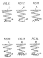
- FIGS 7 and 9 illustrate another embodiment of a resilient component which may be used in a dispenser having a sphere as the rotatable member.
- the operation of the dispenser incorporating such a component is identical to that described previously.
- the resilient component illustrated comprises a spirally wound spring 13 which is expanded into a frusto-conical shape and carries at one end a spherical concave cap 14 which engages the sphere 5.
- the end of the spring carrying the cap 14 is of smaller diameter than the other end of the spring which engages the detent 7 as previously described.
- Figures 10 and 11 illustrate further embodiments of the spring-cap arrangement shown in Figures 7 and 9.
- the spherical concave cap 14 is replaced by a ring 18 which is attached to the lower end of the spring 17, the spring 17 being similar to spring 13.
- the ring 18 is designed to be matched with the surface of the sphere 5. If the ring 18 is made of a wire which is too thick to provide adequate engagement between the ring 18 and the sphere 5, the inner surface of the ring can be shaped to produce the desired engagement with the sphere 5.
- a spring 15 similar to the spring 13 of Figures 7 and 9, carries at its lower end a claw 16.
- the claw 16 is shaped like a skeleton of the cap 14 and is made using segments of curved wire which form a structure to support the sphere 5.
- both the cap 14 and the claw 16 each have a radius of curvature which is substantially the same as the radius of curvature of the sphere 5 which they support.
- Figures 8 and 12 illustrate a resilient component for use in a dispenser having a cylinder as the rotatable member.
- a spirally wound spring 19 carries a cylindrical concave cap 20 at its lower end.
- Spring 19 is similar to spring 13 as described previously.
- the cylindrical cap 20 engages the cylindrical member 5′ and retains it within the lower end of the dispenser 4′ urging it against the seating 6′.
- the cylinder 5′ is pressed into the neck portion 3′ against the action of the spring 19.
- Figures 13 and 14 illustrate further embodiments of the spring-cap arrangement which can be used as the resilient component in a dispenser as illustrated in Figure 8.
- Figure 13 illustrates a support element 22 attached to the lower end of spring 21.
- the support element 22 is formed by a series of curved wire segments which are attached to a straight central wire.
- Figure 14 shows an element 24 which is formed from wire and which is designed in the shape of a saddle to engage the surface of cylindrical element 5′.
- the element 24 is attached to a spring 23.
- Springs 19, 21 and 23 are similar to spring 13, and naturally the radius of curvature of each of the parts designed to engage the cylindrical member 5′ is chosen to match that of the cylindrical member 5′ itself.
- the springs 19, 21 and 23 may have a circular cross section or, in order to improve the fit within the inner part of the neck portion 3′, may be slightly elliptical.
- the scope of the present invention includes the construction of larger size glue dispensers, preferably having a cylindrical member in the neck portion.
- a large adhesive reservoir is required instead of the small adhesive cylinder.
- the large reservoir can be connected by a duct to the dispenser, the dispenser being secured to a mechanical arm in an assembly line (e.g. an automatic cardboard containers assembly line).
- the adhesive may be kept in a large tank which has means for homogenizing and constant refilling are provided.
- the elastic characteristics of the resilient component 8′ will be chosen to allow continuous operation of the dispenser.
- composition of the resilient components must be chosen to be compatible with the adhesive to be dispensed.
- adhesive is not likely to attack the elastomeric material used, commonly known resilient rubbers may be used to form the resilient component 8, 8′.
- the resilient member 8, 8′ may be in the form of a highly elastic thin metal plate. This has the advantage of being resistant to chemical attack by most adhesive materials.
- the surface of the rotatable member 5, 5′ may have a surface texture which assists in the transfer of adhesive from the applicator 3, 3′ on to a surface on to which the adhesive is to be deposited.
Landscapes
- Coating Apparatus (AREA)
Applications Claiming Priority (2)
| Application Number | Priority Date | Filing Date | Title |
|---|---|---|---|
| BR8801000A BR8801000A (pt) | 1988-03-08 | 1988-03-08 | Aplicador de adesivo |
| BR8803432A BR8803432A (pt) | 1988-07-08 | 1988-07-08 | Aperfeicoamento em dispositivo aplicador de adesivo |
Publications (1)
| Publication Number | Publication Date |
|---|---|
| EP0331843A1 true EP0331843A1 (fr) | 1989-09-13 |
Family
ID=25664253
Family Applications (1)
| Application Number | Title | Priority Date | Filing Date |
|---|---|---|---|
| EP88311134A Withdrawn EP0331843A1 (fr) | 1988-03-08 | 1988-11-24 | Distributeur d'adhésif |
Country Status (3)
| Country | Link |
|---|---|
| EP (1) | EP0331843A1 (fr) |
| AU (1) | AU3346589A (fr) |
| WO (1) | WO1989008563A1 (fr) |
Cited By (7)
| Publication number | Priority date | Publication date | Assignee | Title |
|---|---|---|---|---|
| EP0685348A4 (fr) * | 1993-12-06 | 1996-04-24 | Mitsubishi Pencil Co | Stylo a bille. |
| WO1997015460A1 (fr) * | 1995-10-20 | 1997-05-01 | Kores Holding Zug Ag | Stylo pour appliquer des fluides de couleur ou de correction |
| EP1004457A1 (fr) * | 1998-11-24 | 2000-05-31 | Masaaki Fukami | Stylo à bille comprennant une valve d'encre à bille |
| WO2005027683A1 (fr) * | 2003-09-23 | 2005-03-31 | Antonio Silvio Sampaio Doria | Applicateur cylindrique pour distribuer des compositions cosmetiques |
| CN105620086A (zh) * | 2016-03-07 | 2016-06-01 | 于卫华 | 双层珠孔板万向旋珠笔 |
| CN105620085A (zh) * | 2016-03-03 | 2016-06-01 | 于卫华 | 抽吸油墨管万向轮盘笔 |
| US20220194119A1 (en) * | 2019-04-10 | 2022-06-23 | Societe Bic | Ball point tip and writing instrument fitted with such a ball point tip |
Families Citing this family (5)
| Publication number | Priority date | Publication date | Assignee | Title |
|---|---|---|---|---|
| US5676481A (en) * | 1991-09-26 | 1997-10-14 | Gillette Company | Marking instruments |
| GB9120517D0 (en) * | 1991-09-26 | 1991-11-06 | Gillette Co | Marking instruments |
| DE102014005453A1 (de) | 2014-04-12 | 2014-11-06 | Daimler Ag | Rollstift zum Auftragen von Klebstoff |
| CN114273149B (zh) * | 2021-12-25 | 2022-07-22 | 宁波内索尔工具有限公司 | 一种胶带生产用涂胶机、胶带生产线及生产工艺 |
| CN114833039B (zh) * | 2022-04-20 | 2023-04-28 | 上海师范大学 | 基于深度学习的时间-压力点胶系统胶体余量预测方法 |
Citations (13)
| Publication number | Priority date | Publication date | Assignee | Title |
|---|---|---|---|---|
| DE389452C (de) * | 1922-05-14 | 1924-02-06 | Voester & Mueller G M B H | Fluessigkeitsspender fuer Leim |
| FR612288A (fr) * | 1925-02-19 | 1926-10-20 | Perfectionnements aux dispositifs permettant d'appliquer des matières liquides ou semi-liquides sur papier ou autres corps pour les humidifier, les colorer, les gommer,les teindre ou autres usages | |
| US2444003A (en) * | 1945-01-19 | 1948-06-22 | Eagle Pencil Co | Writing implement |
| DE812049C (de) * | 1949-02-08 | 1951-08-27 | Heinz Pickhardt | Verschluss fuer Leimflaschen |
| FR1071169A (fr) * | 1951-10-27 | 1954-08-26 | Distributeur d'adhésif | |
| DE958995C (de) * | 1952-12-06 | 1957-02-28 | Hermann Halfmann | Fluessigkeitsspender, insbesondere Leimspender, in Taschenformat |
| FR1137013A (fr) * | 1955-11-21 | 1957-05-22 | Dispositif pour la distribution d'une matière pâteuse telle que de la colle | |
| US2975466A (en) * | 1957-05-13 | 1961-03-21 | Owens Illinois Glass Co | Ball-type liquid applicators |
| US3048881A (en) * | 1958-10-03 | 1962-08-14 | Dolletta M Ackerman | Liquid dispenser and applicator |
| US3100908A (en) * | 1961-04-03 | 1963-08-20 | Engle Paul | Container cover with a roller applicator |
| DE3044223C1 (de) * | 1980-11-25 | 1981-12-24 | Hans-Jörg 6251 Selters Simon | Verpackungs- und Applikationseinheit fuer schnellhaertende Klebstoffe u.ae. Materialien |
| US4342522A (en) * | 1977-03-10 | 1982-08-03 | Bristol-Myers Company | Roll-on dispenser with a flexible membrane |
| EP0210312A1 (fr) * | 1985-06-26 | 1987-02-04 | Pilot Man-Nen-Hitsu Kabushiki Kaisha | Stylo à bille pour encre aqueuse |
-
1988
- 1988-11-24 EP EP88311134A patent/EP0331843A1/fr not_active Withdrawn
-
1989
- 1989-03-07 WO PCT/BR1989/000005 patent/WO1989008563A1/fr not_active Ceased
- 1989-03-07 AU AU33465/89A patent/AU3346589A/en not_active Abandoned
Patent Citations (13)
| Publication number | Priority date | Publication date | Assignee | Title |
|---|---|---|---|---|
| DE389452C (de) * | 1922-05-14 | 1924-02-06 | Voester & Mueller G M B H | Fluessigkeitsspender fuer Leim |
| FR612288A (fr) * | 1925-02-19 | 1926-10-20 | Perfectionnements aux dispositifs permettant d'appliquer des matières liquides ou semi-liquides sur papier ou autres corps pour les humidifier, les colorer, les gommer,les teindre ou autres usages | |
| US2444003A (en) * | 1945-01-19 | 1948-06-22 | Eagle Pencil Co | Writing implement |
| DE812049C (de) * | 1949-02-08 | 1951-08-27 | Heinz Pickhardt | Verschluss fuer Leimflaschen |
| FR1071169A (fr) * | 1951-10-27 | 1954-08-26 | Distributeur d'adhésif | |
| DE958995C (de) * | 1952-12-06 | 1957-02-28 | Hermann Halfmann | Fluessigkeitsspender, insbesondere Leimspender, in Taschenformat |
| FR1137013A (fr) * | 1955-11-21 | 1957-05-22 | Dispositif pour la distribution d'une matière pâteuse telle que de la colle | |
| US2975466A (en) * | 1957-05-13 | 1961-03-21 | Owens Illinois Glass Co | Ball-type liquid applicators |
| US3048881A (en) * | 1958-10-03 | 1962-08-14 | Dolletta M Ackerman | Liquid dispenser and applicator |
| US3100908A (en) * | 1961-04-03 | 1963-08-20 | Engle Paul | Container cover with a roller applicator |
| US4342522A (en) * | 1977-03-10 | 1982-08-03 | Bristol-Myers Company | Roll-on dispenser with a flexible membrane |
| DE3044223C1 (de) * | 1980-11-25 | 1981-12-24 | Hans-Jörg 6251 Selters Simon | Verpackungs- und Applikationseinheit fuer schnellhaertende Klebstoffe u.ae. Materialien |
| EP0210312A1 (fr) * | 1985-06-26 | 1987-02-04 | Pilot Man-Nen-Hitsu Kabushiki Kaisha | Stylo à bille pour encre aqueuse |
Cited By (10)
| Publication number | Priority date | Publication date | Assignee | Title |
|---|---|---|---|---|
| EP0685348A4 (fr) * | 1993-12-06 | 1996-04-24 | Mitsubishi Pencil Co | Stylo a bille. |
| US5711626A (en) * | 1993-12-06 | 1998-01-27 | Mitsubishi Pencil Kabushiki Kaisha | Ball-point pen with back flow stop |
| WO1997015460A1 (fr) * | 1995-10-20 | 1997-05-01 | Kores Holding Zug Ag | Stylo pour appliquer des fluides de couleur ou de correction |
| US5971648A (en) * | 1995-10-20 | 1999-10-26 | Kores Holding Zug Ag | Pen for applying a color or correction liquid |
| EP1004457A1 (fr) * | 1998-11-24 | 2000-05-31 | Masaaki Fukami | Stylo à bille comprennant une valve d'encre à bille |
| WO2005027683A1 (fr) * | 2003-09-23 | 2005-03-31 | Antonio Silvio Sampaio Doria | Applicateur cylindrique pour distribuer des compositions cosmetiques |
| CN105620085A (zh) * | 2016-03-03 | 2016-06-01 | 于卫华 | 抽吸油墨管万向轮盘笔 |
| CN105620086A (zh) * | 2016-03-07 | 2016-06-01 | 于卫华 | 双层珠孔板万向旋珠笔 |
| US20220194119A1 (en) * | 2019-04-10 | 2022-06-23 | Societe Bic | Ball point tip and writing instrument fitted with such a ball point tip |
| US12220938B2 (en) * | 2019-04-10 | 2025-02-11 | SOCIéTé BIC | Ball point tip and writing instrument fitted with such a ball point tip |
Also Published As
| Publication number | Publication date |
|---|---|
| WO1989008563A1 (fr) | 1989-09-21 |
| AU3346589A (en) | 1989-10-05 |
Similar Documents
| Publication | Publication Date | Title |
|---|---|---|
| US4940350A (en) | Fluid ball applicator with vent tube | |
| US6227737B1 (en) | Fluid applicators | |
| EP1557289A1 (fr) | conteneur pour distribution de liquide pour instrument de marquage | |
| US4180160A (en) | Wet tissue container | |
| EP0016141B1 (fr) | Appareil d'alimentation en liquide d'un dispositif applicateur | |
| WO1989008563A1 (fr) | Distributeur d'adhesif | |
| EP0111875B1 (fr) | Pulvérisateur à distribution dosée | |
| US5526960A (en) | Perfume dispenser with replaceable cartridges | |
| US4848947A (en) | Liquid applicator device with tilt valve | |
| US6309128B1 (en) | Applicator device | |
| US4029422A (en) | Dispenser for air drying liquid coating | |
| WO1996018571A1 (fr) | Applicateur de parfum a cartouche jetable | |
| GB2195585A (en) | Roll-on dispensing package | |
| JPS6382970A (ja) | ペースト状又は粉末状の製品用の塗布ユニット | |
| JP2003144223A (ja) | 化粧製品などの製品の収容及び分配のための装置 | |
| US4035090A (en) | Applicator | |
| EP2825393A1 (fr) | Applicateur de liquide de précision | |
| EP0869873B1 (fr) | Applicateurs de fluide | |
| US7841793B2 (en) | Device for packaging and applying a cosmetic product | |
| WO1998051587A1 (fr) | Ensemble distributeur-applicateur | |
| KR102310169B1 (ko) | 틸트 작용 펌프 | |
| US2316040A (en) | Fountain-type marking device | |
| US2252542A (en) | Adhesive dispenser | |
| US2932277A (en) | Moistening device | |
| US4917521A (en) | Pen type container for correction fluid with daubing function |
Legal Events
| Date | Code | Title | Description |
|---|---|---|---|
| PUAI | Public reference made under article 153(3) epc to a published international application that has entered the european phase |
Free format text: ORIGINAL CODE: 0009012 |
|
| AK | Designated contracting states |
Kind code of ref document: A1 Designated state(s): AT BE CH DE ES FR GB GR IT LI LU NL SE |
|
| STAA | Information on the status of an ep patent application or granted ep patent |
Free format text: STATUS: THE APPLICATION IS DEEMED TO BE WITHDRAWN |
|
| 18D | Application deemed to be withdrawn |
Effective date: 19900314 |