EP0331896A2 - Dispositif pour introduire, stocker et distribuer des objets et articles en forme de feuille emmagasinés dans des cassettes - Google Patents
Dispositif pour introduire, stocker et distribuer des objets et articles en forme de feuille emmagasinés dans des cassettes Download PDFInfo
- Publication number
- EP0331896A2 EP0331896A2 EP89101531A EP89101531A EP0331896A2 EP 0331896 A2 EP0331896 A2 EP 0331896A2 EP 89101531 A EP89101531 A EP 89101531A EP 89101531 A EP89101531 A EP 89101531A EP 0331896 A2 EP0331896 A2 EP 0331896A2
- Authority
- EP
- European Patent Office
- Prior art keywords
- organ
- cassette
- cassettes
- conveyor
- opening
- Prior art date
- Legal status (The legal status is an assumption and is not a legal conclusion. Google has not performed a legal analysis and makes no representation as to the accuracy of the status listed.)
- Ceased
Links
- 210000000056 organ Anatomy 0.000 claims abstract description 50
- 239000000463 material Substances 0.000 claims description 10
- 210000003127 knee Anatomy 0.000 claims description 8
- 230000007246 mechanism Effects 0.000 claims description 8
- 210000002414 leg Anatomy 0.000 claims description 7
- 125000006850 spacer group Chemical group 0.000 description 6
- 238000010586 diagram Methods 0.000 description 5
- 238000006073 displacement reaction Methods 0.000 description 4
- 230000008901 benefit Effects 0.000 description 3
- 230000001934 delay Effects 0.000 description 2
- 230000002093 peripheral effect Effects 0.000 description 2
- 229920004943 Delrin® Polymers 0.000 description 1
- 240000000731 Fagus sylvatica Species 0.000 description 1
- 235000010099 Fagus sylvatica Nutrition 0.000 description 1
- 230000005540 biological transmission Effects 0.000 description 1
- 230000036461 convulsion Effects 0.000 description 1
- 230000008878 coupling Effects 0.000 description 1
- 238000010168 coupling process Methods 0.000 description 1
- 238000005859 coupling reaction Methods 0.000 description 1
- 230000003111 delayed effect Effects 0.000 description 1
- 230000007613 environmental effect Effects 0.000 description 1
- 230000006870 function Effects 0.000 description 1
- 238000000034 method Methods 0.000 description 1
- 230000008569 process Effects 0.000 description 1
- IHQKEDIOMGYHEB-UHFFFAOYSA-M sodium dimethylarsinate Chemical class [Na+].C[As](C)([O-])=O IHQKEDIOMGYHEB-UHFFFAOYSA-M 0.000 description 1
Images

Classifications
-
- G—PHYSICS
- G07—CHECKING-DEVICES
- G07D—HANDLING OF COINS OR VALUABLE PAPERS, e.g. TESTING, SORTING BY DENOMINATIONS, COUNTING, DISPENSING, CHANGING OR DEPOSITING
- G07D11/00—Devices accepting coins; Devices accepting, dispensing, sorting or counting valuable papers
- G07D11/009—Depositing devices
- G07D11/0096—Accepting paper currency or other valuables in containers, e.g. in code-marked envelopes
-
- G—PHYSICS
- G07—CHECKING-DEVICES
- G07D—HANDLING OF COINS OR VALUABLE PAPERS, e.g. TESTING, SORTING BY DENOMINATIONS, COUNTING, DISPENSING, CHANGING OR DEPOSITING
- G07D11/00—Devices accepting coins; Devices accepting, dispensing, sorting or counting valuable papers
- G07D11/10—Mechanical details
- G07D11/14—Inlet or outlet ports
Definitions
- the invention relates to a device for inputting, storing and dispensing objects to be stored in cassettes and sheet-like material according to the preamble of patent claim 1.
- a device for entering, storing and dispensing objects to be stored in cassettes and of sheet-like goods is indicated wherever sheet-like goods, as well as small non-sheet-shaped parts, or entire bundles of sheet-like goods are to be protected from violent access or environmental influences.
- a device of this type is described in EP-A 0182 137. It is a cash vault which is at cash desks of financial institutions, e.g. B. banks are used and designed so that larger amounts from an armored vault can only be delayed by funding.
- the well-known cash vault has z. B. the local currency and cassettes, in the z. B. bundles of banknotes of other currencies, coins, jewelry and the like can be stowed, two separate openings.
- the cash register can be placed between two cash counters. Each cashier can use his terminal to control only the storage units and storage spaces assigned to him.
- the invention has for its object to provide a device that allows objects to be stored in cassettes and sheet-like material Space-saving and quickly secured to stow away and cassettes and sheet-like goods to go out in one place.
- the cassette is held self-locking or in the immediate vicinity of a dead center both when it is received by a conveyor and in the delivery position in a mechanical dead center of the swivel mechanism of a swiveling member.
- This position of the dead centers results in a smooth and in no way jerky start-up of the pivotable member of the device.
- the cassette, which originates from different conveyors, and the sheet-like material can be made exactly one opening by means of the pivotable member. Thanks to this exact positioning, the opening can be made with minimal dimensions. This small opening is significantly more secure against external interference and can also be closed more effectively against the use of force than a large opening.
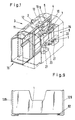
- the device for entering, storing and dispensing objects that can be stored in cassettes 1 and sheet-shaped goods 2 is designed as a cash vault 3, which is shown in FIG. 1 with a partial section through its vault interior 4 and its armor 5.
- cassettes 1 with e.g. Hard money, banknotes individually or in bundles of foreign currencies, special coins, jewelery or securities, and 10 banknotes 2 stored on several rolls of a roll storage device as sheet-shaped goods separated according to currency and values.
- the roll storage device 10 can be designed in accordance with the storage device described in the European patent application 88103427.6 which does not belong to the prior art.
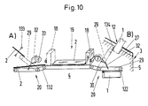
- the cash vault 3 is usually set up between two cash counters and is operated jointly by two cashiers A, B, as indicated in FIG. 10.
- Each cashier has on his side a terminal 11 for data input for a control device (not shown) in the safe door 16 for the cash safe 3, and an input and output opening 12 for the objects stored in the cassettes 1 and the bank notes 2.
- the input of the bank notes 2 takes place for both cashiers jointly through an input opening 13 in the middle of the surface of the cash safe 3.
- the banknotes 2 inserted into the opening 13 are separated by a separating mechanism, not shown, by means of a testing device (not shown) (in particular for sticking together, possibly also for authenticity) checked, and stored on a conveyor 15 in the roll memory 10.
- the cassettes 1 are in the cassette memory 9.
- the input, storage and output are controlled by the control device, the terminal 11 of which can be seen in FIG. 1 on the top of the cash safe 3, and also the composition of the bank notes 2 Nem banknote bundle 2, starting from the roll store 10.
- the banknote or banknotes 2 are fetched from the roll store 10 by the conveyor 15 and stored in a collecting box 19. From this collecting box 19, the bundle 2, as shown schematically in FIG. 10, depending on which cashier A or B it is intended for, is pushed with a conveyor designed as a slide 18 to a right or left device 20 in the safe interior 4.
- the device 20 takes over the bundle of banknotes 2 and pushes it through the right or left opening 12 for removal by the cashier in question.
- the cassette storage 9 has two internal storage spaces 21 for the cassettes 1, a horizontal transverse displacement device 22 and a lift 23 for vertical transport.
- a cassette 1 selected by the control device is pushed over the transverse shifting device 22 from its place in one of the two storage spaces 21 to the lift 23, lifted by this to the device 20 and, as described below, taken over by the latter and then transported through the opening 12, where its content is removed by the cashier B.
- the cassette 1 is either z. B. filled with banknotes 2, or bundles, hard money, etc., or withdrawn empty through the opening 12 and returned to their original place in one of the storage spaces 21.
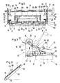
- the device 20 used for dispensing bundles of banknotes 2 and for receiving and moving the cassette 1; is shown in a plan view in Fig. 2 and in a side layer in Fig. 3 and 4 respectively.
- the device 20 is fastened with a right and left flange 25 and 26 to a support 8 (FIG. 1) which can be pulled out of the safe interior 4.
- the bundle of banknotes 2 and the cassette 1 can be guided through the opening 12, which is kept small for security reasons, and lie there within easy reach for the cashier, the bundle of banknotes 2 and the cassettes 1 are inserted via a pivotable plate-shaped member 29 direction 20 brought directly under the opening 12, and then pushed through it.
- the opening 12 is only open during dispensing. The rest of the time it is closed with a slide 27.
- the pivoting of the organ 29 takes place about a pivot axis 30 by means of two cranks 31 and two angle levers 32, the two cranks 31 being fastened in a rotationally fixed manner to a drive shaft 33.
- the axis 33 is rotated by a motor 35 attached to the flange 26. As shown in Fig.
- the drive shaft 33 is above and parallel to the pivot axis 30, and is supported by a bearing 37 and 39 in the flanges 25 and 26 of the device 20.
- the axis 33 and the motor 35 are connected to one another via a coupling 40.
- Each of the other two angle levers 32 is pivotally mounted at the end of the crank 31 and approximately in the middle of an upwardly bent outer side edge 41 or 42 of the member 29 by bolts 43 and 44 pressed into it.
- the bolts 43 and 44 are secured by snap rings from slipping out of a bore 47 in the crank 31 or the edges 41 and 42.
- the pivot axis 30 is horizontal, and is also rotatably held on each of the flanges 25 and 26 by a bearing 45 and 46, respectively.
- the organ 29 is pivotally supported on the axis 30 by a bearing 49 and 50 in the rearward extension of its edges 41 and 42.
- the pivot axis 30 is thus freely rotatable in the flanges 25 and 26, and also the member 29 freely rotatable on the pivot axis 30.
- the bearings 45 and 49, and 46 and 50 are each spaced apart by a spacer bushing 51 and 52. The spacers 51 and 52 distance and position the member 29 laterally to the two flanges 25 and 26.
- the cranks 31 have the bore 47 at one end and a bore 48 at the other.
- the bore 47 receives the bolt 43 and the drive shaft 33 is inserted in the bore 48.
- an outlet is located in the surface a notch towards the bore 48, but radially limited to the outside.
- a pin 54 inserted through the drive shaft 33, as indicated in FIGS. 3 and 4.
- the pin 54 serves to transmit power from the drive shaft 33 to the crank 31.
- the movement of the pin 54 out of the notch of the crank 31 is achieved by a snap ring seated in a groove in the drive shaft 33 55 prevents that pushes against the crank 31; the radial closure of the notch prevents the pin 54 from slipping out radially.
- Each angle lever 32 has an upwardly directed knee 56 approximately in its center, the knee legs forming an angle of approximately one hundred and thirty degrees in the hollow of the knee.
- One knee leg is, as described above, rotatable on the crank 31 with a bolt 43, and the other is rotatable about a further bolt 44 and secured with a snap ring, approximately in the middle of the edge 41 or 42 of the organ 29.
- a leg 57 extends from the end of the angle lever 32, which is mounted in the organ 29 with the bolt 44, at approximately a right angle in the direction of the knee 56.
- toothed belt wheels 60, 61, 62 and 63 which are non-rotatably pinned to the pivot axis 30.
- the pinning takes place analogously to the crank 31 on the drive shaft 33.
- the toothed belt wheels 60 to 63 are driven by a motor 65 via the pivot axis 30.
- an axis 70 and 71 On the two edges of the side of the organ 29 opposite the pivot axis 30, there are, each held by two bearing blocks, an axis 70 and 71, each with two toothed belt wheels 72 and 73.
- the toothed belt wheels 60, 61 and 62, 63 and the toothed belt wheels 72 and 73 are connected by two pairs of toothed belts 66 and 67, respectively.
- the four toothed belts 66 run over the top 75 of the organ 29 and back again via the bottom 76.
- a slide 77 is clamped at its outer edges to one of the pairs of toothed belts 66 and 67 in such a way that it can be displaced parallel to the swivel axis 30 via the underside 76.
- About an eighty percent of the width of the slide 77 extends on the side facing the pivot axis 30 symmetrically to the center of the side, an angled extension 79, which serves to push the cassette 1 through the opening 12.
- An angled gripper 81 is located at the same height as the extension 79 on the outer edges of the slide 77. In each of the Gripper 81 grips an eyelet 82 on the lower outer edge of the cassette 1, as shown in FIG. 9, for retracting the cassette 1.
- An internally hollow shaft 84 is pushed over the pivot axis 30. On each side of the shaft 84 there is a spacer 85 or 87 on the swivel axis 30. In its position, the shaft 84 is fixed by a snap ring 90 in a groove in the swivel axis 30 on the side facing the toothed belt wheel 62 and on the opposite side the spacer 85 abuts the toothed belt wheel 61 directly.
- the shaft 84 has a toothed belt wheel 91 and a toothed wheel 92 on the side adjoining the spacer disk 85 and then a spacer beech 93 and a toothed belt wheel 94 alternately in three times.
- the three toothed belt wheels 94 are approximately symmetrical to the center of the organ 29.
- Three toothed belts 101 run over them on the top and bottom sides 75 and 76.
- the toothed belts 101 are supported by three toothed belt wheels 102 on a shaft 99 redirected.
- a hold-down device 103 is located above the top 75.
- the hold-down device 103 has a bracket 104, a shaft 105 parallel to the swivel axis 30 with a toothed belt wheel 100 pinned analogously to crank 31, and three elastic transport rollers 109 which, in the swiveling process described below, act directly on the toothed belt 101 come to lie, and a spring plate 110.
- the spring plate 110 is welded to the side of the bracket 104 pointing away from the pivot axis 30.
- the bracket 104 is screwed to two rails 111 approximately in the middle.
- the rails 111 are each pivotably supported by means of a bearing 112 on an axis 113 which is rigidly connected to the edges 41 and 42 at the same height as the pivot axis 30 and parallel to it.
- the shaft 105 is held in a respective bearing 115.
- the toothed belt wheel 100 is located next to one of the rails 111 within the hold-down device 103.
- the bracket 104 forms an angle of approximately thirty degrees with each rail 111, the angle apex pointing to the shaft 105.
- a toothed belt wheel 97 and a toothed wheel 96 run on the axis 113, through one of the rails 111 on one end face and through one on the other side Clamping ring 117 are prevented from migrating sideways.
- the gear 92 on the shaft 84 drives the gear 96 and the toothed belt wheel 97 directly.
- a toothed belt 119 runs to the toothed belt wheel 100 via the toothed belt wheel 97.
- the transmission via the toothed wheels 92, 96, the toothed belt wheel 97, the toothed belt 119 and the toothed belt wheel 100 to the transport rollers 109 serves to transport the transport rollers 109 at the same peripheral speed as the toothed belt 101 to let go.
- a tension spring 120 is arranged at a distance of a few millimeters from the rail 111, which pulls the hold-down device 103 toward the member 29. Also attached to the upper edge of the bracket 104 is a plastic band 121 which, when the organ 29 is in a horizontal position, distances the hold-down device 103 from the organ 29 a few millimeters against the force of the two springs 120, as shown in FIG. 3.
- the two rail guides 122 are mirror images of one another. They are shaped in such a way that they each have an attachment 123 on their part lying on the underside 76 of the organ 29, the two attachments pointing towards one another parallel to the organ 29. Each of the rail guides 122 is pulled by a spring 125 to the relevant edge 41, 42. At the upper edge of the rail guide 122, an extension 129 points away from the organ 29. Also on the upper edge of the rail guide 122, a pin-shaped extension 130 is formed as an axis in the longitudinal direction thereof, which is inserted in a plastic bearing block 131, preferably made of Delrin.
- the plastic blocks 131 are screwed to the edges 41 and 42.
- the bolt 44 of the angle lever 32 in the edges 41 and 42 extends through an opening in each of the rail guides 122. A pivoting movement of each rail guide 122 is thus not hindered by the bolts 44.
- the cassettes 1 are an internally hollow rectangular parallelepiped that is open on one of its long sides. As shown in FIG. 9, one of the eyelets 82 is formed on the side opposite the open long side in the vicinity of the edge to the broad sides and in the immediate vicinity of one of the cover surfaces. A projection 127 runs along each of the eyelets 82 along the respective side surface. As shown in FIGS. 6 and 7, the cassette 1 is held by the projection 123 of the rail guide 122 at its projection 127, gripped or slides on it, as described further below.
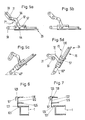
- the pivotable member 29 To receive the bundle of banknotes 2 from the collecting box 19, the pivotable member 29 is in a horizontal position, as shown in FIGS. 5b and 10. In the horizontal position, the pivot point with the bolt 43 of the angle lever 32 and the crank 31 lies slightly above the connecting line between the center of the drive shaft 33 and the center of the bolt 44, ie the pivot mechanism with the crank 31 and the angle lever 32 has not yet reached its bottom dead center reached.
- the hold-down device 103 is lifted off the organ 29 by the plastic band 121, so that the bundle of banknotes 2 pushed by the slide 18 out of the collecting box 19 onto the top 75 of the organ 29 is not hindered.
- a toothed belt 132 is connected to the conveyor 18 via a slip clutch, not shown, and drives the axle 84 via the toothed belt wheel 91.
- the axis 84 drives the toothed belts 101 via the three toothed belt wheels 94, and the toothed wheel 96 with the toothed belt wheel 97 and the axis 113 via the toothed wheel 92.
- the conveying speed of the banknote bundle 2 coincides with the speed of the toothed belt 101 and the peripheral speed of the three elastic rollers 109. If about twenty percent of the banknote length has passed under the transport rollers 109, the movement is stopped.
- the member 29 is pivoted upward about the pivot axis 30 to the axis 33.
- the hold-down device 103 touches with its spring plate 110 the banknote bundle 2 lying on the organ 29.
- the transport rollers 109 also press onto the banknote bundle 2.
- the banknote bundle 2 is now firmly clamped in place and pivoting continues to an angle of forty degrees from the horizontal as shown in FIG. 5c until the bundle of banknotes 2 is directly under the opening 12.
- the drive via the toothed belt 132 is started again and the bundle of banknotes 2 is pushed through the opening 12 until it is just the Has passed transport rollers 109, but is still held properly by the spring plate 110 of the hold-down device 103.
- the banknote bundle 2 now protrudes from the opening 12 in a good gripping position for the cashier and can be removed.
- the organ 29 is held in this inclined position only by the force of the motor 35. This is possible because the weight of the bundle of banknotes 2 is low and no forces are exerted on the organ 29 through the opening 12.
- the removal of the banknote bundle 2 is determined by an electro-optical sensor 133 in the opening 12. After removal, the organ 29 is pivoted back into the horizontal position, as shown in Fig. 5b.
- the device 20 is ready to receive bundles of banknotes 2 again.
- the crank 31 is rotated downward by about seven degrees beyond the position shown in FIG. 5b into the position shown in FIG. 5a.
- the organ 29 is still in a horizontal position since the rotation takes place around the bottom dead center.
- the pivot point with the bolt 43 of the angle lever 32 and the crank 31 lies slightly, as shown in FIG. 5a, below the connecting line between the center of the drive shaft 33 and the center of the bolt 44, ie the pivot mechanism with crank 31 and angle lever 32 has just passed bottom dead center.
- the leg 57 has been moved with its free end by the additional rotation upward and pushes the shoulder 129 upward with its end.
- the rail guide 122 is pivoted about its axis, formed from the extensions 130 which are mounted in the blocks 131, ie the shoulder 123 is pressed outwards, as shown in FIG. 6.
- the slide 77 on the underside 76 of the organ 29 is in a position near the pivot axis 30.
- the cassette 1 selected by the control device is pushed by the transverse displacement device 22 to the lift 23, and is lifted by the latter under the organ 29.
- each of the cassettes 1 has two eyes 82 near its outer lower edge. These two eyes 82 snap into the grippers 81 of the slide 77.
- the motor 35 rotates both cranks 31 upwards, the leg 57 leaves the extension 130.
- Each of the rail guides 122 is, as in Fig. 6 ge shows, pulled by the spring 125 against the edge 41 or 42, whereby the cassette 1 is held with its lateral projection 127 by the extension 123 of the rail guide 122 on the member 29. Since this rotation takes place immediately around the bottom dead center of the pivot mechanism, the organ 29 has not carried out any pivot so far. A swivel now begins slowly and the motor 35 continues to rotate until the top dead center is exceeded when the organ 29 is inclined by approximately sixty degrees to the horizontal, and the hollow of the knee 56 of the angle lever 32 on the drive shaft 33, as shown in FIG. 5d, lies. In this position, the cassette 1 is located under the opening 12.
- the opening 12 is opened by the slide 27 and the cassette 1 sliding on the rail guide 122 through the grippers 81 and the attachment 79 on the slide 77 from the motor 65 via the shaft 30, the toothed belt wheels 60 to 63 and the toothed belt 119 shifted.
- Below the opening 12 there are further rails 134 in the opening 12, in which the projection 127 of the cassette 1 slides further as soon as it protrudes beyond the rail guides 122.
- the displacement of the slide 77 is stopped as soon as the cassette 1 comes close to the upper edge of the organ 29.
- the cassette 1 is now beyond the opening 12 and its content is removed by the cashier.
- the same cassette 1 is refilled or empty, it cannot be removed, is pulled back again, the slide 27 is closed, and the member 29 is pivoted back into the horizontal position shown in FIG. 5a, the rail guides 122 being opened again.
- the lift 23 takes over the cassette 1 in order to place it in the storage space 21 of the storage 5 via the transverse displacement device 22.
- the pivotable member 29 and the cassette storage 9 are designed so that cassettes 1 can be used with a single and double fill level.
- the slightly raised hold-down device 103 when inserting the banknote bundle 2 from the collecting box 19 onto the upper side 75 of the organ 29 has also proven itself; with appropriate dimensioning of the diameter of the transport rollers 109 and the force of the spring 120, however, the lifting could be dispensed with.
- belts with an adapted width can also be used with a slight structural adjustment.
Landscapes
- Physics & Mathematics (AREA)
- General Physics & Mathematics (AREA)
- Pile Receivers (AREA)
- Sheets, Magazines, And Separation Thereof (AREA)
- Delivering By Means Of Belts And Rollers (AREA)
Applications Claiming Priority (2)
| Application Number | Priority Date | Filing Date | Title |
|---|---|---|---|
| CH911/88A CH674396A5 (fr) | 1988-03-10 | 1988-03-10 | |
| CH911/88 | 1988-03-10 |
Publications (2)
| Publication Number | Publication Date |
|---|---|
| EP0331896A2 true EP0331896A2 (fr) | 1989-09-13 |
| EP0331896A3 EP0331896A3 (fr) | 1989-12-27 |
Family
ID=4198040
Family Applications (1)
| Application Number | Title | Priority Date | Filing Date |
|---|---|---|---|
| EP89101531A Ceased EP0331896A3 (fr) | 1988-03-10 | 1989-01-30 | Dispositif pour introduire, stocker et distribuer des objets et articles en forme de feuille emmagasinés dans des cassettes |
Country Status (4)
| Country | Link |
|---|---|
| US (1) | US5016546A (fr) |
| EP (1) | EP0331896A3 (fr) |
| JP (1) | JPH01267791A (fr) |
| CH (1) | CH674396A5 (fr) |
Families Citing this family (12)
| Publication number | Priority date | Publication date | Assignee | Title |
|---|---|---|---|---|
| IT1256495B (it) * | 1992-12-30 | 1995-12-07 | Giuseppe Ezio Fumanelli | Procedimento e dispositivo per la ricezione e l'erogazione automatizzata di banconote e valori |
| DE9314341U1 (de) * | 1993-09-23 | 1993-11-04 | Ascom Autelca AG, Gümligen, Bern | Kassentresor mit einer wahlweisen von zwei Kassierern zu bedienenden Tresorbedieneinheit |
| US5722332A (en) * | 1995-12-28 | 1998-03-03 | M.I.B. Elettronica S.R.L. | Apparatus and process for conducting deposit and drawing operations of banknotes and valuables |
| US5938072A (en) * | 1997-09-16 | 1999-08-17 | Magner Corporation | Rolled coin dispenser |
| US6293867B1 (en) | 1998-03-11 | 2001-09-25 | Bally Gaming, Inc. | Gaming machine payout system and method |
| US6014594A (en) * | 1998-03-11 | 2000-01-11 | Bally Gaming, Inc. | Gaming machine payout dispensing system with on escrow area and locks |
| US6332099B1 (en) | 1998-03-11 | 2001-12-18 | Bally Gaming, Inc. | Gaming machine payout controlling system and method |
| EP1188141A4 (fr) | 1999-04-23 | 2005-05-11 | Alliance Gaming Corp | Systeme et procede pour controler de maniere sure le stockage et la distribution d'un paiement |
| US20030014667A1 (en) * | 2001-07-16 | 2003-01-16 | Andrei Kolichtchak | Buffer overflow attack detection and suppression |
| KR101094627B1 (ko) * | 2005-01-04 | 2011-12-15 | 엘지엔시스(주) | 매체자동지급기의 접객장치 |
| US9865118B2 (en) * | 2012-07-31 | 2018-01-09 | Ncr Corporation | Cassette replenishment |
| US10957445B2 (en) | 2017-10-05 | 2021-03-23 | Hill-Rom Services, Inc. | Caregiver and staff information system |
Family Cites Families (17)
| Publication number | Priority date | Publication date | Assignee | Title |
|---|---|---|---|---|
| US1506491A (en) * | 1922-05-12 | 1924-08-26 | kline | |
| US2770516A (en) * | 1953-05-11 | 1956-11-13 | Mosler Safe Co | Depositing machines |
| US2963333A (en) * | 1957-01-14 | 1960-12-06 | Mestre Luis | Depositing machine |
| US3078789A (en) * | 1960-03-02 | 1963-02-26 | Bernard F Mcgee | Depositories |
| GB1302819A (fr) * | 1970-07-17 | 1973-01-10 | ||
| US3683826A (en) * | 1970-11-13 | 1972-08-15 | Shaw Walker Co | Drawer depository |
| US3836980A (en) * | 1973-05-03 | 1974-09-17 | Diebold Inc | Remote depository construction |
| US4164179A (en) * | 1974-10-21 | 1979-08-14 | Docutel Corporation | Depository System |
| DE2805252A1 (de) * | 1978-02-08 | 1979-08-09 | Hauni Werke Koerber & Co Kg | Schrankeinheit zum aufnehmen von banknoten |
| US4308804A (en) * | 1979-11-08 | 1982-01-05 | Honeywell Information Systems Inc. | Automatic cash depository |
| JPS57130189A (en) * | 1981-02-02 | 1982-08-12 | Laurel Bank Machine Co | Paper money storage box with reject pool section for paper money clearing machine |
| US4483255A (en) * | 1982-09-30 | 1984-11-20 | Collier Safe Co., Inc. | Night depository |
| GB2131082A (en) * | 1982-11-19 | 1984-06-13 | De La Rue Syst | Secure containers |
| GB2156904B (en) * | 1984-03-31 | 1987-05-07 | Burroughs Corp | Autoteller including tilt sensitive |
| DE3412424C1 (de) * | 1984-04-03 | 1985-06-27 | Nixdorf Computer Ag, 4790 Paderborn | Behaelter zur Aufnahme von Wertscheinen |
| US4726474A (en) * | 1984-05-08 | 1988-02-23 | Laurel Bank Machines Co., Ltd. | Circulating-type bill depositing and disbursing machine |
| ATE50373T1 (de) * | 1984-11-05 | 1990-02-15 | Ascom Autelca Ag | Kassentresor. |
-
1988
- 1988-03-10 CH CH911/88A patent/CH674396A5/de not_active IP Right Cessation
-
1989
- 1989-01-30 EP EP89101531A patent/EP0331896A3/fr not_active Ceased
- 1989-02-17 US US07/311,734 patent/US5016546A/en not_active Expired - Fee Related
- 1989-03-09 JP JP1055276A patent/JPH01267791A/ja active Pending
Also Published As
| Publication number | Publication date |
|---|---|
| JPH01267791A (ja) | 1989-10-25 |
| EP0331896A3 (fr) | 1989-12-27 |
| US5016546A (en) | 1991-05-21 |
| CH674396A5 (fr) | 1990-05-31 |
Similar Documents
| Publication | Publication Date | Title |
|---|---|---|
| DE3303809C2 (de) | Tragvorrichtung für in einem Banknotenbehälter gestapelte Banknoten | |
| DE2949344C2 (de) | Sicherheitskassette für die Verwendung in Geldscheinautomaten | |
| DE3516384C2 (fr) | ||
| DE69610366T2 (de) | Notenstapler | |
| EP0182137B1 (fr) | Coffre-fort pour comptoir-caisse | |
| DE2506195A1 (de) | Banknotenausgabegeraet | |
| DE69510586T2 (de) | Transaktionseinrichtung mit Teile zum Speichern von Blättern | |
| DE68902578T2 (de) | Pneumatische bargeld-foerderanlagen und buechsen zur verwendung in derartigen anlagen. | |
| DE3736263C2 (fr) | ||
| EP0063691B1 (fr) | Cartouche et station pour courrrier par tube | |
| DE69013704T2 (de) | Warenausgabeautomaten und Verfahren zum Ausgeben von Waren. | |
| DE2907276A1 (de) | Einrichtung zur abgabe von banknoten | |
| CH674396A5 (fr) | ||
| DE3517848C2 (fr) | ||
| DE3736697A1 (de) | Vorrichtung mit einem banknotenspeicher fuer eine maschine zur annahme und ausgabe von banknoten | |
| DE10147134B4 (de) | Stackerriemen mit geschalteten Einzahlkassetten | |
| DE3735648A1 (de) | Banknotentransportvorrichtung in einer maschine zur annahme und ausgabe von banknoten | |
| DE69204202T2 (de) | Vorrichtung zum Behandeln von Blättern. | |
| DE69715270T2 (de) | Banknotenbearbeitungsmaschine | |
| DE3519635A1 (de) | Banknoten-ein- und ausgabemechanismus, der mindestens einer ein- und ausgabeoeffnung einer banknoten-annahme- und ausgabemaschine zugeordnet ist | |
| DE69815487T2 (de) | Verbesserungen an einer Zahlungsmittelausgabevorrichtung | |
| DE4112340A1 (de) | Banknotenhandhabungsvorrichtung | |
| EP0157013A2 (fr) | Conteneur pour stocker des papiers de valeur | |
| DE2816371A1 (de) | Schnelle sortimenterstellung von schriftstuecken, insbesondere banknoten | |
| DE10203176A1 (de) | Vorrichtung zur Entgegennahme von gebündelten Scheinen wie Banknoten oder Scheckformularen |
Legal Events
| Date | Code | Title | Description |
|---|---|---|---|
| PUAI | Public reference made under article 153(3) epc to a published international application that has entered the european phase |
Free format text: ORIGINAL CODE: 0009012 |
|
| AK | Designated contracting states |
Kind code of ref document: A2 Designated state(s): AT BE DE ES FR GB IT NL SE |
|
| PUAL | Search report despatched |
Free format text: ORIGINAL CODE: 0009013 |
|
| AK | Designated contracting states |
Kind code of ref document: A3 Designated state(s): AT BE DE ES FR GB IT NL SE |
|
| 17P | Request for examination filed |
Effective date: 19900521 |
|
| 17Q | First examination report despatched |
Effective date: 19920319 |
|
| STAA | Information on the status of an ep patent application or granted ep patent |
Free format text: STATUS: THE APPLICATION HAS BEEN REFUSED |
|
| 18R | Application refused |
Effective date: 19930617 |