EP0331950B1 - Dispositif de prélèvement et de distribution de silage d'un silo plat - Google Patents
Dispositif de prélèvement et de distribution de silage d'un silo plat Download PDFInfo
- Publication number
- EP0331950B1 EP0331950B1 EP89102834A EP89102834A EP0331950B1 EP 0331950 B1 EP0331950 B1 EP 0331950B1 EP 89102834 A EP89102834 A EP 89102834A EP 89102834 A EP89102834 A EP 89102834A EP 0331950 B1 EP0331950 B1 EP 0331950B1
- Authority
- EP
- European Patent Office
- Prior art keywords
- shaft
- plate
- drivable
- cutting
- drive
- Prior art date
- Legal status (The legal status is an assumption and is not a legal conclusion. Google has not performed a legal analysis and makes no representation as to the accuracy of the status listed.)
- Expired - Lifetime
Links
Images
Classifications
-
- A—HUMAN NECESSITIES
- A01—AGRICULTURE; FORESTRY; ANIMAL HUSBANDRY; HUNTING; TRAPPING; FISHING
- A01F—PROCESSING OF HARVESTED PRODUCE; HAY OR STRAW PRESSES; DEVICES FOR STORING AGRICULTURAL OR HORTICULTURAL PRODUCE
- A01F25/00—Storing agricultural or horticultural produce; Hanging-up harvested fruit
- A01F25/16—Arrangements in forage silos
- A01F25/20—Unloading arrangements
- A01F25/2027—Unloading arrangements for trench silos
-
- A—HUMAN NECESSITIES
- A01—AGRICULTURE; FORESTRY; ANIMAL HUSBANDRY; HUNTING; TRAPPING; FISHING
- A01F—PROCESSING OF HARVESTED PRODUCE; HAY OR STRAW PRESSES; DEVICES FOR STORING AGRICULTURAL OR HORTICULTURAL PRODUCE
- A01F25/00—Storing agricultural or horticultural produce; Hanging-up harvested fruit
- A01F25/16—Arrangements in forage silos
- A01F25/20—Unloading arrangements
- A01F25/2027—Unloading arrangements for trench silos
- A01F2025/2054—Machinery for cutting successive parallel layers of material in a trench silo
-
- A—HUMAN NECESSITIES
- A01—AGRICULTURE; FORESTRY; ANIMAL HUSBANDRY; HUNTING; TRAPPING; FISHING
- A01F—PROCESSING OF HARVESTED PRODUCE; HAY OR STRAW PRESSES; DEVICES FOR STORING AGRICULTURAL OR HORTICULTURAL PRODUCE
- A01F25/00—Storing agricultural or horticultural produce; Hanging-up harvested fruit
- A01F25/16—Arrangements in forage silos
- A01F25/20—Unloading arrangements
- A01F25/2027—Unloading arrangements for trench silos
- A01F2025/2063—Machinery for shredding successive parallel layers of material in a trench silo
Definitions
- the present invention relates to a device for removing and distributing silage forage from flat silos, which consists of a load space that can be attached behind an agricultural tractor, from a transport position to a work position lying on the ground, on the upper side of which a protruding beyond the rear end of the load space , hydraulically pivotable rocker is arranged with a pivotally mounted shield at its end, this shield being provided at its lower limit with cutting blades, at least one of which can be driven in an oscillating manner.
- a device of the generic type is known from FR-A-25 91 420 and DE-A-36 02 403.
- Hydraulic cylinders are provided for driving the cutting blades in this device.
- the device according to FR-A-25 91 420 has no side cutting devices, so that when the swing arm equipped with the cutting knives is immersed in a flat silo, only a cut surface is produced.
- a device for removing silage on a driving silo which is equipped with side cutting devices in the form of lateral, rotating cutting disks.
- the present invention has for its object to provide a device of the generic type, which allows easy removal of silage feed from a flat silo with a simple and failure-resistant construction of the cutting device.
- This object is achieved in that the drive for each drivable cutting knife consists of swash plates mounted on a drivable shaft and that a side cutting device is arranged on at least one side of the shield, each consisting of two side knives, at least one of which is opposite to the one above Shield protruding shaft is staggered in an oscillating manner on the shield and can be driven oscillatingly via an eccentric arranged on the shaft.
- the construction according to the invention achieves various advantages over the known prior art. On the one hand, the construction is extremely simple and consequently also inexpensive and also extremely insensitive to faults.
- a double knife with advantageous cutting properties for silage feed is used both for the cutting device on the shield and for the side cutting device.
- the oscillating driving of at least one of the side knives achieves a short stroke for the cutting movement.
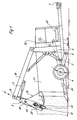
- the device shown in FIG. 1 for the removal and distribution of silage forage is preferably attached behind an agricultural tractor, not shown, for example, on the indicated farm rail 1.
- an agricultural tractor not shown, for example, on the indicated farm rail 1.
- Appropriate versions for mounting directly on the three-point hydraulic system of a tractor are possible.
- the entire device is moved backwards to a flat silo 2, where it has been brought into the lowered and illustrated working position by pivoting impellers 4 mounted on axle rockers 3 about an axis of rotation 5 of the axle rockers by means of hydraulic cylinders 6 before entering the flat silo is.
- the device essentially comprises a loading space 23 and a shield 7 protruding on its upper side beyond its rear end.
- This shield 7 is connected to a rocker arm 10 which can be pivoted overall about a pivot point 8, with a hydraulic cylinder for pivoting the shield 7 9 is provided.
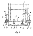
- a pair of double knives 11 consisting of two knives 12 and 13 oscillating in opposite directions.
- This pair of double knives 11 is driven by a hydraulic motor 14 with the interposition of a chain drive 15 or the like via a shaft with swash plates 17 arranged thereon, the swash plates 17 being provided with swash arms 19 which are in a pocket of a bearing block 20 of the two knives 12 and 13 intervention.
- the bearing block 20 is firmly connected to a knife 12 or 13.
- Each knife 12 or 13 has a corresponding recess in the area in which its opposite knife 12 or 13 carries a bearing block 20.
- 7 side cutting devices are arranged on both sides of the shield, each consisting of a pair of knives 25 with side knives 26 and 27.
- pairs of double knives 25 are pivotally connected at a pivot point 28 to the shield 7. Below this fulcrum 28, the shaft 16 engages via a double eccentric 40 in correspondingly designed slots 29 in the side knives 26 and 27. If the shaft 16 is driven, a counter-oscillating drive of the two side knives 26 and 27 of the two knife pairs 25 takes place via the double eccentrics 40.
Landscapes
- Life Sciences & Earth Sciences (AREA)
- Environmental Sciences (AREA)
- Threshing Machine Elements (AREA)
Claims (6)
- Dispositif pour le prélèvement et la répartition de fourrage ensilé, depuis des silos plats, lequel est constitué d'un espace de chargement (23) pouvant être monté derrière un tracteur agricole, pouvant être déplacé en hauteur, depuis une position de transport jusqu'à une position de travail située au sol, sur le côté supérieur duquel est monté un bras oscillant, pouvant pivoter par des moyens hydrauliques, faisant saillie au-delà de l'extrémité arrière de l'espace de chargement (23), avec une plaque (7) montée de manière à pouvoir pivoter à son extrémité, ladite plaque (7) étant pourvue, en sa limite inférieure, de couteaux (12, 13), parmi lesquels l'un au moins peut être entraîné de manière oscillante, caractérisé en ce que l'entraînement pour chaque couteau (12, 13) pouvant être entraîné est constitué de plateaux oscillants (17) montés sur un arbre (16) pouvant être entraîné et qu'est disposé, sur au moins l'un des côtés de la plaque (7), un dispositif de coupe latéral, qui est constitué respectivement de deux couteaux latéraux (26, 27), parmi lesquels au moins l'un est monté de manière pendulaire sur la plaque (7), en étant décalé par rapport à l'arbre (16) s'avançant au-delà de la plaque (7), et peut être entraîné de manière oscillante par l'intermédiaire d'un excentrique monté sur l'arbre (16).
- Dispositif selon la revendication 1, caractérisé en ce que les deux couteaux latéraux (26, 27) sont montés de manière pendulaire sur la plaque (7) et peuvent chacun être entraînés par un double excentrique (40) venant en prise dans des fentes (29) des deux couteaux latéraux (26, 27).
- Dispositif selon l'une quelconque des revendications 1 ou 2, caractérisé en ce que les couteaux latéraux (26, 27) sont conçus en forme de segments.
- Dispositif selon l'une quelconque des revendications 1 à 3, caractérisé en ce que des plateaux oscillants (17) sont prévus, d'une manière connue en soi, sur l'arbre (16), pour entraîner chaque couteau (12, 13) pouvant être entraîné, de la plaque (7).
- Dispositif selon l'une quelconque des revendications 1 à 4, caractérisé en ce qu'un moteur hydraulique (14) est prévu pour entraîner l'arbre (16).
- Dispositif selon la revendication 5, caractérisé en ce que une transmission par chaîne (15) ou similaire est disposée entre le moteur hydraulique (14) et l'arbre (16).
Applications Claiming Priority (4)
| Application Number | Priority Date | Filing Date | Title |
|---|---|---|---|
| DE3807228 | 1988-03-05 | ||
| DE19883807228 DE3807228A1 (de) | 1988-03-05 | 1988-03-05 | Geraet zur entnahme und zum verteilen von silagefutter aus flachsilos |
| DE3835431A DE3835431A1 (de) | 1988-03-05 | 1988-10-18 | Geraet zur entnahme und zum verteilen von silagefutter aus flachsilos |
| DE3835431 | 1988-10-18 |
Publications (2)
| Publication Number | Publication Date |
|---|---|
| EP0331950A1 EP0331950A1 (fr) | 1989-09-13 |
| EP0331950B1 true EP0331950B1 (fr) | 1993-10-06 |
Family
ID=25865562
Family Applications (1)
| Application Number | Title | Priority Date | Filing Date |
|---|---|---|---|
| EP89102834A Expired - Lifetime EP0331950B1 (fr) | 1988-03-05 | 1989-02-18 | Dispositif de prélèvement et de distribution de silage d'un silo plat |
Country Status (2)
| Country | Link |
|---|---|
| EP (1) | EP0331950B1 (fr) |
| DE (2) | DE3835431A1 (fr) |
Families Citing this family (8)
| Publication number | Priority date | Publication date | Assignee | Title |
|---|---|---|---|---|
| WO1991002451A2 (fr) * | 1989-08-16 | 1991-03-07 | Alois Assfalg | Dispositif pour retirer du stock de transport, comprime au moins sous pression de stockage, d'un stock de fourrage, d'un silo, ou d'une presse |
| FR2658986B1 (fr) * | 1990-03-05 | 1992-06-12 | Belair Pierre | Perfectionnement de dessilage et de chargement d'une dessileuse melangeuse pailleuse. |
| ATE122330T1 (de) * | 1990-03-26 | 1995-05-15 | Willibald Gmbh Maschinenfabrik | Vorrichtung zum umsetzen von in mieten gelagertem kompost. |
| DE9303751U1 (de) * | 1993-03-13 | 1994-07-21 | Aßfalg, Alois, 89597 Unterwachingen | Ladewagen zum Abtragen von Erntegut wie Silage, Halmgut o.dgl. aus einem Futterstock |
| FR2724810B1 (fr) * | 1994-09-28 | 1997-01-24 | Agram | Couteau de predecoupe de desileuse a pelle |
| NL9500544A (nl) * | 1995-03-21 | 1996-11-01 | Litech Bv | Inrichting voor het uitsnijden en/of verwerken van veevoer, alsmede snijbord voor een dergelijke inrichting. |
| DE19544231A1 (de) * | 1995-11-28 | 1997-06-05 | Strautmann & Soehne | Gerät zur Entnahme, zum Mischen und zum Verteilen von Silagefutter aus Flachsilos |
| DE102012109980A1 (de) * | 2012-10-19 | 2014-04-24 | B. Strautmann & Söhne GmbH & Co. KG | Schneidwerk an einer am Schwenkarm eines Futtermischwagens angeordneten Entnahmevorrichtung |
Family Cites Families (4)
| Publication number | Priority date | Publication date | Assignee | Title |
|---|---|---|---|---|
| DD79173A (fr) * | ||||
| AT249437B (de) * | 1962-01-31 | 1966-09-26 | Allgemeiner Zentralver Zur Foe | Mähwerk für insbesondere motorisch angetriebene Mähmaschinen |
| FR2591420B1 (fr) * | 1985-12-18 | 1989-03-03 | Audureau Sa | Desileuse a griffe |
| DE3602403A1 (de) * | 1986-01-28 | 1987-07-30 | Josef Berle | Vorrichtung zur entnahme von silage aus einem fahrsilo |
-
1988
- 1988-10-18 DE DE3835431A patent/DE3835431A1/de not_active Ceased
-
1989
- 1989-02-18 EP EP89102834A patent/EP0331950B1/fr not_active Expired - Lifetime
- 1989-02-18 DE DE89102834T patent/DE58905801D1/de not_active Expired - Fee Related
Also Published As
| Publication number | Publication date |
|---|---|
| EP0331950A1 (fr) | 1989-09-13 |
| DE3835431A1 (de) | 1990-04-19 |
| DE58905801D1 (de) | 1993-11-11 |
Similar Documents
| Publication | Publication Date | Title |
|---|---|---|
| DE2649140A1 (de) | Zuckerrohrerntemaschine | |
| EP0331950B1 (fr) | Dispositif de prélèvement et de distribution de silage d'un silo plat | |
| DE2947511C2 (de) | Absaugendes, ein Schlagmesserschneidwerk aufweisendes Mähwerk zum Anbringen an einem Tragfahrzeug | |
| DE2608769A1 (de) | Vorrichtung zum lostrennen von frischfutter, zum heben des losgetrennten frischfutterstuecks und zu dessen befoerderung an gewuenschten ort | |
| DE6605923U (de) | Kreiselmaehwerk | |
| EP0176057A2 (fr) | Dispositif de hachage pour matériaux organiques | |
| DE202020106292U1 (de) | Mähwerk mit Mähbalken | |
| DE3218673A1 (de) | Maehmesserantrieb fuer eine halmfruchterntemaschine | |
| EP0415466B1 (fr) | Appareil pour découper du fourrage ensilé d'un silo | |
| DE69914140T2 (de) | Fahrzeug mit Jauchunterbringer | |
| DE2338085A1 (de) | Verfahren und vorrichtung zum beseitigen von baumstuempfen | |
| DE2646639C2 (de) | Fräse zur Entnahme von Silagegut aus einem Silo | |
| DE2515571C2 (de) | Vorrichtung und Verfahren zum Lockern und Verteilen von Grüngut in einem Flachsilo | |
| EP0765598B1 (fr) | Dispositif de séparation pour désileuses de silos couloirs | |
| DE9102075U1 (de) | Gerät zur Entnahme und zum Verteilen von Silagefutter aus Flachsilos | |
| DE3201690C1 (de) | Flachsilo-Entnahmegerät | |
| DE19610590A1 (de) | Vorrichtung zum Ausschneiden und/oder Verarbeiten von Silage, als auch Schneidschild für eine solche Vorrichtung | |
| DE1482235C3 (de) | Mähwerk an landwirtschaftlichen Arbeitsmaschinen, Insbesondere Acker- | |
| DD159963A5 (de) | Einrichtung zur aufnahme von erntegut,insbesondere an einem ladewagen | |
| DE3423791A1 (de) | Aufnahme-, misch- und verteilwagen fuer futter | |
| DE3821235A1 (de) | Maehgeraet | |
| EP0950349B1 (fr) | Dispositif d'affûtage des couteaux hacheurs de machines de hachage à tambour | |
| DE1782273A1 (de) | Zerkleinerungs- und Dosiervorrichtung von in Haufen befindlichen landwirtschaftlichen Massenguetern | |
| DE3807228A1 (de) | Geraet zur entnahme und zum verteilen von silagefutter aus flachsilos | |
| DE2808764A1 (de) | Bodenbearbeitungsmaschine |
Legal Events
| Date | Code | Title | Description |
|---|---|---|---|
| PUAI | Public reference made under article 153(3) epc to a published international application that has entered the european phase |
Free format text: ORIGINAL CODE: 0009012 |
|
| AK | Designated contracting states |
Kind code of ref document: A1 Designated state(s): BE DE FR GB IT NL |
|
| 17P | Request for examination filed |
Effective date: 19891109 |
|
| 17Q | First examination report despatched |
Effective date: 19901116 |
|
| RBV | Designated contracting states (corrected) |
Designated state(s): DE FR NL |
|
| GRAA | (expected) grant |
Free format text: ORIGINAL CODE: 0009210 |
|
| AK | Designated contracting states |
Kind code of ref document: B1 Designated state(s): DE FR NL |
|
| REF | Corresponds to: |
Ref document number: 58905801 Country of ref document: DE Date of ref document: 19931111 |
|
| ET | Fr: translation filed | ||
| PLBE | No opposition filed within time limit |
Free format text: ORIGINAL CODE: 0009261 |
|
| 26N | No opposition filed | ||
| PGFP | Annual fee paid to national office [announced via postgrant information from national office to epo] |
Ref country code: FR Payment date: 19960215 Year of fee payment: 8 |
|
| PGFP | Annual fee paid to national office [announced via postgrant information from national office to epo] |
Ref country code: NL Payment date: 19960229 Year of fee payment: 8 |
|
| PG25 | Lapsed in a contracting state [announced via postgrant information from national office to epo] |
Ref country code: NL Effective date: 19970901 |
|
| PG25 | Lapsed in a contracting state [announced via postgrant information from national office to epo] |
Ref country code: FR Effective date: 19971030 |
|
| NLV4 | Nl: lapsed or anulled due to non-payment of the annual fee |
Effective date: 19970901 |
|
| REG | Reference to a national code |
Ref country code: FR Ref legal event code: ST |
|
| PGFP | Annual fee paid to national office [announced via postgrant information from national office to epo] |
Ref country code: DE Payment date: 19990428 Year of fee payment: 11 |
|
| PG25 | Lapsed in a contracting state [announced via postgrant information from national office to epo] |
Ref country code: DE Free format text: LAPSE BECAUSE OF NON-PAYMENT OF DUE FEES Effective date: 20001201 |