EP0331955A1 - Bestandteile einer Vorrichtung zum Herstellen einer Reifenverstärkung - Google Patents
Bestandteile einer Vorrichtung zum Herstellen einer Reifenverstärkung Download PDFInfo
- Publication number
- EP0331955A1 EP0331955A1 EP89102864A EP89102864A EP0331955A1 EP 0331955 A1 EP0331955 A1 EP 0331955A1 EP 89102864 A EP89102864 A EP 89102864A EP 89102864 A EP89102864 A EP 89102864A EP 0331955 A1 EP0331955 A1 EP 0331955A1
- Authority
- EP
- European Patent Office
- Prior art keywords
- retaining means
- wire
- groove
- lever
- means according
- Prior art date
- Legal status (The legal status is an assumption and is not a legal conclusion. Google has not performed a legal analysis and makes no representation as to the accuracy of the status listed.)
- Granted
Links
Images




Classifications
-
- B—PERFORMING OPERATIONS; TRANSPORTING
- B29—WORKING OF PLASTICS; WORKING OF SUBSTANCES IN A PLASTIC STATE IN GENERAL
- B29D—PRODUCING PARTICULAR ARTICLES FROM PLASTICS OR FROM SUBSTANCES IN A PLASTIC STATE
- B29D30/00—Producing pneumatic or solid tyres or parts thereof
- B29D30/06—Pneumatic tyres or parts thereof (e.g. produced by casting, moulding, compression moulding, injection moulding, centrifugal casting)
- B29D30/38—Textile inserts, e.g. cord or canvas layers, for tyres; Treatment of inserts prior to building the tyre
-
- B—PERFORMING OPERATIONS; TRANSPORTING
- B29—WORKING OF PLASTICS; WORKING OF SUBSTANCES IN A PLASTIC STATE IN GENERAL
- B29D—PRODUCING PARTICULAR ARTICLES FROM PLASTICS OR FROM SUBSTANCES IN A PLASTIC STATE
- B29D30/00—Producing pneumatic or solid tyres or parts thereof
- B29D30/06—Pneumatic tyres or parts thereof (e.g. produced by casting, moulding, compression moulding, injection moulding, centrifugal casting)
- B29D30/08—Building tyres
- B29D30/10—Building tyres on round cores, i.e. the shape of the core is approximately identical with the shape of the completed tyre
- B29D30/16—Applying the layers; Guiding or stretching the layers during application
- B29D30/1635—Applying the layers; Guiding or stretching the layers during application by feeding a continuous band and moving it back and forth (zig-zag) to form an annular element
-
- B—PERFORMING OPERATIONS; TRANSPORTING
- B29—WORKING OF PLASTICS; WORKING OF SUBSTANCES IN A PLASTIC STATE IN GENERAL
- B29D—PRODUCING PARTICULAR ARTICLES FROM PLASTICS OR FROM SUBSTANCES IN A PLASTIC STATE
- B29D30/00—Producing pneumatic or solid tyres or parts thereof
- B29D30/06—Pneumatic tyres or parts thereof (e.g. produced by casting, moulding, compression moulding, injection moulding, centrifugal casting)
- B29D30/08—Building tyres
- B29D30/34—Building tyres by jointly covering two bead-rings, located parallel to each other at a distance apart, with fabric or cord layers
-
- B—PERFORMING OPERATIONS; TRANSPORTING
- B60—VEHICLES IN GENERAL
- B60C—VEHICLE TYRES; TYRE INFLATION; TYRE CHANGING; CONNECTING VALVES TO INFLATABLE ELASTIC BODIES IN GENERAL; DEVICES OR ARRANGEMENTS RELATED TO TYRES
- B60C9/00—Reinforcements or ply arrangement of pneumatic tyres
- B60C9/02—Carcasses
-
- B—PERFORMING OPERATIONS; TRANSPORTING
- B29—WORKING OF PLASTICS; WORKING OF SUBSTANCES IN A PLASTIC STATE IN GENERAL
- B29D—PRODUCING PARTICULAR ARTICLES FROM PLASTICS OR FROM SUBSTANCES IN A PLASTIC STATE
- B29D30/00—Producing pneumatic or solid tyres or parts thereof
- B29D30/06—Pneumatic tyres or parts thereof (e.g. produced by casting, moulding, compression moulding, injection moulding, centrifugal casting)
- B29D30/08—Building tyres
- B29D30/10—Building tyres on round cores, i.e. the shape of the core is approximately identical with the shape of the completed tyre
- B29D30/16—Applying the layers; Guiding or stretching the layers during application
- B29D2030/1664—Details, accessories or auxiliary operations not provided for in the other subgroups of B29D30/00
- B29D2030/1678—Details, accessories or auxiliary operations not provided for in the other subgroups of B29D30/00 the layers being applied being substantially continuous, i.e. not being cut before the application step
Definitions
- the present invention relates to the manufacture of tires. It relates to the type of device described in patent application EP 243,851.
- this device comprises means for retaining the wire, carried by levers designated by the term "support arm” in patent application EP 243 851.
- This device also includes means for presenting the wire to the means of detention.
- these presentation means consist of a rotary arm ensuring the unwinding and the attachment of wire to the retaining means; the wire retaining means are constituted by a pair of hooks and the wire is unwound from an orifice located at the end of the rotary arm.
- the object of the present invention is to propose other means of retention and other means of presenting the wire, which are particularly suitable (although this is not limiting) when fairly stiff wire is used, such as for example a cable. metallic.
- a wire retaining means for an apparatus for manufacturing tires said apparatus being of the type comprising two coaxial rings of levers the end of which carries said retaining means is characterized in that it essentially defines a groove limited by two lips, the bottom of said groove describing an unclosed curve.
- thread must be understood in the most general sense to designate the filamentary reinforcement material, monofilament or multifilament, plied, cable ...
- the present invention although of application very wide possible, is specifically adapted to the use of wires such as metallic reinforcing cords, that is to say wires which cannot be subjected to a small radius bend without undergoing permanent deformation.
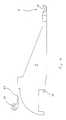
- lever 2 which, as taught by the European patent already cited, has a hinge point 21 and a control point 22. At its end, it carries wire retaining means. It is essentially a groove 3 bounded by two lips 31 and 32 (see Figures 2 and 3). But it could also be a plurality of small hooks or lugs (at least three) arranged so as to form, to define a groove limited by two lips which, provided that the thread tension is controlled, can fulfill an equivalent function. Thus, the wire 4 can engage on the groove 3 as it would around a pulley.
- the wires 4 of the reinforcement must be oriented substantially radially.
- a rod is threaded in loops formed for this purpose. In order for this threading to be possible, this loop must be arranged substantially radially.
- the bottom 30 of said groove 3 defines an unclosed planar curve, included in a substantially radial plane. This curve is not closed because it does not need to be. Even taking into account the folding movement, the wire 4 will only be supported on the groove 3 on an arc less than 360 ° (For the folding movement, see FIGS. 10 et seq.).
- the extension 20 at the end of the lever 2 constitutes one 31 of the lips 31 and 32 of the groove 3.
- This extension 20 is constituted by a sheet radial plane, just like the lever 2 itself.
- the levers 2 are also used, the end of which has, for this purpose, a recess 28 on the radially outer side.
- This recess 28 serves as a template for the installation of a rod.
- the curve defined by the bottom 30 of the groove 3 has the general appearance of a partial oval, which bypasses the recess 28, so that the latter is located inside the groove 3.
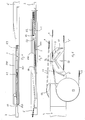
- a rotary arm 5 (see FIG. 4: axis of rotation 50 and movement according to arrow F5) ensures the unwinding and the attachment of the wire 4 to the grooves 3.
- This rotary arm 5 carries at its end presentation means which we will now describe an execution specifically designed to be used with the retaining means 3 previously described.
- the assembly constituted by wire retaining means and a wire presentation means for a tire manufacturing device said device being of the type comprising two coaxial rings of levers, the end of which carries retaining means as defined above.
- the presentation means have the appearance of a fork constituted by two planar elements 590 and 591, parallel to the movement of said presentation means, separated from each other by the thickness "e" of the means of retainer 3, the wire 4 being brought and unwound by one of the two planar elements.
- this rotary arm 5 also comprises a return pulley 52 located in a plane perpendicular to the axis of rotation 50 of the rotary arm 5, and therefore in the plane of movement of the presentation means.
- a passage 59 for the groove 3 This passage 59 is disposed between the return pulley 52 and the axis of rotation 50.
- the radius of the return pulley 52 must be sufficient so as not to impart permanent deformation to the wire 4.
- the use of a pulley rather than a groove or an equivalent curved conduit makes it possible to avoid wear by friction at a place where the contact pressure of the wire 4 on the unwinding member is high.
- the ramp 53 brings the strand 41 of the wire 4 out of the plane of rotation of the strand 42 located between the axis of rotation 50 and the pulley 52.
- This strand 41 is confined between the planar elements 590, 591, this which allows the attachment to throat hit 3.
- the clearance (of) is anyway less than the diameter of the wire 4 so that the latter cannot escape the groove 3 when the latter crosses the passage 59.
- One 590 of these two planar elements 590, 591 carries the return pulley 52.
- the passage 59 for the groove 3 appears between the planar elements 590 and 591 and next to the pulley 52.
- the retaining means on each of the two axially opposite crowns must be compatible with the unwinding means of the rotary arm 5, which is unique. This is why the ends of the levers 2 of the left crown ( Figures 6, 7, 8 and 10) and those of the right crown ( Figure 9) are symmetrical with respect to a plane ⁇ perpendicular to the axis of the crowns. (visible in FIG. 10) and comprising the axis of rotation 50 of the rotary arm 5. Therefore the levers 2 are not interchangeable between the left and right crowns, the position of the groove 3 relative to the sheet metal constituting the extension 20 of lever 2 being reversed in one case relative to the other.
- the attachment of the wire 4 to a groove 3 on the left begins on the middle zone 3g of the groove 3, while on the other side (there where the presentation of the wire 4 takes place while the rotary arm is approaching radially from the axis of the crowns), the attachment begins on the terminal zone 3d of the groove 3.
- the shape of the groove 3 is however identical on the left and on the right, as well as the presence of a recess 28 on each side, these characteristics being dictated mainly after the execution of the manufacturing process.
- the references 4 ′, 4 ⁇ , 4 ′′′ indicate successive positions taken by the wire 4 when it is hooked to the grooves 3.
- the groove 3 must then authorize the detachment of the wire 4 by the sole pursuit of the movement of axial approximation of the ends of the levers 2 towards the core 7.
- the lip 32 that is to say that located on the side of the groove 3 opposite the fixing of the latter on the lever 2 gradually decreases in height at the very end of the lever 2. This is achieved by a chamfer 33 clearly visible in FIGS. 2 and 3, which allows detaching the wire 4 without the need for a relative movement (in the axis of the core) between the rod 45 and the retaining means constituted by the grooves 3.
- the tilting movement of the levers 2 results from the combined action of controlling the axial displacement of all the articulation points 21, of pressing on the control points 22, and of the tension reaction of the thread. 4.
- the axial approximation of the groove 3 is accompanied by a radial movement towards the axis of the crowns of levers 2. It this results in a rotation R3 of the groove 3 relative to the orientation of the wires 4 (see FIGS. 10 to 14).
- the strand 43 of the wire 4 therefore engages on the chamfer 33, which pushes the wire 4 to leave the groove 3.
- the rods 45 are released from the levers 2 and pushed towards the core 7 by the flanges 81 (FIGS. 15 and 16), by virtue of a relative axial movement of the said flanges 81 relative to the levers 2.
- the fingers 80 are passed axially outside the rods 45, as shown in FIG. 12.
- FIGS. 10 to 16 clearly show all the movements of the various organs, shown diagrammatically by the arrows.
- the distance between two adjacent strands of the wire 4 retained by the same groove 3 can be adjusted by tilting the end of said groove 3 in the peripheral direction by an amount corresponding to a maximum of half the difference between two adjacent retaining means. Otherwise the strands of wire 4 leaving the groove 3 on either side thereof tend to remain in the same meridian plane and to be juxtaposed.
Landscapes
- Engineering & Computer Science (AREA)
- Mechanical Engineering (AREA)
- Textile Engineering (AREA)
- Tyre Moulding (AREA)
- Ropes Or Cables (AREA)
- Heating, Cooling, Or Curing Plastics Or The Like In General (AREA)
- Percussive Tools And Related Accessories (AREA)
- Light Guides In General And Applications Therefor (AREA)
Priority Applications (1)
| Application Number | Priority Date | Filing Date | Title |
|---|---|---|---|
| AT89102864T ATE75660T1 (de) | 1988-03-07 | 1989-02-20 | Bestandteile einer vorrichtung zum herstellen einer reifenverstaerkung. |
Applications Claiming Priority (2)
| Application Number | Priority Date | Filing Date | Title |
|---|---|---|---|
| FR8803005A FR2628033B1 (fr) | 1988-03-07 | 1988-03-07 | Moyens de retenue de fil pour appareil de fabrication de pneumatiques et ensemble constitue par lesdits moyens de retenue et par des moyens de presentation du fil |
| FR8803005 | 1988-03-07 |
Publications (2)
| Publication Number | Publication Date |
|---|---|
| EP0331955A1 true EP0331955A1 (de) | 1989-09-13 |
| EP0331955B1 EP0331955B1 (de) | 1992-05-06 |
Family
ID=9364070
Family Applications (1)
| Application Number | Title | Priority Date | Filing Date |
|---|---|---|---|
| EP89102864A Expired - Lifetime EP0331955B1 (de) | 1988-03-07 | 1989-02-20 | Bestandteile einer Vorrichtung zum Herstellen einer Reifenverstärkung |
Country Status (10)
| Country | Link |
|---|---|
| US (1) | US5043042A (de) |
| EP (1) | EP0331955B1 (de) |
| JP (1) | JP2767749B2 (de) |
| KR (1) | KR890014248A (de) |
| AT (1) | ATE75660T1 (de) |
| BR (1) | BR8901056A (de) |
| CA (1) | CA1340051C (de) |
| DE (1) | DE68901405D1 (de) |
| ES (1) | ES2032063T3 (de) |
| FR (1) | FR2628033B1 (de) |
Citations (3)
| Publication number | Priority date | Publication date | Assignee | Title |
|---|---|---|---|---|
| US2139840A (en) * | 1936-06-06 | 1938-12-13 | Charles W Mckone | Process of making pneumatic tires |
| DE1291112B (de) * | 1962-04-03 | 1969-03-20 | Fairchild Stratos Corp | Geraet zum Aufwickeln von Verstaerkungsfaeden auf eine Reifenform |
| EP0243851A1 (de) * | 1986-04-25 | 1987-11-04 | MICHELIN & CIE (Compagnie Générale des Etablissements Michelin) Société dite: | Verfahren und Vorrichtung zur Herstellung von Verstärkungen für Reifen |
Family Cites Families (14)
| Publication number | Priority date | Publication date | Assignee | Title |
|---|---|---|---|---|
| US1321402A (en) * | 1919-11-11 | Method for making pneumatic tires | ||
| US852855A (en) * | 1906-08-20 | 1907-05-07 | Thomas Sloper | Machinery for use in the manufacture of pneumatic tires. |
| US1349390A (en) * | 1915-04-17 | 1920-08-10 | James A Swinehart | Process of making elastic vehicle-tires |
| US1328006A (en) * | 1916-09-18 | 1920-01-13 | Nelson W Mcleod | Method of making pneumatic tires |
| US1259997A (en) * | 1916-11-06 | 1918-03-19 | Walter Kline | Tire-cording machine. |
| US3674584A (en) * | 1969-05-22 | 1972-07-04 | Deering Milliken Res Corp | Method and apparatus for positioning a continuous thread or cord on a support surface |
| US3602965A (en) * | 1969-06-17 | 1971-09-07 | Kimberly Clark Co | Apparatus for forming a nonwoven web of criss-cross threads |
| GB1573714A (en) * | 1976-12-13 | 1980-08-28 | Hellenic Plastics Rubber | Bonded non-woven net structures and articles incorporating such structures |
| US4206009A (en) * | 1977-03-23 | 1980-06-03 | Amf Incorporated | Micro-computer and programmer for application of tire tread material |
| MX153272A (es) * | 1978-09-08 | 1986-09-08 | Lim Kunststoff Tech Gmbh | Procedimiento y aparato para la fabricacion de una llanta neumatica mejorada |
| WO1981001119A1 (en) * | 1979-10-29 | 1981-04-30 | Caterpillar Tractor Co | Apparatus and method for holding and tacking material |
| IN157066B (de) * | 1980-10-16 | 1986-01-04 | Bates W & A Ltd | |
| IN157723B (de) * | 1980-10-16 | 1986-05-24 | Bates W & A Ltd | |
| JPS59500169A (ja) * | 1982-02-11 | 1984-02-02 | ヤ−ヌス ゲゼルシヤフト ミツト ベシユレンクテル ハフトウング | ラジアルタイヤならびにその製造方法および装置 |
-
1988
- 1988-03-07 FR FR8803005A patent/FR2628033B1/fr not_active Expired - Fee Related
-
1989
- 1989-02-20 DE DE8989102864T patent/DE68901405D1/de not_active Expired - Lifetime
- 1989-02-20 ES ES198989102864T patent/ES2032063T3/es not_active Expired - Lifetime
- 1989-02-20 EP EP89102864A patent/EP0331955B1/de not_active Expired - Lifetime
- 1989-02-20 AT AT89102864T patent/ATE75660T1/de not_active IP Right Cessation
- 1989-03-06 KR KR1019890002728A patent/KR890014248A/ko not_active Withdrawn
- 1989-03-06 JP JP1053594A patent/JP2767749B2/ja not_active Expired - Lifetime
- 1989-03-07 CA CA000592931A patent/CA1340051C/fr not_active Expired - Fee Related
- 1989-03-07 BR BR898901056A patent/BR8901056A/pt not_active Application Discontinuation
-
1990
- 1990-08-09 US US07/565,886 patent/US5043042A/en not_active Expired - Lifetime
Patent Citations (3)
| Publication number | Priority date | Publication date | Assignee | Title |
|---|---|---|---|---|
| US2139840A (en) * | 1936-06-06 | 1938-12-13 | Charles W Mckone | Process of making pneumatic tires |
| DE1291112B (de) * | 1962-04-03 | 1969-03-20 | Fairchild Stratos Corp | Geraet zum Aufwickeln von Verstaerkungsfaeden auf eine Reifenform |
| EP0243851A1 (de) * | 1986-04-25 | 1987-11-04 | MICHELIN & CIE (Compagnie Générale des Etablissements Michelin) Société dite: | Verfahren und Vorrichtung zur Herstellung von Verstärkungen für Reifen |
Also Published As
| Publication number | Publication date |
|---|---|
| FR2628033A1 (fr) | 1989-09-08 |
| ATE75660T1 (de) | 1992-05-15 |
| FR2628033B1 (fr) | 1990-06-29 |
| BR8901056A (pt) | 1989-10-24 |
| JPH01272445A (ja) | 1989-10-31 |
| DE68901405D1 (de) | 1992-06-11 |
| KR890014248A (ko) | 1989-10-23 |
| EP0331955B1 (de) | 1992-05-06 |
| CA1340051C (fr) | 1998-09-22 |
| US5043042A (en) | 1991-08-27 |
| JP2767749B2 (ja) | 1998-06-18 |
| ES2032063T3 (es) | 1993-01-01 |
Similar Documents
| Publication | Publication Date | Title |
|---|---|---|
| EP0493182A1 (de) | Rohrschelle | |
| FR2560922A1 (fr) | Dispositif pour empecher l'application d'une tension excessive au moteur a ressort d'un store de fenetre | |
| EP1231050B1 (de) | Vorrichtung mit Schwingarm zur Herstellung einer Luftreifenverstärkung aus einem Draht | |
| EP1231049B1 (de) | Schwingarmvorrichtung zur Herstellung einer Reifenverstärkungsstruktur mit einem einzigen Reifenkord | |
| EP0331955B1 (de) | Bestandteile einer Vorrichtung zum Herstellen einer Reifenverstärkung | |
| EP0353511B1 (de) | Bestandteile einer Vorrichtung zum Herstellen einer Reifenverstärkung | |
| FR2683491A1 (fr) | Convertisseur d'energie pour ceinture de securite. | |
| LU81812A1 (fr) | Procede et appareil pour la fabrication de tringles pour talons de pneumatiques | |
| FR2472694A1 (fr) | Organe de retenue de galet ou contre-came pour frein | |
| FR2770541A1 (fr) | Dispositif d'accrochage d'une lisse a un cordon, lisse de metier a tisser comprenant un tel dispositif d'accrochage et metier a tisser equipe d'une telle lisse | |
| WO2002030176A1 (fr) | Devidoir suspendu, notamment pour cultures | |
| FR2764932A1 (fr) | Procede de montage de cables sur un tambour de leve-vitre de vehicule automobile et dispositif pour la mise en oeuvre de ce procede | |
| FR2995762A1 (fr) | Porte-bobine de fil de montage pour la fabrication de mouche de peche et procede de montage d'un dubbing utilisant ce porte-bobine | |
| EP0088708A2 (de) | Vorrichtung zum Zentrieren und Fassen von Spulenhülsen während eines Spulvorganges | |
| EP0208684B1 (de) | Verfahren und vorrichtung zum thermischen behandeln eines dünnen garnes | |
| FR1274750A (fr) | Perfectionnements aux berceaux pour bobines | |
| FR2802193A1 (fr) | Enrouleur de sangle, mecanisme de manoeuvre d'un volet ou store roulant comprenant un tel enrouleur et procede de reglage de la tension du ressort d'un tel enrouleur | |
| EP1824666B1 (de) | Vorrichtung zur herstellung einer verstärkung für einen luftreifen | |
| FR2504104A1 (fr) | Dispositif permettant le positionnement et le maintien d'un tube support de fil lors d'une operation de bobinage | |
| EP4538544A1 (de) | Blockiervorrichtung mit beweglichem nocken und verfahren zur herstellung einer verriegelungsvorrichtung mit beweglichem nocken | |
| WO2023208916A1 (fr) | Frein à tambour de véhicule automobile | |
| CH256472A (fr) | Dispositif servant à bobiner une matière en forme de faisceau. | |
| FR3053995A1 (fr) | Dispositif de verrouillage automatique d'un tablier de systeme d'occultation | |
| FR2595777A1 (fr) | Dispositif automatique de reglage de freins a machoires interieures | |
| WO2024068285A1 (fr) | Tambour de fabrication de bandage pourvu d'un dispositif de fixation embarqué comprenant une lame de serrage escamotable |
Legal Events
| Date | Code | Title | Description |
|---|---|---|---|
| PUAI | Public reference made under article 153(3) epc to a published international application that has entered the european phase |
Free format text: ORIGINAL CODE: 0009012 |
|
| 17P | Request for examination filed |
Effective date: 19890220 |
|
| AK | Designated contracting states |
Kind code of ref document: A1 Designated state(s): AT BE CH DE ES FR GB GR IT LI LU NL SE |
|
| 17Q | First examination report despatched |
Effective date: 19910423 |
|
| GRAA | (expected) grant |
Free format text: ORIGINAL CODE: 0009210 |
|
| AK | Designated contracting states |
Kind code of ref document: B1 Designated state(s): AT BE CH DE ES FR GB GR IT LI LU NL SE |
|
| PG25 | Lapsed in a contracting state [announced via postgrant information from national office to epo] |
Ref country code: NL Effective date: 19920506 Ref country code: GR Free format text: LAPSE BECAUSE OF FAILURE TO SUBMIT A TRANSLATION OF THE DESCRIPTION OR TO PAY THE FEE WITHIN THE PRESCRIBED TIME-LIMIT Effective date: 19920506 Ref country code: SE Effective date: 19920506 Ref country code: AT Effective date: 19920506 |
|
| REF | Corresponds to: |
Ref document number: 75660 Country of ref document: AT Date of ref document: 19920515 Kind code of ref document: T |
|
| REF | Corresponds to: |
Ref document number: 68901405 Country of ref document: DE Date of ref document: 19920611 |
|
| ITF | It: translation for a ep patent filed | ||
| GBT | Gb: translation of ep patent filed (gb section 77(6)(a)/1977) | ||
| NLV1 | Nl: lapsed or annulled due to failure to fulfill the requirements of art. 29p and 29m of the patents act | ||
| REG | Reference to a national code |
Ref country code: ES Ref legal event code: FG2A Ref document number: 2032063 Country of ref document: ES Kind code of ref document: T3 |
|
| PG25 | Lapsed in a contracting state [announced via postgrant information from national office to epo] |
Ref country code: LI Effective date: 19930228 Ref country code: LU Free format text: LAPSE BECAUSE OF NON-PAYMENT OF DUE FEES Effective date: 19930228 Ref country code: BE Effective date: 19930228 Ref country code: CH Effective date: 19930228 |
|
| PLBE | No opposition filed within time limit |
Free format text: ORIGINAL CODE: 0009261 |
|
| STAA | Information on the status of an ep patent application or granted ep patent |
Free format text: STATUS: NO OPPOSITION FILED WITHIN TIME LIMIT |
|
| 26N | No opposition filed | ||
| BERE | Be: lapsed |
Owner name: CIE GENERALE DES ETS MICHELIN-MICHELIN & CIE Effective date: 19930228 |
|
| REG | Reference to a national code |
Ref country code: CH Ref legal event code: PL |
|
| REG | Reference to a national code |
Ref country code: FR Ref legal event code: TP |
|
| PGFP | Annual fee paid to national office [announced via postgrant information from national office to epo] |
Ref country code: ES Payment date: 20010220 Year of fee payment: 13 |
|
| REG | Reference to a national code |
Ref country code: GB Ref legal event code: IF02 |
|
| PG25 | Lapsed in a contracting state [announced via postgrant information from national office to epo] |
Ref country code: ES Free format text: LAPSE BECAUSE OF NON-PAYMENT OF DUE FEES Effective date: 20020221 |
|
| REG | Reference to a national code |
Ref country code: ES Ref legal event code: FD2A Effective date: 20030922 |
|
| PG25 | Lapsed in a contracting state [announced via postgrant information from national office to epo] |
Ref country code: IT Free format text: LAPSE BECAUSE OF NON-PAYMENT OF DUE FEES;WARNING: LAPSES OF ITALIAN PATENTS WITH EFFECTIVE DATE BEFORE 2007 MAY HAVE OCCURRED AT ANY TIME BEFORE 2007. THE CORRECT EFFECTIVE DATE MAY BE DIFFERENT FROM THE ONE RECORDED. Effective date: 20050220 |
|
| PGFP | Annual fee paid to national office [announced via postgrant information from national office to epo] |
Ref country code: DE Payment date: 20080219 Year of fee payment: 20 Ref country code: GB Payment date: 20080220 Year of fee payment: 20 |
|
| PGFP | Annual fee paid to national office [announced via postgrant information from national office to epo] |
Ref country code: FR Payment date: 20080214 Year of fee payment: 20 |
|
| REG | Reference to a national code |
Ref country code: GB Ref legal event code: PE20 Expiry date: 20090219 |
|
| PG25 | Lapsed in a contracting state [announced via postgrant information from national office to epo] |
Ref country code: GB Free format text: LAPSE BECAUSE OF EXPIRATION OF PROTECTION Effective date: 20090219 |