EP0332051B1 - Ablauf für Überlaufrinnen von Schwimmbädern - Google Patents
Ablauf für Überlaufrinnen von Schwimmbädern Download PDFInfo
- Publication number
- EP0332051B1 EP0332051B1 EP89103671A EP89103671A EP0332051B1 EP 0332051 B1 EP0332051 B1 EP 0332051B1 EP 89103671 A EP89103671 A EP 89103671A EP 89103671 A EP89103671 A EP 89103671A EP 0332051 B1 EP0332051 B1 EP 0332051B1
- Authority
- EP
- European Patent Office
- Prior art keywords
- outlet
- opening
- drain
- perimeter
- intermediate pipe
- Prior art date
- Legal status (The legal status is an assumption and is not a legal conclusion. Google has not performed a legal analysis and makes no representation as to the accuracy of the status listed.)
- Expired - Lifetime
Links
- 230000009182 swimming Effects 0.000 title abstract description 8
- 239000000919 ceramic Substances 0.000 claims description 11
- 239000011449 brick Substances 0.000 claims 1
- 238000009423 ventilation Methods 0.000 abstract description 9
- XLYOFNOQVPJJNP-UHFFFAOYSA-N water Substances O XLYOFNOQVPJJNP-UHFFFAOYSA-N 0.000 abstract description 8
- 239000004575 stone Substances 0.000 description 9
- 239000003822 epoxy resin Substances 0.000 description 3
- 229920000647 polyepoxide Polymers 0.000 description 3
- 238000000034 method Methods 0.000 description 2
- 239000004033 plastic Substances 0.000 description 2
- 230000000630 rising effect Effects 0.000 description 2
- 239000004568 cement Substances 0.000 description 1
- 238000009413 insulation Methods 0.000 description 1
- 238000012986 modification Methods 0.000 description 1
- 230000004048 modification Effects 0.000 description 1
Images
Classifications
-
- E—FIXED CONSTRUCTIONS
- E04—BUILDING
- E04H—BUILDINGS OR LIKE STRUCTURES FOR PARTICULAR PURPOSES; SWIMMING OR SPLASH BATHS OR POOLS; MASTS; FENCING; TENTS OR CANOPIES, IN GENERAL
- E04H4/00—Swimming or splash baths or pools
- E04H4/12—Devices or arrangements for circulating water, i.e. devices for removal of polluted water, cleaning baths or for water treatment
- E04H4/1209—Treatment of water for swimming pools
- E04H4/1218—Devices for removal of polluted water; Circumferential gutters
- E04H4/1227—Circumferential gutters
Definitions
- the invention relates to an outlet for overflow channels of swimming pools or the like, consisting of an outlet opening located inside the overflow channel, to which an intermediate pipe connectable to a drain line is sealingly connected, with an outlet box being arranged between the intermediate pipe and the drain line.
- the invention is therefore based on the object of creating a drain for overflow channels from swimming pools or the like, which is designed such that no more gurgling noises occur and the occurrence of water fountains is excluded.
- the drain box is connected to the overflow channel by a ventilation channel which opens into the overflow channel above the drain opening.
- This design in particular the arrangement of the ventilation channel, prevents annoying gurgling noises from occurring when water runs off. Water fountains rising from the drain openings can no longer be determined.
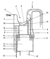
- a pool head 1 with an overflow channel 2 of an only indicated swimming pool is shown, in which the upper, lateral boundary of the swimming pool is formed by a vertical leg 3 of a ceramic drain stone 4.
- This ceramic drain stone 4 is part of the overflow channel 2, which is composed of several channel stones.
- the ceramic drain stone 4 has an opening 5 directed downwards and to the side, which consists of a drain opening 5a and a ventilation opening 5b.
- An intermediate tube 6 made of plastic connects to the lower and rear side of the ceramic drain stone 4.
- This intermediate tube 6 is designed such that it has an outlet channel 7 on the one hand and a ventilation channel 8 on the other.
- the ventilation channel 8 is only on the rear of the drain channel 7.
- a wall 9 is provided, which extends over the inner lower edge of the overflow channel 2. In its upper region, the wall 9 separates the drain opening 5a from the ventilation opening 5b.
- the drain opening 5a in the area of the ceramic drain stone 4 is covered by a drain sieve 10, for example made of plastic.
- a drain box 11 connects to the underside of the intermediate pipe 6 and is connected to a drain line 12.
- the drain box 11 has a flange 13 on which a clamping flange 14 is attached.
- a film 15, which serves for insulation, is clamped between the flange 13 and the clamping flange 14.
- the space between the clamping flange 14 and the ceramic drain stone 4 is filled with epoxy resin 16 so that the intermediate tube 6 is completely enclosed by the epoxy resin 16.
- Below the ceramic drain stone 4 there are ceramic plates 17, which are laid in a layer 18 of epoxy resin cement.
- the drain opening 5a and the vent opening 5b as separate openings in the ceramic drain block 4.
- An outlet channel 7 and a ventilation channel 8 which is completely separate therefrom can then be connected to these openings 5a, 5b.
Landscapes
- Engineering & Computer Science (AREA)
- Architecture (AREA)
- Water Supply & Treatment (AREA)
- Civil Engineering (AREA)
- Structural Engineering (AREA)
- Sink And Installation For Waste Water (AREA)
- Removal Of Floating Material (AREA)
- Filters For Electric Vacuum Cleaners (AREA)
- Percussion Or Vibration Massage (AREA)
- Farming Of Fish And Shellfish (AREA)
Description
- Die Erfindung bezieht sich auf einen Ablauf für Überlaufrinnen von Schwimmbädern oder dgl., bestehend aus einer innerhalb der Überlaufrinne befindlichen Ablauföffnung, an die ein mit einer Ablaufleitung verbindbares Zwischenrohr dichtend angeschlossen ist, wobei zwischen dem Zwischenrohr und der Ablaufleitung Abein Ablaufkasten angeordnet ist.
- Aus der DE-A 2 735 229 ist ein Ablauf für Überlaufrinnen von Schwimmbädern bekannt, bei dem in einem keramischen Ablaufstein, der Bestandteil der überlaufrinne ist, eine Ablauföffnung ausgebildet ist. An diese Ablauföffnung schließt sich dichtend ein Zwischenrohr an, welches zu einem Ablaufkasten führt. Dieser Ablaufkasten ist seinerseits mit einer Ablaufleitung verbunden. Derartige Abläufe haben den Nachteil, daß beim Ablauf von Wasser immer sogenannte Gurgelgeräusche auftreten, die insbesondere in Heil- und/oder Thermalbädern als störend empfunden werden. Darüber hinaus kann es bei solchen Abläufen vorkommen, daß dann, wenn durch das abfließende Wasser Luft im Zwischenrohr oder der Ablaufleitung gestaut wird, durch die aufsteigende Luft kleine Wasserfontänen entstehen.
- Der Erfindung liegt deshalb die Aufgabe zugrunde, einen Ablauf für Überlaufrinnen von Schwimmbädern oder dgl. zu schaffen, der so gestaltet ist, daß keinerlei Gurgelgeräusche mehr auftreten und das Entstehen von Wasserfontänen ausgeschlossen ist.
- Zur Lösung dieser Aufgabe wird gemäß der Erfindung bei einem Ablauf der eingangs beschriebenen Gattung vorgeschlagen, daß der Ablaufkasten mit der Überlaufrinne durch einen Entlüftungskanal verbunden ist, der oberhalb der Ablauföffnung in der Überlaufrinne mündet.
- Diese Ausbildung, insbesondere die Anordnung des Entlüftungskanals, verhindert, daß beim Ablauf von Wasser störende Gurgelgeräusche entstehen. Aus den Ablauföffnungen aufsteigende Wasserfontänen sind nicht mehr feststellbar.
- Weitere Merkmale der Erfindung sind in den Ansprüchen 2 - 6 offenbart.
- Die Erfindung wird nachfolgend anhand eines in einer Zeichnung dargestellten Ausführungsbeispieles näher erläutert.
- In dieser Zeichnung ist ein Beckenkopf 1 mit Überlaufrinne 2 eines nur angedeuteten Schwimmbeckens gezeigt, bei dem die obere, seitliche Begrenzung des Schwimmbeckens durch einen senkrechten Schenkel 3 eines keramischen Ablaufsteines 4 gebildet ist. Dieser keramische Ablaufstein 4 ist Bestandteil der Überlaufrinne 2, die aus mehreren Rinnensteinen zusammengesetzt ist.
- Der keramische Ablaufstein 4 weist eine nach unten und zur Seite gerichtete Öffnung 5 auf, die aus einer Ablauföffnung 5a und einer Entlüftungsöffnung 5b besteht. An die untere und rückwärtige Seite des keramischen Ablaufsteines 4 schließt sich ein Zwischenrohr 6 aus Kunststoff an. Dieses Zwischenrohr 6 ist so ausgebildet, daß es einerseits einen Ablaufkanal 7 und andererseits einen Entlüftungskanal 8 besitzt. Bei beispielsweise rechteckigem Querschnitt des Zwischenrohres 6 befindet sich der Entlüftungskanal 8 nur an der Rückseite des Ablaufkanales 7. Zwischen dem Ablaufkanal 7 und dem Entlüftungskanal 8 ist eine Wand 9 vorgesehen, die sich bis über die innere Unterkante der Überlaufrinne 2 erstreckt. In ihrem oberen Bereich trennt die Wand 9 die Ablauföffnung 5a von der Entlüftungsöffnung 5b. Zusätzlich ist die Ablauföffnung 5a im Bereich des keramischen Ablaufsteines 4 durch ein Ablaufsieb 10, beispielsweise aus Kunststoff, abgedeckt.
- An die Unterseite des Zwischenrohres 6 schließt sich ein Ablaufkasten 11 an, der mit einer Ablaufleitung 12 verbunden ist. In diesem Ausführungsbeispiel besitzt der Ablaufkasten 11 einen Flansch 13, auf dem ein Klemmflansch 14 befestigt ist. Zwischen dem Flansch 13 und dem Klemmflansch 14 ist eine Folie 15 eingespannt, die zur Isolierung dient. Der Raum zwischen dem Klemmflansch 14 und dem keramischen Ablaufstein 4 ist so mit Epoxidharz 16 ausgefüllt, daß das Zwischenrohr 6 vollständig vom Epoxidharz 16 umschlossen ist. Unterhalb des keramischen Ablaufsteines 4 schließen sich keramische Platten 17 an, die in einer Schicht 18 aus Epoxidharzkitt verlegt sind.
- In Abänderung des dargestellten Ausführungsbeispieles ist es möglich, die Ablauföffnung 5a und die Entlüftungsöffnung 5b als getrennte Öffnungen im keramischen Ablaufstein 4 vorzusehen. An diese Öffnungen 5a,5b können dann ein Ablaufkanal 7 und ein davon vollkommen getrennter Entlüftungskanal 8 angeschlossen werden.
Claims (6)
dadurch gekennzeichnet,
daß der Ablaufkasten (11) mit der Überlaufrinne (2) durch einen Entlüftungskanal (8) verbunden ist, der oberhalb der Ablauföffnung (5a) in der Überlaufrinne (2) mündet.
dadurch gekennzeichnet,
daß die Überlaufrinne (2) eine getrennte Öffnung (5b) für den Entlüftungskanal (8) aufweist.
dadurch gekennzeichnet,
daß die Entlüftungsöffnung (5b) und die Ablauföffnung (5a) als gemeinsame Öffnung (5) ausgebildet sind und die Entlüftungsöffnung (5b) von der Ablauföffnung (5a) durch eine hochgezogene Wand (9) des Zwischenrohres (6) getrennt ist.
dadurch gekennzeichnet,
daß das Zwischenrohr (6) und/oder der Entlüftungskanal (8) aus Kunststoff gebildet ist.
dadurch gekennzeichnet,
daß das Zwischenrohr (6,7) und der Entlüftungskanal (9) einstückig ausgebildet sind.
dadurch gekennzeichnet,
daß die Ablauföffnung (5a) und die Entlüftungsöffnung (5b) in einem keramischen Ablaufstein (4) angeordnet sind.
Priority Applications (1)
| Application Number | Priority Date | Filing Date | Title |
|---|---|---|---|
| AT89103671T ATE76673T1 (de) | 1988-03-09 | 1989-03-02 | Ablauf fuer ueberlaufrinnen von schwimmbaedern. |
Applications Claiming Priority (2)
| Application Number | Priority Date | Filing Date | Title |
|---|---|---|---|
| DE3807674 | 1988-03-09 | ||
| DE3807674A DE3807674C1 (de) | 1988-03-09 | 1988-03-09 |
Publications (2)
| Publication Number | Publication Date |
|---|---|
| EP0332051A1 EP0332051A1 (de) | 1989-09-13 |
| EP0332051B1 true EP0332051B1 (de) | 1992-05-27 |
Family
ID=6349217
Family Applications (1)
| Application Number | Title | Priority Date | Filing Date |
|---|---|---|---|
| EP89103671A Expired - Lifetime EP0332051B1 (de) | 1988-03-09 | 1989-03-02 | Ablauf für Überlaufrinnen von Schwimmbädern |
Country Status (3)
| Country | Link |
|---|---|
| EP (1) | EP0332051B1 (de) |
| AT (1) | ATE76673T1 (de) |
| DE (2) | DE3807674C1 (de) |
Family Cites Families (2)
| Publication number | Priority date | Publication date | Assignee | Title |
|---|---|---|---|---|
| FR1244268A (fr) * | 1959-01-07 | 1960-10-21 | Procédé d'écoulement des eaux sur les pourtours des piscines et dalles pour caniveaux d'écoulement des piscines | |
| DE2735229A1 (de) * | 1977-08-04 | 1979-02-15 | Agrob Ag | Beckenkopfdichtung fuer schwimmbecken, insbesondere in hallenbaedern, und verfahren zu ihrer herstellung |
-
1988
- 1988-03-09 DE DE3807674A patent/DE3807674C1/de not_active Expired
-
1989
- 1989-03-02 EP EP89103671A patent/EP0332051B1/de not_active Expired - Lifetime
- 1989-03-02 AT AT89103671T patent/ATE76673T1/de not_active IP Right Cessation
- 1989-03-02 DE DE8989103671T patent/DE58901513D1/de not_active Expired - Lifetime
Also Published As
| Publication number | Publication date |
|---|---|
| DE58901513D1 (de) | 1992-07-02 |
| ATE76673T1 (de) | 1992-06-15 |
| EP0332051A1 (de) | 1989-09-13 |
| DE3807674C1 (de) | 1989-04-06 |
Similar Documents
| Publication | Publication Date | Title |
|---|---|---|
| CH652776A5 (de) | Bordstein. | |
| DE3209058C3 (de) | Abwasser-Geruchsverschluß | |
| DE3807674C1 (de) | ||
| DE602004001254T3 (de) | Dreieckige Ablaufvorrichtung | |
| DE3918321A1 (de) | Ablauf mit einem wassergeruchsverschlusseinsatz | |
| EP0108272A1 (de) | Badebecken mit Wirbeldüsen | |
| DE8803147U1 (de) | Ablauf für Überlaufrinnen von Schwimmbädern | |
| DE4226709C2 (de) | Abwasserbecken mit Überfallkante | |
| DE19737728A1 (de) | Schwimmbecken | |
| DE2550520A1 (de) | Schwimmbeckenrandkonstruktion | |
| DE4335545A1 (de) | Lichtkuppel | |
| DE3328613A1 (de) | Bodenablauf | |
| DE29612521U1 (de) | Aufnahmevorrichtung für Regenwasser | |
| DE538901C (de) | Entlueftungseinrichtung fuer Abtrittbecken | |
| DE2302146C3 (de) | Belebungsbecken für Kläranlagen | |
| DE2534524A1 (de) | Luftfeuchtigkeitsregler in form eines wandbildes | |
| DE3506745C1 (de) | Künstlicher Teich | |
| DE4336228A1 (de) | Regenbecken für Abwasseranlagen mit einem Überlauf für geklärtes Wasser | |
| DE29502650U1 (de) | Falzziegel | |
| DE2535239C2 (de) | ||
| DE3247152A1 (de) | Sickerstrecke als auslaufbauwerk fuer abwasser- und schoenungsteiche | |
| DE2005582A1 (de) | Bodenwasserablauf | |
| DE8117939U1 (de) | Randstein fuer schwimmbecken | |
| DE4339598A1 (de) | Emscherbrunnen | |
| DE2623367A1 (de) | Oberflaechenreiniger fuer ein schwimmbecken |
Legal Events
| Date | Code | Title | Description |
|---|---|---|---|
| PUAI | Public reference made under article 153(3) epc to a published international application that has entered the european phase |
Free format text: ORIGINAL CODE: 0009012 |
|
| AK | Designated contracting states |
Kind code of ref document: A1 Designated state(s): AT BE CH DE ES FR GB GR IT LI LU NL SE |
|
| 17P | Request for examination filed |
Effective date: 19900226 |
|
| 17Q | First examination report despatched |
Effective date: 19910322 |
|
| GRAA | (expected) grant |
Free format text: ORIGINAL CODE: 0009210 |
|
| AK | Designated contracting states |
Kind code of ref document: B1 Designated state(s): AT BE CH DE ES FR GB GR IT LI LU NL SE |
|
| PG25 | Lapsed in a contracting state [announced via postgrant information from national office to epo] |
Ref country code: SE Effective date: 19920527 Ref country code: ES Free format text: THE PATENT HAS BEEN ANNULLED BY A DECISION OF A NATIONAL AUTHORITY Effective date: 19920527 Ref country code: GR Free format text: LAPSE BECAUSE OF FAILURE TO SUBMIT A TRANSLATION OF THE DESCRIPTION OR TO PAY THE FEE WITHIN THE PRESCRIBED TIME-LIMIT Effective date: 19920527 |
|
| REF | Corresponds to: |
Ref document number: 76673 Country of ref document: AT Date of ref document: 19920615 Kind code of ref document: T |
|
| REF | Corresponds to: |
Ref document number: 58901513 Country of ref document: DE Date of ref document: 19920702 |
|
| ITF | It: translation for a ep patent filed | ||
| ET | Fr: translation filed | ||
| GBT | Gb: translation of ep patent filed (gb section 77(6)(a)/1977) | ||
| RAP2 | Party data changed (patent owner data changed or rights of a patent transferred) |
Owner name: WACH, JOHANN FRANZ Owner name: KERAMCHEMIE GMBH |
|
| REG | Reference to a national code |
Ref country code: CH Ref legal event code: PUE Owner name: KERAMCHEMIE GMBH |
|
| REG | Reference to a national code |
Ref country code: GB Ref legal event code: 732E |
|
| NLT2 | Nl: modifications (of names), taken from the european patent patent bulletin |
Owner name: KERAMCHEMIE GMBH TE SIERSHAHN EN JOHANN FRANZ WACH |
|
| PLBE | No opposition filed within time limit |
Free format text: ORIGINAL CODE: 0009261 |
|
| STAA | Information on the status of an ep patent application or granted ep patent |
Free format text: STATUS: NO OPPOSITION FILED WITHIN TIME LIMIT |
|
| 26N | No opposition filed | ||
| NLS | Nl: assignments of ep-patents |
Owner name: KERAMCHEMIE GMBH TE SIERSHAHN EN JOHANN FRANZ WACH |
|
| REG | Reference to a national code |
Ref country code: FR Ref legal event code: TP |
|
| ITPR | It: changes in ownership of a european patent |
Owner name: CESSIONE;JOHANN FRANZ WACH ; KERAMCHEMIE GMBH |
|
| EPTA | Lu: last paid annual fee | ||
| PGFP | Annual fee paid to national office [announced via postgrant information from national office to epo] |
Ref country code: GB Payment date: 20000315 Year of fee payment: 12 |
|
| PGFP | Annual fee paid to national office [announced via postgrant information from national office to epo] |
Ref country code: BE Payment date: 20000322 Year of fee payment: 12 |
|
| PGFP | Annual fee paid to national office [announced via postgrant information from national office to epo] |
Ref country code: LU Payment date: 20000323 Year of fee payment: 12 |
|
| PGFP | Annual fee paid to national office [announced via postgrant information from national office to epo] |
Ref country code: NL Payment date: 20000331 Year of fee payment: 12 |
|
| PG25 | Lapsed in a contracting state [announced via postgrant information from national office to epo] |
Ref country code: GB Free format text: LAPSE BECAUSE OF NON-PAYMENT OF DUE FEES Effective date: 20010302 Ref country code: LU Free format text: LAPSE BECAUSE OF NON-PAYMENT OF DUE FEES Effective date: 20010302 |
|
| PGFP | Annual fee paid to national office [announced via postgrant information from national office to epo] |
Ref country code: FR Payment date: 20010321 Year of fee payment: 13 |
|
| PG25 | Lapsed in a contracting state [announced via postgrant information from national office to epo] |
Ref country code: BE Free format text: LAPSE BECAUSE OF NON-PAYMENT OF DUE FEES Effective date: 20010331 |
|
| PGFP | Annual fee paid to national office [announced via postgrant information from national office to epo] |
Ref country code: CH Payment date: 20010406 Year of fee payment: 13 |
|
| BERE | Be: lapsed |
Owner name: KERAMCHEMIE G.M.B.H. Effective date: 20010331 Owner name: WACH JOHANN FRANZ Effective date: 20010331 |
|
| PG25 | Lapsed in a contracting state [announced via postgrant information from national office to epo] |
Ref country code: NL Free format text: LAPSE BECAUSE OF NON-PAYMENT OF DUE FEES Effective date: 20011001 |
|
| GBPC | Gb: european patent ceased through non-payment of renewal fee |
Effective date: 20010302 |
|
| NLV4 | Nl: lapsed or anulled due to non-payment of the annual fee |
Effective date: 20011001 |
|
| PG25 | Lapsed in a contracting state [announced via postgrant information from national office to epo] |
Ref country code: LI Free format text: LAPSE BECAUSE OF NON-PAYMENT OF DUE FEES Effective date: 20020331 Ref country code: CH Free format text: LAPSE BECAUSE OF NON-PAYMENT OF DUE FEES Effective date: 20020331 |
|
| REG | Reference to a national code |
Ref country code: CH Ref legal event code: PL |
|
| PG25 | Lapsed in a contracting state [announced via postgrant information from national office to epo] |
Ref country code: FR Free format text: LAPSE BECAUSE OF NON-PAYMENT OF DUE FEES Effective date: 20021129 |
|
| REG | Reference to a national code |
Ref country code: FR Ref legal event code: ST |
|
| PG25 | Lapsed in a contracting state [announced via postgrant information from national office to epo] |
Ref country code: IT Free format text: LAPSE BECAUSE OF NON-PAYMENT OF DUE FEES Effective date: 20050302 |
|
| PGFP | Annual fee paid to national office [announced via postgrant information from national office to epo] |
Ref country code: AT Payment date: 20080314 Year of fee payment: 20 |
|
| PGFP | Annual fee paid to national office [announced via postgrant information from national office to epo] |
Ref country code: DE Payment date: 20080331 Year of fee payment: 20 |