EP0332107A1 - Turbomolekularpumpe und deren Betriebsverfahren - Google Patents
Turbomolekularpumpe und deren Betriebsverfahren Download PDFInfo
- Publication number
- EP0332107A1 EP0332107A1 EP89103895A EP89103895A EP0332107A1 EP 0332107 A1 EP0332107 A1 EP 0332107A1 EP 89103895 A EP89103895 A EP 89103895A EP 89103895 A EP89103895 A EP 89103895A EP 0332107 A1 EP0332107 A1 EP 0332107A1
- Authority
- EP
- European Patent Office
- Prior art keywords
- turbomolecular pump
- heat exchanger
- heat transfer
- suction port
- refrigerator
- Prior art date
- Legal status (The legal status is an assumption and is not a legal conclusion. Google has not performed a legal analysis and makes no representation as to the accuracy of the status listed.)
- Granted
Links
- 238000000034 method Methods 0.000 title claims description 9
- XLYOFNOQVPJJNP-UHFFFAOYSA-N water Chemical compound O XLYOFNOQVPJJNP-UHFFFAOYSA-N 0.000 claims abstract description 33
- 239000003507 refrigerant Substances 0.000 claims abstract description 20
- 238000011144 upstream manufacturing Methods 0.000 claims abstract description 10
- 125000006850 spacer group Chemical group 0.000 claims abstract description 6
- 230000008929 regeneration Effects 0.000 claims description 13
- 238000011069 regeneration method Methods 0.000 claims description 13
- 238000010438 heat treatment Methods 0.000 claims description 9
- 230000003993 interaction Effects 0.000 claims description 5
- 238000010257 thawing Methods 0.000 claims description 5
- 230000006872 improvement Effects 0.000 claims description 2
- 238000005057 refrigeration Methods 0.000 claims 1
- 239000007789 gas Substances 0.000 abstract description 66
- 230000001172 regenerating effect Effects 0.000 description 11
- 239000001307 helium Substances 0.000 description 5
- 229910052734 helium Inorganic materials 0.000 description 5
- SWQJXJOGLNCZEY-UHFFFAOYSA-N helium atom Chemical compound [He] SWQJXJOGLNCZEY-UHFFFAOYSA-N 0.000 description 5
- 230000006835 compression Effects 0.000 description 3
- 238000007906 compression Methods 0.000 description 3
- 239000000470 constituent Substances 0.000 description 3
- 239000012530 fluid Substances 0.000 description 3
- 239000001257 hydrogen Substances 0.000 description 3
- 229910052739 hydrogen Inorganic materials 0.000 description 3
- 238000004519 manufacturing process Methods 0.000 description 3
- 229920006395 saturated elastomer Polymers 0.000 description 3
- 239000004065 semiconductor Substances 0.000 description 3
- BLRPTPMANUNPDV-UHFFFAOYSA-N Silane Chemical compound [SiH4] BLRPTPMANUNPDV-UHFFFAOYSA-N 0.000 description 2
- 230000002411 adverse Effects 0.000 description 2
- 239000012298 atmosphere Substances 0.000 description 2
- 230000000694 effects Effects 0.000 description 2
- 150000002431 hydrogen Chemical class 0.000 description 2
- 230000002633 protecting effect Effects 0.000 description 2
- 230000001681 protective effect Effects 0.000 description 2
- 238000000859 sublimation Methods 0.000 description 2
- 230000008022 sublimation Effects 0.000 description 2
- IJGRMHOSHXDMSA-UHFFFAOYSA-N Atomic nitrogen Chemical compound N#N IJGRMHOSHXDMSA-UHFFFAOYSA-N 0.000 description 1
- KRHYYFGTRYWZRS-UHFFFAOYSA-N Fluorane Chemical compound F KRHYYFGTRYWZRS-UHFFFAOYSA-N 0.000 description 1
- UFHFLCQGNIYNRP-UHFFFAOYSA-N Hydrogen Chemical compound [H][H] UFHFLCQGNIYNRP-UHFFFAOYSA-N 0.000 description 1
- 208000036366 Sensation of pressure Diseases 0.000 description 1
- 238000010521 absorption reaction Methods 0.000 description 1
- 238000001816 cooling Methods 0.000 description 1
- 239000002360 explosive Substances 0.000 description 1
- 230000014509 gene expression Effects 0.000 description 1
- 239000011261 inert gas Substances 0.000 description 1
- 238000012986 modification Methods 0.000 description 1
- 230000004048 modification Effects 0.000 description 1
- 230000002093 peripheral effect Effects 0.000 description 1
- 230000008569 process Effects 0.000 description 1
- 230000005855 radiation Effects 0.000 description 1
- 230000009467 reduction Effects 0.000 description 1
- 231100000331 toxic Toxicity 0.000 description 1
- 230000002588 toxic effect Effects 0.000 description 1
Images


Classifications
-
- F—MECHANICAL ENGINEERING; LIGHTING; HEATING; WEAPONS; BLASTING
- F04—POSITIVE - DISPLACEMENT MACHINES FOR LIQUIDS; PUMPS FOR LIQUIDS OR ELASTIC FLUIDS
- F04D—NON-POSITIVE-DISPLACEMENT PUMPS
- F04D19/00—Axial-flow pumps
- F04D19/02—Multi-stage pumps
- F04D19/04—Multi-stage pumps specially adapted to the production of a high vacuum, e.g. molecular pumps
-
- F—MECHANICAL ENGINEERING; LIGHTING; HEATING; WEAPONS; BLASTING
- F04—POSITIVE - DISPLACEMENT MACHINES FOR LIQUIDS; PUMPS FOR LIQUIDS OR ELASTIC FLUIDS
- F04B—POSITIVE-DISPLACEMENT MACHINES FOR LIQUIDS; PUMPS
- F04B37/00—Pumps having pertinent characteristics not provided for in, or of interest apart from, groups F04B25/00 - F04B35/00
- F04B37/06—Pumps having pertinent characteristics not provided for in, or of interest apart from, groups F04B25/00 - F04B35/00 for evacuating by thermal means
-
- F—MECHANICAL ENGINEERING; LIGHTING; HEATING; WEAPONS; BLASTING
- F04—POSITIVE - DISPLACEMENT MACHINES FOR LIQUIDS; PUMPS FOR LIQUIDS OR ELASTIC FLUIDS
- F04D—NON-POSITIVE-DISPLACEMENT PUMPS
- F04D19/00—Axial-flow pumps
- F04D19/02—Multi-stage pumps
- F04D19/04—Multi-stage pumps specially adapted to the production of a high vacuum, e.g. molecular pumps
- F04D19/046—Combinations of two or more different types of pumps
-
- Y—GENERAL TAGGING OF NEW TECHNOLOGICAL DEVELOPMENTS; GENERAL TAGGING OF CROSS-SECTIONAL TECHNOLOGIES SPANNING OVER SEVERAL SECTIONS OF THE IPC; TECHNICAL SUBJECTS COVERED BY FORMER USPC CROSS-REFERENCE ART COLLECTIONS [XRACs] AND DIGESTS
- Y10—TECHNICAL SUBJECTS COVERED BY FORMER USPC
- Y10S—TECHNICAL SUBJECTS COVERED BY FORMER USPC CROSS-REFERENCE ART COLLECTIONS [XRACs] AND DIGESTS
- Y10S417/00—Pumps
- Y10S417/901—Cryogenic pumps
Definitions
- the present invention relates to a vacuum pump, that is, a turbomolecular pump, wherein a plurality of rotor and stator blades which are combined together are rotated relative to each other under a low pressure such that any collision between gas molecules is negligible to effect exhaustion of a gas.
- the present invention also pertains to a method of operating a vacuum pump of the type described above.
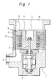
- a conventional turbomolecular pump which is generally denoted by the reference numeral 1 includes a motor 2, a motor shaft 3 for transmitting the rotational force derived from the motor 2, a rotor 4 secured to the motor shaft 3, a plurality of rotor blades 5 fixed to the rotor 4, a plurality of stator blades 6 each disposed between a pair of adjacent rotor blades 5, a spacer 7 having the stator blades 6 attached thereto, a casing 10 provided with a suction port 8 and an exhaust port 9, and a protective net 11 for protecting the rotor and stator blades 5 and 6.
- the motor 2 is driven to rotate the rotor blades 5 at high speed in a high-vacuum atmosphere sufficient to ensure that molecular flow is available, thereby sucking gas molecules from the suction port 8, compressing the gas at a high compression ratio and moving the gas toward the exhaust port 9, thus producing a high vacuum.
- the above-described conventional turbomolecular pump suffers, however, from the following problems.
- the gas exhausting performance of the pump depends on the molecular weight of a gas being handled by it. When a gas having a low molecular weight is being handled, the gas exhausting performance deteriorates to a considerable extent.
- Vm ⁇ (2KT/M) (wherein M is the molecular weight of the gas, K is Boltzmann's constant, and T is the absolute temperature of the gas).
- cryo-vacuum pump that employs a helium refrigerator and a heat exchanger which provides ultra-low temperatures of from about 15°K to about 20°K, the gas exhausting characteristics in regard to water vapor are improved and it is therefore possible to cope with the above-described problems to a certain extent.
- a cryo-vacuum pump involves the following problems:
- turbomolecular pump the operation of which is capable of effectively exhausting gases having low molecular weights, particularly water vapor, and the operation of which is easy to start and suspend, as well as being capable of operating on a continuous basis.
- the present invention provides a turbomolecular pump having a rotor provided with a plurality of rotor blades and a spacer provided with a plurality of stator blades so that gas molecules are sucked in from a suction port, compressed and discharged from an exhaust port, wherein the improvement comprises: a heat exchanger provided inside the suction port, the heat exchanger being connected to a refrigerator through a refrigerant pipe; and a gate valve provided on the upstream side of the suction port.
- the refrigerator preferably has the capability of supplying a refrigerant cooled to from about -100°C to about -190°C and it is preferable either to employ as the refrigerator one which is capable of defrosting or, if the refrigerator is not capable of defrosting, to further provide a heater at the suction port.
- the present invention provides a method of operating a turbomolecular pump comprising: an exhaust step in which a gate valve provided on the upstream side of a suction port is opened and, in this state, water vapor is freeze-trapped by a heat exchanger provided inside the suction port; and a regeneration step in which, with the gate valve closed, the water vapor freeze-trapped is thawed and released.
- the regeneration step preferably includes either the step of switching over the operating mode of a refrigerator from the refrigerating mode to the defrost mode or the step of effecting, with the refrigerating capacity of the refrigerator maintained or lowered, heating in excess of the refrigerating capacity by means of a heater which is provided at the suction port.
- the regeneration step may also be effected by just closing a gate valve and continuing the exhaust operation of a turbomolecular pump.
- the gate valve provided on the upstream side of the suction port is opened and the refrigerator is run in the refrigerating mode to deliver a refrigerant to the heat exchanger so as to cool it. Further, the rotor blades are rotated to suck a gas into the pump. At this time, water vapor contained in the gas is selectively freeze-trapped by the heat exchanger. As a result, the gas exhausting performance of the turbomolecular pump is improved and it is therefore possible to produce a high vacuum of good quality.
- the gas exhausting operation After the gas exhausting operation has been conducted for a predetermined period of time, it is necessary to carry out a regenerative operation in which water vapor which has been freeze-trapped on the heat exchanger is thawed and released. In such a regenerative operation, it is only necessary to heat the water vapor freeze-trapped on the heat exchanger with the gate valve closed.
- the heating may be effected by switching over the operating mode of the refrigerator from the refrigerating mode to the defrost mode to thereby conduct heating through the heat exchanger, or by maintaining or lowering the refrigerating capacity of the refrigerator and effecting, in this state, heating in excess of the refrigerating capacity by means of a heater provided at the suction port.
- the freeze-trapped water vapor sublimates by absorbing heat from either the heat exchanger or the heater and is then discharged from the exhaust port by the interaction between the rotor and stator blades. In this way, the regeneration step is carried out. Thus, the time required to switch over to the regeneration step and to complete the regeneration is reduced by a large margin.
- the regenerative operation may also be effected by just continuing the exhaust operation of the turbomolecular pump with the gate valve closed. In this case, the heating of the water vapor as stated above is not necessary.
- This regenerative operation can be conducted by the use of the gate valve cut-off time during normal operation of a turbomolecular pump in, for example, a semiconductor manufacturing process, and this makes it possible to run the turbomolecular pump on a continuous basis without requiring a specific time for regeneration.
- the present invention provides a turbomolecular pump which enables gases having low molecular weights, particularly water vapor, to be efficiently exhausted, while maintaining the advantages of the conventional turbomolecular pump, namely, that it is easy to start and suspend the operation of the system and also possible to run it on a continuous basis. It should be noted that the present invention enables selection of a desired configuration and heat-exchange area of the heat exchanger on the basis of the constituents of a gas to be exhausted and the exhaustion time.
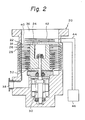
- FIG. 2 shows a first embodiment of the present inven thoughtion.
- a turbomolecular pump which is generally denoted by the reference numeral 20 has a rotor 24 provided with a plurality of rotor blades 22 and a spacer 28 having a plurality of stator blades 26 attached thereto, each stator blade 26 being disposed between a pair of adjacent rotor blades 22.
- the rotor 24 is secured to a motor shaft 32 of a motor 30.
- the spacer 28 is fixed within a casing 34.
- the casing 34 is provided with a suction port 36 and an exhaust port 38.
- a protective net 40 for protecting the rotor and stator blades 22 and 26 is provided on the downstream side of the suction port 36 (i.e., the side of the suction port 36 which is closer to the exhaust port 38 as viewed in the direction of the flow of gas) and at the upstream side of the rotor and stator blades 22 and 26.
- a gate valve (not shown) is disposed on the upstream side of the suction port 36.
- the turbomolecular pump 20 shown in Fig. 2 has a heat exchanger 42 which is provided at the suction port 36.
- the heat exchanger 42 is connected to a refrigerator 46 through a refrigerant pipe 44.
- the refrigerator 46 is of the type in which either a low-temperature refrigerant fluid or an ordinary-temperature refrigerant fluid (or hot gas) can be selectively supplied through the refrigerant pipe 44 by actuating a selector valve incorporated therein (not shown), thereby enabling the refrigerating mode and the defrost mode to be switched over from one to the other within a short time, as is disclosed, for example, in United States Patent No. 4,176,526.
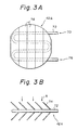
- the heat exchanger 42 shown in Fig. 2 may be arranged as shown in Figs. 3A to 5B.
- the heat exchanger 42A shown in Figs. 3A and 3B comprises a flat heat transfer coil 72 and a plurality of heat transfer plates 74 blazed on upper and lower sides of said heat transfer coil in spaced relationship to each other so that gas molecules sucked in from said suction port pass therebetween.
- the exchanger 42A is supplied with a cooled refrigerant through the refrigerant pipe 44 (see Fig. 2) from the refrigerator 46 (see Fig. 2).
- the refrigerant enters the heat exchanger 42A through a refrigerant inlet 70, cools the heat transfer coil 72 and heat transfer plates 74 and returns to the refrigerator 46 from a refrigerant outlet 76.
- a refrigerant inlet 70 cools the heat transfer coil 72 and heat transfer plates 74 and returns to the refrigerator 46 from a refrigerant outlet 76.
- the molecules are freeze-trapped with a predetermined probability.
- the arrow A shown in Fig. 3B indicates the flow of gas that is sucked into the turbomolecular pump 20.
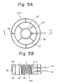
- the heat exchanger 42B that is shown in Figs. 4A and 4B, comprises a cylindrical heat transfer coil 72′, a cylindrical heat transfer member 74′ concentrically encircling said heat transfer coil, and a plurality of radial heat transfer plates 74 ⁇ blazed between said heat transfer coil 72′ and heat transfer member 74′.
- the heat transfer coil 72′, heat transfer member 74′ and heat transfer plates 74 ⁇ are disposed parallel to the flow of gas molecules sucked in from said suction port, minimizing the flow resistance.
- a cylindrical heat shield member 78 is concentrically attached by means of plates 79 to the outside of a heat exchanger 42C having the same arrangement as that shown in Figs. 4A and 4B and serves to minimize heat loss (absorption of heat) due to radiation heat transfer.
- the gate valve (not shown) provided on the upstream side of the suction port 36 is opened and the refrigerator 46 is run in the refrigerating mode to supply low-temperature refrigerant to the heat exchanger 42.
- the motor 30 is rotated to suck in a gas through the suction port 36. In consequence, water vapor contained in the gas is freeze-trapped by the heat exchanger 42. As a result, the gas exhausting efficiency of the turbomolecular pump shown in Fig. 2 increases, so it is possible to obtain a high vacuum of good quality.
- Gas molecules (hydrogen, helium, etc.) having low molecular weights, exclusive of water vapor, are not freeze-trapped, but the gas temperature lowers through collision or contact of these gas molecules with the heat exchanger 42, so that the blade speed ratio increases and thus the gas exhausting performance of the pump 20 is improved.
- Fig. 6 is a graph showing the saturated vapor pressure of water vapor, at -85°C the saturated vapor pressure of water vapor is 10 ⁇ 4 Torr (10 ⁇ 4 mmHg), and at -140°C, 10 ⁇ 10 Torr (10 ⁇ 10 mmHg).
- the strength of the resulting vacuum is increased by conducting the gas exhausting operation while freeze-trapping water vapor.
- the embodiment shown in Fig. 2 employs a refrigerant source that provide temperatures of from -100°C to -190°C.
- the gate valve (not shown in Fig. 2 but identical with the member denoted by reference numeral 90 in Fig. 7) which is disposed on the upstream side of the suction port 36 is closed and the refrigerator 46 is switched to the defrost mode, thereby supplying an ordinary-temperature refrigerant fluid or hot gas to the heat exchanger 42 so as to heat it.
- the water vapor freeze-trapped on the heat exchanger 42 sublimates by absorbing heat from the heat exchanger 42 and is then discharged by the interaction between the rotor blades 22 and the stator blades 26.
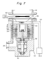
- FIG. 7 members which are the same as those shown in Fig. 2 are denoted by the same reference numerals.
- a heater 52 is provided at the suction port 36 in addition to the heat exchanger 42.
- the refrigerator 46A need not necessarily be capable of defrosting.
- the exhaust step is the same as that in the embodiment shown in Fig. 2, but in the regeneration step, with the refrigerating capacity of the refrigerator 46A maintained or lowered, heating is conducted in excess of the refrigerating capacity by means of the heater 52.
- the water vapor that has been freeze-trapped on the heat exchanger 42 is sublimated on being heated by the heater 52 and is discharged by the interaction between the rotor and stator blades 22 and 26.
- the reference numeral 90 shown in Fig. 7 denotes a gate valve, and 92 a vacuum vessel or a pipe which is connected thereto.
- the regenerative step may also be conducted by just closing the gate valve and continuing the exhaust operation of the turbomolecular pump.
- the vapor pressure in a space downstream of the suction port 36 i.e. a trap room
- the water vapor pressure in the trap room before closing the gate valve is 6 x 10 ⁇ 6 Torr (point A in Fig. 6).
- Such a regenerative operation does not need the switching over of the refrigerator 46A between the refrigerating mode and the defrost mode, as is needed in the first embodiment, or the heating of the heat exchanger 42, as is needed in the second embodiment. Thus there is no need for a specific time to be used solely for the regenerative step.
- the regenerative operation can be conducted by the use of the gate valve cut-off time during a normal driving process of a turbomolecular pump in, for example, a semiconductor manufacturing process.
- turbomolecular pump of the present invention it is possible according to the turbomolecular pump of the present invention to eliminate the problems caused by the existence of gas molecules having low molecular weights, particularly water vapor contained in the gas which is to be exhausted, and yet to enable the operation of the system to be readily started and suspended. Accordingly, it is possible to obtain a high vacuum of good quality within a short period of time.
- turbomolecular pump according to the present invention is provided with an independent heat exchanger not for the purpose of cooling a part of a constituent element of the pump, for example, the casing or stator blades, but for the purpose of freeze-trapping gas molecules. It is therefore possible to select a desired configuration and heating area of the heat exchanger on the basis of the constituents of the gas to be exhausted and the exhaustion time.
Landscapes
- Engineering & Computer Science (AREA)
- Mechanical Engineering (AREA)
- General Engineering & Computer Science (AREA)
- Non-Positive Displacement Air Blowers (AREA)
Applications Claiming Priority (3)
| Application Number | Priority Date | Filing Date | Title |
|---|---|---|---|
| JP5162388 | 1988-03-07 | ||
| JP51623/88 | 1988-03-07 | ||
| JP5162388 | 1988-03-07 |
Publications (3)
| Publication Number | Publication Date |
|---|---|
| EP0332107A1 true EP0332107A1 (de) | 1989-09-13 |
| EP0332107B1 EP0332107B1 (de) | 1992-07-08 |
| EP0332107B2 EP0332107B2 (de) | 2001-10-31 |
Family
ID=12891996
Family Applications (1)
| Application Number | Title | Priority Date | Filing Date |
|---|---|---|---|
| EP89103895A Expired - Lifetime EP0332107B2 (de) | 1988-03-07 | 1989-03-06 | Turbomolekularpumpe und deren Betriebsverfahren |
Country Status (4)
| Country | Link |
|---|---|
| US (1) | US4926648A (de) |
| EP (1) | EP0332107B2 (de) |
| KR (1) | KR0124416B1 (de) |
| DE (1) | DE68901986T3 (de) |
Cited By (17)
| Publication number | Priority date | Publication date | Assignee | Title |
|---|---|---|---|---|
| EP0397051A1 (de) * | 1989-05-09 | 1990-11-14 | Kabushiki Kaisha Toshiba | Evakuierungsvorrichtung und Evakuierungsverfahren |
| EP0610666A1 (de) * | 1993-01-11 | 1994-08-17 | Applied Materials, Inc. | Turbomolekularpumpe |
| US5483803A (en) * | 1993-06-16 | 1996-01-16 | Helix Technology Corporation | High conductance water pump |
| FR2723987A1 (fr) * | 1994-08-23 | 1996-03-01 | Commissariat Energie Atomique | Pompe a vide cryomecanique |
| EP0819856A1 (de) * | 1996-07-18 | 1998-01-21 | VARIAN S.p.A. | Vakuumpumpe |
| EP0893604A1 (de) * | 1997-07-25 | 1999-01-27 | Ebara Corporation | Turbomolekularpumpe |
| EP0898081A1 (de) * | 1997-08-15 | 1999-02-24 | Ebara Corporation | Turbomolekularpumpe |
| EP0898082A1 (de) * | 1997-08-15 | 1999-02-24 | Ebara Corporation | Turbomolekularpumpe |
| FR2776029A1 (fr) * | 1998-03-16 | 1999-09-17 | Alsthom Cge Alcatel | Pompe turbomoleculaire |
| USRE36610E (en) * | 1989-05-09 | 2000-03-14 | Kabushiki Kaisha Toshiba | Evacuation apparatus and evacuation method |
| KR20000017624A (ko) * | 1998-08-28 | 2000-03-25 | 다카키도시요시 | 진공펌프 및 진공장치 |
| EP1061262A3 (de) * | 1999-06-14 | 2002-03-06 | Ebara Corporation | Turbomolekularpumpe |
| EP1063456A3 (de) * | 1999-06-23 | 2002-08-07 | Mks Instruments, Inc. | Integrierte Turbopumpe und Steuerventilsystem |
| US6589009B1 (en) | 1997-06-27 | 2003-07-08 | Ebara Corporation | Turbo-molecular pump |
| WO2005093260A1 (en) * | 2004-03-26 | 2005-10-06 | The Boc Group Plc | Vacuum pump |
| WO2006095132A1 (en) * | 2005-03-07 | 2006-09-14 | Edwards Limited | Apparatus for inhibiting the propagation of a flame front |
| EP1669608A3 (de) * | 2004-11-24 | 2007-01-24 | Pfeiffer Vacuum GmbH | Vakuumpumpe |
Families Citing this family (22)
| Publication number | Priority date | Publication date | Assignee | Title |
|---|---|---|---|---|
| US6022195A (en) * | 1988-09-13 | 2000-02-08 | Helix Technology Corporation | Electronically controlled vacuum pump with control module |
| US6318093B2 (en) * | 1988-09-13 | 2001-11-20 | Helix Technology Corporation | Electronically controlled cryopump |
| US5443368A (en) * | 1993-07-16 | 1995-08-22 | Helix Technology Corporation | Turbomolecular pump with valves and integrated electronic controls |
| US5231839A (en) * | 1991-11-27 | 1993-08-03 | Ebara Technologies Incorporated | Methods and apparatus for cryogenic vacuum pumping with reduced contamination |
| JP3377224B2 (ja) * | 1992-03-31 | 2003-02-17 | 日本原子力研究所 | 真空ポンプの排気方法 |
| US5261244A (en) * | 1992-05-21 | 1993-11-16 | Helix Technology Corporation | Cryogenic waterpump |
| US5577883A (en) * | 1992-06-19 | 1996-11-26 | Leybold Aktiengesellschaft | Gas friction vacuum pump having a cooling system |
| WO1994007033A1 (en) * | 1992-09-23 | 1994-03-31 | United States Of America As Represented By The Secretary Of The Air Force | Turbo-molecular blower |
| US6902378B2 (en) * | 1993-07-16 | 2005-06-07 | Helix Technology Corporation | Electronically controlled vacuum pump |
| JP2719298B2 (ja) * | 1993-07-29 | 1998-02-25 | アプライド マテリアルズ インコーポレイテッド | 真空装置の冷却構造 |
| US5513499A (en) * | 1994-04-08 | 1996-05-07 | Ebara Technologies Incorporated | Method and apparatus for cryopump regeneration using turbomolecular pump |
| DE69528913T2 (de) * | 1994-04-28 | 2003-09-04 | Ebara Corp., Tokio/Tokyo | Kryopumpe |
| US6793466B2 (en) * | 2000-10-03 | 2004-09-21 | Ebara Corporation | Vacuum pump |
| JP2002155891A (ja) * | 2000-11-22 | 2002-05-31 | Seiko Instruments Inc | 真空ポンプ |
| JP4657463B2 (ja) * | 2001-02-01 | 2011-03-23 | エドワーズ株式会社 | 真空ポンプ |
| JP4250353B2 (ja) * | 2001-06-22 | 2009-04-08 | エドワーズ株式会社 | 真空ポンプ |
| JP5350598B2 (ja) * | 2007-03-28 | 2013-11-27 | 東京エレクトロン株式会社 | 排気ポンプ、連通管、排気システム及び基板処理装置 |
| JP6943629B2 (ja) * | 2017-05-30 | 2021-10-06 | エドワーズ株式会社 | 真空ポンプとその加熱装置 |
| CN108266382B (zh) * | 2017-12-04 | 2020-08-28 | 安徽颐博水泵科技有限公司 | 一种卧式多级泵 |
| GB2575450B (en) * | 2018-07-09 | 2022-01-26 | Edwards Ltd | A variable inlet conductance vacuum pump, vacuum pump arrangement and method |
| JP2022135716A (ja) * | 2021-03-05 | 2022-09-15 | エドワーズ株式会社 | 真空ポンプ、及び、真空排気装置 |
| CN117846987B (zh) * | 2024-01-05 | 2024-12-03 | 北京中科科仪股份有限公司 | 一种复合冷凝分子筛吸附泵 |
Citations (2)
| Publication number | Priority date | Publication date | Assignee | Title |
|---|---|---|---|---|
| US3625019A (en) * | 1969-10-27 | 1971-12-07 | Sargent Welch Scientific Co | Vacuum pump with demountable cold trap and getter pump |
| DE7312037U (de) * | 1973-03-30 | 1973-06-20 | Leybold Heraeus Gmbh & Co Kg | Pumpenkombination |
Family Cites Families (13)
| Publication number | Priority date | Publication date | Assignee | Title |
|---|---|---|---|---|
| DE7312372U (de) * | Gesellschaft Fuer Kernforschung Mbh, 7500 Karlsruhe | |||
| US3149775A (en) * | 1961-12-13 | 1964-09-22 | Gen Electric | Vacuum system |
| FR1466322A (fr) * | 1965-09-08 | 1967-01-20 | Radiotechnique | Dispositif permettant d'améliorer le vide d'une enceinte |
| FR1587077A (de) * | 1968-08-01 | 1970-03-13 | ||
| US3597267A (en) * | 1969-02-26 | 1971-08-03 | Allied Res Prod Inc | Bath and process for chemical metal plating |
| FR2114039A5 (de) * | 1970-11-13 | 1972-06-30 | Air Liquide | |
| US4176526A (en) * | 1977-05-24 | 1979-12-04 | Polycold Systems, Inc. | Refrigeration system having quick defrost and re-cool |
| JPS57212395A (en) * | 1981-06-24 | 1982-12-27 | Hitachi Ltd | Molecular pump |
| US4438632A (en) * | 1982-07-06 | 1984-03-27 | Helix Technology Corporation | Means for periodic desorption of a cryopump |
| JPS5990784A (ja) * | 1982-11-12 | 1984-05-25 | Shimadzu Corp | 真空排気装置 |
| US4535597A (en) * | 1984-01-25 | 1985-08-20 | Marin Tek, Inc. | Fast cycle water vapor cryopump |
| JPS60161702A (ja) * | 1984-01-27 | 1985-08-23 | Seiko Instr & Electronics Ltd | 真空用冷却トラツプ |
| JPS62168994A (ja) * | 1985-12-26 | 1987-07-25 | Morihiko Kimata | 高真空排気装置 |
-
1989
- 1989-03-03 US US07/318,206 patent/US4926648A/en not_active Expired - Lifetime
- 1989-03-06 DE DE68901986T patent/DE68901986T3/de not_active Expired - Fee Related
- 1989-03-06 EP EP89103895A patent/EP0332107B2/de not_active Expired - Lifetime
- 1989-03-07 KR KR1019890002791A patent/KR0124416B1/ko not_active Expired - Fee Related
Patent Citations (2)
| Publication number | Priority date | Publication date | Assignee | Title |
|---|---|---|---|---|
| US3625019A (en) * | 1969-10-27 | 1971-12-07 | Sargent Welch Scientific Co | Vacuum pump with demountable cold trap and getter pump |
| DE7312037U (de) * | 1973-03-30 | 1973-06-20 | Leybold Heraeus Gmbh & Co Kg | Pumpenkombination |
Non-Patent Citations (2)
| Title |
|---|
| PATENT ABSTRACTS OF JAPAN, vol. 8, no. 201 (M-325)[1639], 14th September 1984; & JP-A-59 90 784 (SHIMAZU SEISAKUSHO K.K.) 25-05-1984 * |
| SOVIET INVENTIONS ILLUSTRATED SECTION P/Q, week E39, 10th November 1982, class Q, no. M8488E/39, Derwent Publications Ltd, London, GB; & SU-A-881 372 (TUZANKIN YU M) 11-04-1980 * |
Cited By (24)
| Publication number | Priority date | Publication date | Assignee | Title |
|---|---|---|---|---|
| USRE36610E (en) * | 1989-05-09 | 2000-03-14 | Kabushiki Kaisha Toshiba | Evacuation apparatus and evacuation method |
| US5062271A (en) * | 1989-05-09 | 1991-11-05 | Kabushiki Kaisha Toshiba | Evacuation apparatus and evacuation method |
| EP0397051A1 (de) * | 1989-05-09 | 1990-11-14 | Kabushiki Kaisha Toshiba | Evakuierungsvorrichtung und Evakuierungsverfahren |
| EP0610666A1 (de) * | 1993-01-11 | 1994-08-17 | Applied Materials, Inc. | Turbomolekularpumpe |
| US5483803A (en) * | 1993-06-16 | 1996-01-16 | Helix Technology Corporation | High conductance water pump |
| FR2723987A1 (fr) * | 1994-08-23 | 1996-03-01 | Commissariat Energie Atomique | Pompe a vide cryomecanique |
| EP0819856A1 (de) * | 1996-07-18 | 1998-01-21 | VARIAN S.p.A. | Vakuumpumpe |
| US6589009B1 (en) | 1997-06-27 | 2003-07-08 | Ebara Corporation | Turbo-molecular pump |
| EP0893604A1 (de) * | 1997-07-25 | 1999-01-27 | Ebara Corporation | Turbomolekularpumpe |
| EP0898081A1 (de) * | 1997-08-15 | 1999-02-24 | Ebara Corporation | Turbomolekularpumpe |
| EP0898082A1 (de) * | 1997-08-15 | 1999-02-24 | Ebara Corporation | Turbomolekularpumpe |
| US6062810A (en) * | 1997-08-15 | 2000-05-16 | Ebara Corporation | Turbomolecular pump |
| US6220831B1 (en) | 1997-08-15 | 2001-04-24 | Ebara Corporation | Turbomolecular pump |
| FR2776029A1 (fr) * | 1998-03-16 | 1999-09-17 | Alsthom Cge Alcatel | Pompe turbomoleculaire |
| EP0943807A1 (de) * | 1998-03-16 | 1999-09-22 | Alcatel | Turbomolekularpumpe |
| US6186749B1 (en) | 1998-03-16 | 2001-02-13 | Alcatel | Molecular drag pump |
| KR20000017624A (ko) * | 1998-08-28 | 2000-03-25 | 다카키도시요시 | 진공펌프 및 진공장치 |
| EP0982500A3 (de) * | 1998-08-28 | 2001-05-30 | Seiko Seiki Kabushiki Kaisha | Vakuumpumpe und Vakuumanlage |
| EP1061262A3 (de) * | 1999-06-14 | 2002-03-06 | Ebara Corporation | Turbomolekularpumpe |
| EP1063456A3 (de) * | 1999-06-23 | 2002-08-07 | Mks Instruments, Inc. | Integrierte Turbopumpe und Steuerventilsystem |
| WO2005093260A1 (en) * | 2004-03-26 | 2005-10-06 | The Boc Group Plc | Vacuum pump |
| EP1669608A3 (de) * | 2004-11-24 | 2007-01-24 | Pfeiffer Vacuum GmbH | Vakuumpumpe |
| WO2006095132A1 (en) * | 2005-03-07 | 2006-09-14 | Edwards Limited | Apparatus for inhibiting the propagation of a flame front |
| KR101244492B1 (ko) * | 2005-03-07 | 2013-03-18 | 에드워즈 리미티드 | 화염 전면의 전파 방지 장치 및 방법 |
Also Published As
| Publication number | Publication date |
|---|---|
| EP0332107B2 (de) | 2001-10-31 |
| KR890014975A (ko) | 1989-10-25 |
| KR0124416B1 (ko) | 1997-12-18 |
| US4926648A (en) | 1990-05-22 |
| DE68901986D1 (de) | 1992-08-13 |
| DE68901986T3 (de) | 2002-06-27 |
| EP0332107B1 (de) | 1992-07-08 |
| DE68901986T2 (de) | 1993-03-04 |
Similar Documents
| Publication | Publication Date | Title |
|---|---|---|
| EP0332107B1 (de) | Turbomolekularpumpe und deren Betriebsverfahren | |
| EP0397051B1 (de) | Evakuierungsvorrichtung und Evakuierungsverfahren | |
| US4679401A (en) | Temperature control of cryogenic systems | |
| EP0207230B1 (de) | Kryopumpe für Wasserdampf mit schnell umschaltbarem Kreislauf | |
| US4718240A (en) | Cryopump regeneration method and apparatus | |
| CN111542698B (zh) | 具有增强型正面阵列的低温泵 | |
| US5345787A (en) | Miniature cryosorption vacuum pump | |
| EP0610666B1 (de) | Turbomolekularpumpe | |
| EP0506133B1 (de) | Kryopumpe | |
| WO1999009317A1 (en) | Cold trap with integral gate valve | |
| USRE36610E (en) | Evacuation apparatus and evacuation method | |
| JP2763524B2 (ja) | 二次ポンプ装置 | |
| TW202235748A (zh) | 低溫泵 | |
| JP2503267B2 (ja) | タ―ボ分子ポンプおよびその運転方法 | |
| JP4504476B2 (ja) | 分子ポンプ | |
| EP0214277B1 (de) | Verfahren und vorrichtung zum regenerieren einer kryopumpe | |
| JP2503267C (de) | ||
| JP4304450B2 (ja) | 真空排気装置 | |
| JPH0774635B2 (ja) | 真空排気装置 | |
| JP2674591B2 (ja) | 真空処理装置の運転方法 | |
| Hands | Cryopumping | |
| JP2790936B2 (ja) | ターボ分子ポンプによる排気方法及び装置 | |
| JPH02294575A (ja) | 真空排気装置及びその再生方法 | |
| WO2024262646A1 (ja) | 二酸化炭素の回収方法および二酸化炭素の回収装置 | |
| Danielson | Matching Cryopumping Techniques to Application |
Legal Events
| Date | Code | Title | Description |
|---|---|---|---|
| PUAI | Public reference made under article 153(3) epc to a published international application that has entered the european phase |
Free format text: ORIGINAL CODE: 0009012 |
|
| AK | Designated contracting states |
Kind code of ref document: A1 Designated state(s): DE FR GB |
|
| 17P | Request for examination filed |
Effective date: 19900126 |
|
| 17Q | First examination report despatched |
Effective date: 19901002 |
|
| GRAA | (expected) grant |
Free format text: ORIGINAL CODE: 0009210 |
|
| AK | Designated contracting states |
Kind code of ref document: B1 Designated state(s): DE FR GB |
|
| REF | Corresponds to: |
Ref document number: 68901986 Country of ref document: DE Date of ref document: 19920813 |
|
| ET | Fr: translation filed | ||
| PLBI | Opposition filed |
Free format text: ORIGINAL CODE: 0009260 |
|
| 26 | Opposition filed |
Opponent name: LEYBOLD AKTIENGESELLSCHAFT Effective date: 19930406 |
|
| APAC | Appeal dossier modified |
Free format text: ORIGINAL CODE: EPIDOS NOAPO |
|
| APAA | Appeal reference recorded |
Free format text: ORIGINAL CODE: EPIDOS REFN |
|
| APAC | Appeal dossier modified |
Free format text: ORIGINAL CODE: EPIDOS NOAPO |
|
| PLAW | Interlocutory decision in opposition |
Free format text: ORIGINAL CODE: EPIDOS IDOP |
|
| PUAH | Patent maintained in amended form |
Free format text: ORIGINAL CODE: 0009272 |
|
| STAA | Information on the status of an ep patent application or granted ep patent |
Free format text: STATUS: PATENT MAINTAINED AS AMENDED |
|
| 27A | Patent maintained in amended form |
Effective date: 20011031 |
|
| AK | Designated contracting states |
Kind code of ref document: B2 Designated state(s): DE FR GB |
|
| REG | Reference to a national code |
Ref country code: GB Ref legal event code: IF02 |
|
| ET3 | Fr: translation filed ** decision concerning opposition | ||
| PGFP | Annual fee paid to national office [announced via postgrant information from national office to epo] |
Ref country code: GB Payment date: 20050302 Year of fee payment: 17 |
|
| PGFP | Annual fee paid to national office [announced via postgrant information from national office to epo] |
Ref country code: DE Payment date: 20050304 Year of fee payment: 17 |
|
| PGFP | Annual fee paid to national office [announced via postgrant information from national office to epo] |
Ref country code: FR Payment date: 20050308 Year of fee payment: 17 |
|
| APAH | Appeal reference modified |
Free format text: ORIGINAL CODE: EPIDOSCREFNO |
|
| PG25 | Lapsed in a contracting state [announced via postgrant information from national office to epo] |
Ref country code: GB Free format text: LAPSE BECAUSE OF NON-PAYMENT OF DUE FEES Effective date: 20060306 |
|
| PG25 | Lapsed in a contracting state [announced via postgrant information from national office to epo] |
Ref country code: DE Free format text: LAPSE BECAUSE OF NON-PAYMENT OF DUE FEES Effective date: 20061003 |
|
| GBPC | Gb: european patent ceased through non-payment of renewal fee |
Effective date: 20060306 |
|
| REG | Reference to a national code |
Ref country code: FR Ref legal event code: ST Effective date: 20061130 |
|
| PG25 | Lapsed in a contracting state [announced via postgrant information from national office to epo] |
Ref country code: FR Free format text: LAPSE BECAUSE OF NON-PAYMENT OF DUE FEES Effective date: 20060331 |