EP0332111A1 - Appareil à couper - Google Patents
Appareil à couper Download PDFInfo
- Publication number
- EP0332111A1 EP0332111A1 EP19890103903 EP89103903A EP0332111A1 EP 0332111 A1 EP0332111 A1 EP 0332111A1 EP 19890103903 EP19890103903 EP 19890103903 EP 89103903 A EP89103903 A EP 89103903A EP 0332111 A1 EP0332111 A1 EP 0332111A1
- Authority
- EP
- European Patent Office
- Prior art keywords
- support
- chainsaw
- frame
- pivoted
- pedal
- Prior art date
- Legal status (The legal status is an assumption and is not a legal conclusion. Google has not performed a legal analysis and makes no representation as to the accuracy of the status listed.)
- Withdrawn
Links
- 238000005520 cutting process Methods 0.000 title claims abstract description 28
- 230000008878 coupling Effects 0.000 claims description 6
- 238000010168 coupling process Methods 0.000 claims description 6
- 238000005859 coupling reaction Methods 0.000 claims description 6
- 230000000284 resting effect Effects 0.000 claims description 6
- 229910052751 metal Inorganic materials 0.000 claims description 5
- 230000001133 acceleration Effects 0.000 claims 1
- 239000000463 material Substances 0.000 description 3
- 239000002023 wood Substances 0.000 description 3
- 239000000446 fuel Substances 0.000 description 2
- 239000002184 metal Substances 0.000 description 2
- 101100008047 Caenorhabditis elegans cut-3 gene Proteins 0.000 description 1
- 230000002452 interceptive effect Effects 0.000 description 1
- 230000000670 limiting effect Effects 0.000 description 1
- 230000004048 modification Effects 0.000 description 1
- 238000012986 modification Methods 0.000 description 1
- 230000010355 oscillation Effects 0.000 description 1
- 239000002699 waste material Substances 0.000 description 1
Images




Classifications
-
- B—PERFORMING OPERATIONS; TRANSPORTING
- B27—WORKING OR PRESERVING WOOD OR SIMILAR MATERIAL; NAILING OR STAPLING MACHINES IN GENERAL
- B27B—SAWS FOR WOOD OR SIMILAR MATERIAL; COMPONENTS OR ACCESSORIES THEREFOR
- B27B17/00—Chain saws; Equipment therefor
- B27B17/0041—Saw benches or saw bucks
- B27B17/0058—Saw benches or saw bucks with the saw being pivotally mounted
Definitions
- the present invention relates to a cutting apparatus particularly usable for wood bundles, tree trunks or logs, metal elements such as pipes, plates, profiled elements, slab-like elements etc.
- Portable chainsaws are currently used to cut tree trunks or logs; such chainsaws comprise a box like body which is fitted with grip means, contains actuation means and has a cutting blade which extends from said body.
- Such chainsaws are characterized by considerable discomfort in use, especially for cutting logs resting on the ground.
- the log cutting operation generally requires two people, one for cutting and one for securing the log during the operation.
- Bench-mounted circular saws or bench-mounted band saws are furthermore known which allow a certain increase in the speed of the cutting operation, but they are affected by the disadvantage that they are heavy and bulky and can be installed only inside carpenter's shops or workshops and cannot therefore be moved, for example, to a wood-shed.
- the aim of the present invention is to solve the disadvantages described above in the known art by providing a cutting apparatus on which any kind of known portable chainsaw can be coupled, said apparatus allowing comfort in operation for its operator and providing a certain repeatability in its operations, with consequent time saving.
- an important object is to provide an apparatus which requires only one person for the cutting operations.
- Another important object is to provide a cutting apparatus the use whereof eliminates the danger due to breakages of the cutting elements which normally occur when portable chainsaws are used on the ground.
- Still another object is to provide an apparatus which is suitable tor cutting wood, metal pipes or profiled elements and slab materials.
- Yet another object is to provide an apparatus which reduces the consumption of the fuel used to operate the chainsaw.
- a further object is to provide an apparatus which is safe for the operator in use.
- Not least object is to provide a cutting apparatus executable at low cost with easily commercially available elements.
- a cutting apparatus characterized in that it comprises a frame having inclined-plane resting means for the element to be cut, a support adapted to be rigidly coupled with a chainsaw and being pivoted to said frame, actuating means for causing movement of said support, thereby causing the chainsaw blade to interact with an element to be cut.
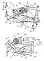
- the apparatus comprises, in a first embodiment, a frame 1 composed of rod-like metal elements welded to one another to form a substantially parallelepipedal bench-like structure.
- a rest support 2 for example for a log to be cut 3, is arranged above said frame 1 in a forward longitudinal position and has an L-shaped cross section which is slightly inclined with respect to a horizontal plane and is preferably obtained from folded sheet metal with panels made of wood or other suitable material rigidly upwardly coupled to said support.
- a support 5 for a known type of chainsaw 6 is pivoted to a pin 4 in a rearward longitudinal position above said frame 1; said chainsaw can be fixed to said support with its motor body 7 by means of known couplings, so that the cutting blade 8 can oscillate on a vertical plane transversely to said support 2 without interfering therewith by virtue of a gap in the resting table of the log 3.
- a grip handle 12 is pivoted to the element 9 above said lamina 10 by means of a pin 11 and extends on the opposite side of said lamina 10 with respect to the cutting tool 8; a stop element 13 for the log 3 to be cut is downwardly rigidly coupled to said handle 12.
- a lever element 15 is pivoted to a pin 14 in a downward longitudinal position at the rear portion of said frame 1, extends up to the front portion of said frame 1 and ends with an actuation pedal 16.
- Said lever element 15 is rigidly associated, in a middle position, with the lower ends of a vertical traction spring 17 which has its upper end rigidly associated with said frame 1 and is adapted to ensure an elastic return of the lever 15 after a pressure has been exerted on the pedal 16 with the foot.
- Said actuation pedal 16 is rigidly coupled to said support 5, and the ends of a rod-like connecting element 18 are hinged therebetween so that a downward oscillation of the lever element 15 correspondingly lowers the support 5.
- a lever system 19 is rigidly coupled in a middle position of said support 5 on the side corresponding to the region of the accelerator of the chainsaw 6, and its fulcrum 20 coincides with the rotational fulcrum of said accelerator; said lever system co-operates with an element 21 rigidly coupled to the rod-like element 9 so that the motor of the chainsaw 6 accelerates when the pedal 16 is lowered.
- a cable 22 is rigidly circumferentially associated with said pin 11 and is slidable inside a sheath 23; said cable is connected to a retractable pin 24 for securing said pedal 16, and the lowering of said grip handle 12 pulls the cable and therefore disengages the pin 24 of the pedal 16.
- a counterweight 25 rigidly associated with the support 5 and adapted to facilitate manual movements may be provided.
- the operation of the above described first embodiment of the apparatus according to the invention comprises the loading of the log 3 on the support 2 after starting the chainsaw and the gripping of the handle 12 with both hands, pressing on the log 3 with the stop element 13.
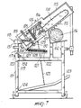
- the apparatus comprises, in a further embodiment thereof, a frame now indicated by the reference numeral 101, above which a support 102 for resting the logs to be cut is arranged in a frontward longitudinal position.
- a support 104 for fixing a chainsaw 105 is furthermore pivoted to a pin 103 above the frame 101 in a rearward longitudinal position; said chainsaw is fixed by means of a quick coupling bracket system generally indicated by 106.
- the quick coupling bracket system 106 comprises a pair of hexagonal nuts 107 screwed on two complementarily threaded pivots 108 which protrude in a parallel manner from the chainsaw 105 in a horizontal arrangement.
- Said hexagonal nuts 107 have, in their middle region, a machined cylindrical shape 109 enclosed between an upper bracket 110 and a lower bracket 111 rigidly associated with the support 104; the upper bracket and the lower bracket are mutually coupled by a fixing screw 112.
- a housing 113 is upwardly fixed to said articulation pivot 103 independently from said chainsaw 105 and houses the blade 114 of the chainsaw, leaving only its lower portion free; said housing has a lower set of teeth 115 adapted to lock the element to be cut, now indicated by the reference numeral 116, spacing the blade 114 by such a distance as to allow the startup of the motor of the chainsaw 105 so that it reaches its normal rpm when cutting starts.
- Said pin 103 is pivoted on a bracket 117 which is in turn rotatably associated with said frame 101 by means of another hinge pin 118 which is arranged orthogonally to said pivot 103 and allows to rotate the chainsaw 105 for refuelling.
- a bracket 119 with a locking screw 120 normally keeps said bracket 117 in its working position.
- a tab 121 extends substantially horizontally from the bracket 117, and a spring 122 is rigidly coupled between the end of said tab and said support 104; said spring is adapted to hinder the clockwise rotation of said support, actuated by a lever pedal 123 downwardly pivoted to the frame 101 by means of a pin 124, and said pedal 123 is connected to the support 104 by means of a chain 125 or by means of a rod.
- Another spring 126 is fixed between said support 104 and said housing 113 and keeps them substantially parallel until the blade interacts with the element to be cut.
- a support member 128 extends orthogonally from said support 104 and is fixed thereto by a screw 127; a pivot 129 is articulated at the upper end of said support member 128, and said pivot supports a bracket 130 on one side and, on the other side, the end of a spring 131 fixed on the bracket 119 proximate to the pin 103.
- the rotation of the bracket 130 exerts a pressure on the accelerator 132 of the chainsaw 105.
- Another support member 133 extends orthogonally from said housing 113 and is rigidly coupled therewith by means of a screw 134; said support member is adapted to stop the rotation of said bracket 130 in the direction of deceleration at the required intensity of the tension of the spring 131.
- this second embodiment of the apparatus according to the invention is similar to the preceding one, as it is sufficient to place the piece to be cut on the support 102 and to lower the support 104 and the associated chainsaw 105 by means of the pedal 123.
- the apparatus returns to its original position by releasing the pedal.
- the apparatus allows an adequate repeatability of the cutting operation so as to reduce work times.
- the apparatus according to the invention is suitable in both illustrated embodiments for any kind of chainsaw currently commercially available, whether electric or mixed-fuel powered.
Landscapes
- Life Sciences & Earth Sciences (AREA)
- Engineering & Computer Science (AREA)
- Mechanical Engineering (AREA)
- Wood Science & Technology (AREA)
- Forests & Forestry (AREA)
- Sawing (AREA)
Applications Claiming Priority (4)
| Application Number | Priority Date | Filing Date | Title |
|---|---|---|---|
| IT4155288 | 1988-03-11 | ||
| IT41552/88A IT1220660B (it) | 1988-03-11 | 1988-03-11 | Attrezzatura di taglio |
| IT8561488 | 1988-07-13 | ||
| IT8885614A IT1225578B (it) | 1988-07-13 | 1988-07-13 | Attrezzatura di taglio. |
Publications (1)
| Publication Number | Publication Date |
|---|---|
| EP0332111A1 true EP0332111A1 (fr) | 1989-09-13 |
Family
ID=26329121
Family Applications (1)
| Application Number | Title | Priority Date | Filing Date |
|---|---|---|---|
| EP19890103903 Withdrawn EP0332111A1 (fr) | 1988-03-11 | 1989-03-06 | Appareil à couper |
Country Status (1)
| Country | Link |
|---|---|
| EP (1) | EP0332111A1 (fr) |
Cited By (3)
| Publication number | Priority date | Publication date | Assignee | Title |
|---|---|---|---|---|
| DE9416499U1 (de) * | 1994-10-13 | 1995-01-05 | Hopfner, Andreas, 87669 Rieden | Motorsägestation |
| DE10224277A1 (de) * | 2001-10-19 | 2003-04-30 | Rupert Hager | Allgäuer Sägebock |
| GR1010350B (el) * | 2021-06-14 | 2022-12-07 | Γεωργιος Μιχαηλ Αποστολακης | Κατασκευη τετραχρονου αλυσοπριονου σε τροχηλατη βαση για κοπη καυσοξυλων |
Citations (4)
| Publication number | Priority date | Publication date | Assignee | Title |
|---|---|---|---|---|
| DE3105416A1 (de) * | 1981-02-14 | 1982-09-02 | Mafell Maschinenfabrik Rudolf Mey GmbH & Co KG, 7238 Oberndorf | "kettensaege" |
| DE3111641A1 (de) * | 1981-03-25 | 1982-11-04 | Hermann 8831 Bergen Horndasch | Tischkettensaege zum brennholzschneiden |
| US4538494A (en) * | 1982-11-29 | 1985-09-03 | Sandvik Ab | Means for actuating the throttle of a pivotably mounted chain saw |
| US4606252A (en) * | 1983-05-20 | 1986-08-19 | Terry Lahti | Chain saw wood cutting apparatus |
-
1989
- 1989-03-06 EP EP19890103903 patent/EP0332111A1/fr not_active Withdrawn
Patent Citations (4)
| Publication number | Priority date | Publication date | Assignee | Title |
|---|---|---|---|---|
| DE3105416A1 (de) * | 1981-02-14 | 1982-09-02 | Mafell Maschinenfabrik Rudolf Mey GmbH & Co KG, 7238 Oberndorf | "kettensaege" |
| DE3111641A1 (de) * | 1981-03-25 | 1982-11-04 | Hermann 8831 Bergen Horndasch | Tischkettensaege zum brennholzschneiden |
| US4538494A (en) * | 1982-11-29 | 1985-09-03 | Sandvik Ab | Means for actuating the throttle of a pivotably mounted chain saw |
| US4606252A (en) * | 1983-05-20 | 1986-08-19 | Terry Lahti | Chain saw wood cutting apparatus |
Cited By (3)
| Publication number | Priority date | Publication date | Assignee | Title |
|---|---|---|---|---|
| DE9416499U1 (de) * | 1994-10-13 | 1995-01-05 | Hopfner, Andreas, 87669 Rieden | Motorsägestation |
| DE10224277A1 (de) * | 2001-10-19 | 2003-04-30 | Rupert Hager | Allgäuer Sägebock |
| GR1010350B (el) * | 2021-06-14 | 2022-12-07 | Γεωργιος Μιχαηλ Αποστολακης | Κατασκευη τετραχρονου αλυσοπριονου σε τροχηλατη βαση για κοπη καυσοξυλων |
Similar Documents
| Publication | Publication Date | Title |
|---|---|---|
| US4188935A (en) | Roller handle for saw | |
| US4002094A (en) | Metal saw | |
| US1932511A (en) | Motor driven hand tool | |
| US1806528A (en) | Portable power-driven saw | |
| US2851067A (en) | Chain saw table | |
| CA1221004A (fr) | Accessoire pour scie a chaine | |
| US2716402A (en) | Masonry cutting machine | |
| US3433277A (en) | Foldable sawbuck | |
| US3051203A (en) | Lumber saw attachment for chain saws | |
| US3134409A (en) | Attachment for chain saws | |
| US4606252A (en) | Chain saw wood cutting apparatus | |
| US4553463A (en) | Portable wood cutting device | |
| US2600279A (en) | Portable power-driven planer | |
| CA1152868A (fr) | Scie a chaine et etabli connexe | |
| US5850696A (en) | Chain saw guard | |
| US4528881A (en) | Biased power feed device having means to reduce bias during adjustment | |
| US2463860A (en) | Mount for portable chain saws | |
| US2535491A (en) | Stroke saw | |
| CN2191073Y (zh) | 手提电圆锯 | |
| US2771105A (en) | Power driven hand tools | |
| US4573385A (en) | Chain saw cutting table | |
| US5484003A (en) | Chop saw table | |
| CN117817767A (zh) | 一种切割偏移自提醒式电圆锯 | |
| US2399541A (en) | Saw | |
| US4594920A (en) | Grinding machine for grinding cutter in cutter links |
Legal Events
| Date | Code | Title | Description |
|---|---|---|---|
| PUAI | Public reference made under article 153(3) epc to a published international application that has entered the european phase |
Free format text: ORIGINAL CODE: 0009012 |
|
| AK | Designated contracting states |
Kind code of ref document: A1 Designated state(s): DE ES FR GB IT |
|
| 17P | Request for examination filed |
Effective date: 19891025 |
|
| 17Q | First examination report despatched |
Effective date: 19910926 |
|
| STAA | Information on the status of an ep patent application or granted ep patent |
Free format text: STATUS: THE APPLICATION IS DEEMED TO BE WITHDRAWN |
|
| 18D | Application deemed to be withdrawn |
Effective date: 19920210 |