EP0332186A2 - Stirnwand aus formbarem Material für eine Wickelrolle - Google Patents
Stirnwand aus formbarem Material für eine Wickelrolle Download PDFInfo
- Publication number
- EP0332186A2 EP0332186A2 EP89104178A EP89104178A EP0332186A2 EP 0332186 A2 EP0332186 A2 EP 0332186A2 EP 89104178 A EP89104178 A EP 89104178A EP 89104178 A EP89104178 A EP 89104178A EP 0332186 A2 EP0332186 A2 EP 0332186A2
- Authority
- EP
- European Patent Office
- Prior art keywords
- stacking
- cams
- end wall
- plate
- pockets
- Prior art date
- Legal status (The legal status is an assumption and is not a legal conclusion. Google has not performed a legal analysis and makes no representation as to the accuracy of the status listed.)
- Granted
Links
- 239000000463 material Substances 0.000 title claims description 8
- 238000003780 insertion Methods 0.000 claims abstract description 18
- 230000037431 insertion Effects 0.000 claims abstract description 18
- 230000000295 complement effect Effects 0.000 claims abstract description 8
- 238000004804 winding Methods 0.000 claims description 34
- 238000004806 packaging method and process Methods 0.000 description 6
- 239000004033 plastic Substances 0.000 description 5
- 238000001746 injection moulding Methods 0.000 description 2
- 239000002184 metal Substances 0.000 description 2
- 238000006073 displacement reaction Methods 0.000 description 1
- 239000002985 plastic film Substances 0.000 description 1
- 229920006255 plastic film Polymers 0.000 description 1
- 239000011120 plywood Substances 0.000 description 1
- 238000004064 recycling Methods 0.000 description 1
- 239000012815 thermoplastic material Substances 0.000 description 1
- 239000002023 wood Substances 0.000 description 1
Images

Classifications
-
- B—PERFORMING OPERATIONS; TRANSPORTING
- B65—CONVEYING; PACKING; STORING; HANDLING THIN OR FILAMENTARY MATERIAL
- B65D—CONTAINERS FOR STORAGE OR TRANSPORT OF ARTICLES OR MATERIALS, e.g. BAGS, BARRELS, BOTTLES, BOXES, CANS, CARTONS, CRATES, DRUMS, JARS, TANKS, HOPPERS, FORWARDING CONTAINERS; ACCESSORIES, CLOSURES, OR FITTINGS THEREFOR; PACKAGING ELEMENTS; PACKAGES
- B65D59/00—Plugs, sleeves, caps, or like rigid or semi-rigid elements for protecting parts of articles or for bundling articles, e.g. protectors for screw-threads, end caps for tubes or for bundling rod-shaped articles
-
- B—PERFORMING OPERATIONS; TRANSPORTING
- B65—CONVEYING; PACKING; STORING; HANDLING THIN OR FILAMENTARY MATERIAL
- B65D—CONTAINERS FOR STORAGE OR TRANSPORT OF ARTICLES OR MATERIALS, e.g. BAGS, BARRELS, BOTTLES, BOXES, CANS, CARTONS, CRATES, DRUMS, JARS, TANKS, HOPPERS, FORWARDING CONTAINERS; ACCESSORIES, CLOSURES, OR FITTINGS THEREFOR; PACKAGING ELEMENTS; PACKAGES
- B65D85/00—Containers, packaging elements or packages, specially adapted for particular articles or materials
- B65D85/67—Containers, packaging elements or packages, specially adapted for particular articles or materials for web or tape-like material
- B65D85/671—Containers, packaging elements or packages, specially adapted for particular articles or materials for web or tape-like material wound in flat spiral form
- B65D85/672—Containers, packaging elements or packages, specially adapted for particular articles or materials for web or tape-like material wound in flat spiral form on cores
-
- Y—GENERAL TAGGING OF NEW TECHNOLOGICAL DEVELOPMENTS; GENERAL TAGGING OF CROSS-SECTIONAL TECHNOLOGIES SPANNING OVER SEVERAL SECTIONS OF THE IPC; TECHNICAL SUBJECTS COVERED BY FORMER USPC CROSS-REFERENCE ART COLLECTIONS [XRACs] AND DIGESTS
- Y10—TECHNICAL SUBJECTS COVERED BY FORMER USPC
- Y10S—TECHNICAL SUBJECTS COVERED BY FORMER USPC CROSS-REFERENCE ART COLLECTIONS [XRACs] AND DIGESTS
- Y10S292/00—Closure fasteners
- Y10S292/38—Plastic latch parts
Definitions
- the invention relates to an end wall made of moldable material for a winding roll, with a rectangular, in particular square, rounded corner surfaces having plate, the front of the winding roll facing forms a smooth, flat surface and the outside facing away from the winding roll stiffened by radial and annular ribs is, with a central insertion pin and locking cams on the front of the plate.
- Such a one-piece end wall made of plastic or another mouldable material for packaging winding material wound on winding tubes, for example plastic films, forms, together with the second corresponding end wall, a dimensionally stable overall packaging of a winding roll.
- the remaining packaging is generally constructed in such a way that additional parts for central fixing of the winding roll are inserted into a box made of wood or corrugated cardboard.
- additional parts include wooden boards with attached hubs, perforated discs made of plywood, hardboard, gray cardboard with inserted centering bushes made of sheet metal or plastic or partially ribbed molded parts made of plastic with molded mounting pins from one piece.
- the known end wall described at the outset has the disadvantage that, although it can be stacked on top of one another with horizontally oriented end walls, which allows space-saving storage of the end walls, the vertically oriented end walls with their side walls are not stacked side by side or one above the other and with one another can be engaged or mutually locked. This means that, by means of the end walls, packaged winding rolls cannot easily be stacked on top of one another, since the stability of such a stacking cannot be guaranteed.
- a one-piece end wall made of plastic which consists of a square, preferably square, stiffened with radial webs flat plate.
- an insertion pin for the winding material roll which is equipped with holding prisms, for example.
- the plate is encased by a belt, on the outside of which small prism-shaped strips are arranged.
- the belt closes at the corners of the plate four, protruding into the free cavity between the winding material and the packaging jacket, near the outer one Front cup-shaped depressions open and has a circumferential stop bar, which is provided with teeth.
- the object of the invention is to improve end walls of the type described in the introduction in such a way that a mutual locking of the end walls of a plurality of complete rolls stacked on top of one another and / or next to one another, which are closed off from the end walls, is ensured, the end walls being able to interlock with each of their side walls without a specific preselection of the alignment of the side walls to one another.
- stack cams are present on each of the four side walls of the plate, limit the stack pockets and that the stack pockets are complementary to the stack cams, so that when stacking and / or stacking vertical end walls vertically aligned end walls, the stack cams and - pockets of a side wall of an end wall can be joined together seamlessly with the stacking pockets and cams of each of the four side walls of a further end wall.
- the cylindrical locking cams integrated with the rounded corner surfaces of the end wall have the same radius as the rounded corner surfaces, and each locking cam has a cylindrical shoulder that is offset by a shoulder Equipped with cam lugs, the cam lugs of the locking cams of one end wall engage in recesses on the back of the overlying end wall when stacking horizontally aligned end walls and connect the recesses to the hollow cylindrical locking cams and are surrounded by the rounded corner surfaces and rounded webs.
- the stacking cams have beveled side surfaces which are inclined towards the center line of the side wall and are aligned in pairs with stacking cams with the upper edge and with the lower edge of a side wall.
- the advantage is achieved that the stacking cams and stacking pockets of the end walls engage in one another in such a way that the complete rolls stacked one on top of the other and / or next to one another with the delimiting end walls cannot be moved longitudinally or transversely.
- the bevelled side surfaces of the stacking cams and stacking pockets allow the rolls packed with these end walls to be stacked and destacked without any problems.
- a complete winding roll 27 is shown schematically, which is wound on a winding tube 28.
- the end faces of the winding roll 27 are delimited by end walls 1, each of which has a central insertion pin 2 which is pushed into the winding sleeve 28.
- the end wall 1 consists of a rectangular, in particular square plate 11, at the four corners of which locking cams 4 are arranged, which have cam lugs 16.
- corner surfaces 15 of the end wall 1 are rounded, and the cylindrical locking cams 4 are integrated with these corner surfaces and have the same radius as the rounded corner surfaces 15.
- the cylindrical cam lugs 16 are offset by a shoulder from the locking cams 4 and have a smaller diameter than the locking cams.
- the smooth or flat front facing the winding roller protects the end of the winding roller from damage, especially during transport.
- the insertion pin 2 On the outer surface of the insertion pin 2 run parallel to the longitudinal axis of the insertion pin V-shaped webs 3, which have a cross section that becomes smaller towards the front of the plate 11.
- the insertion pin 2 is pressed into the bore of the winding sleeve 28 (see FIG. 1).
- the V-shaped webs 3 on the insertion pin 2 ensure a better hold of the insertion pin in the winding sleeve 28 and the same dimensional tolerances of the winding sleeve on the one hand and the insertion pin on the other.
- the diameter of the hollow cylindrical insertion pin 2 are adapted to the diameters of the respective bore of the winding sleeve 28.
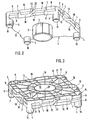
- FIG. 3 The perspective view in FIG. 3 of the rear of the end wall 1, which faces away from the winding roll and points outwards, shows radial ribs 5 and ring ribs 14 which stiffen the rear side and avoid large wall thicknesses, so that the unit weight of the end wall 1 can be kept low .
- the radial and ring ribs result in a high load capacity of the end wall 1 with a low weight.
- the stacking cams 9 and 19 limit stacking pockets 8, 18, which are complementary to the stacking cams.
- the stacking cams 9 are shorter than the stacking cams 19.
- the base body of the two groups of stacking cams 9, 19 is in each case cuboid, one side surface 20 or 21 of the stacking cam 9 or 19 being chamfered and inclined towards the side wall 13.
- Each stacking cam 9 is arranged near one of the two corner surfaces 15 of a side wall 13, the one stacking cam 9 being formed rotated by 180 ° with respect to the other stacking cam 9.
- the two other stacking cams 19 of a side wall 13 are also rotated through 180 ° to one another and offset diagonally to one another, as will be described in more detail below.
- One stack cam 9 and 19 is aligned, for example, with the lower edge of the side wall 13, while the stack cams 19 and 9 rotated by 180 ° are aligned with the upper edge of the side wall 13.
- the group of longer stacking cams 19 also has an incline in addition to the beveled side surface 21 surfaces 22, 23.
- the stack cams 19, 19 rotated relative to one another by 180 ° are arranged such that the diagonally opposite inclined surfaces 22, 23 overlap.
- One end face of the stacking cams 19 is tapered in a wedge shape by the inclined surfaces 22, 23, while the end face 25 of the respective stacking cam 19 opposite these inclined surfaces 22, 23 extends perpendicular to the side wall 13.
- the rest of the group of shorter stacking cams 9 has two end faces 24 perpendicular to the side wall 13 per stacking cam.
- the opposite end faces 24, 25 of the stacking cams 9 and 19 each form the boundary walls for a guide groove 7, which has a strapping band 26 (see FIG 1) takes up the winding roll 27.
- the two end walls of a winding roll are firmly connected to the winding roll by strapping with two strapping bands 26 made of plastic or metal.
- the exact distance of the guide grooves 7 from one another is chosen so that the strapping can be attached by a tandem strapping system. If necessary, the end wall edges can be reinforced at the strapping points and the guide grooves can be given the appropriate strength by an opposite end wall rib.
- the radial ribs 5 and the annular ribs 14 on the back of the plate 11 are at the same height as the outer edge or the edge of the side walls 13 of the plate 11.
- two stacking cams 9 and two stacking cams 19 are provided for each side wall 13. This number of stacking cams is sufficient, for example, with dimensions of 425 x 425 mm of the end wall 1, but it is obvious that with larger dimensions of the end wall, such as 580 x 580 mm or even larger, there are correspondingly more stacking cams 9 and 19 per side wall have to be.
- the number of guide grooves 7 will then also be greater than two.
- the plate 11 has a central cylindrical through opening 12.
- the hollow cylindrical insertion pin 2 is connected to this central through opening 12 via a shoulder 29.
- the diameter of the through opening 12 is larger than the outer diameter of the insertion pin 2.
- On the back of the plate 11 there are recesses 6 which are surrounded by the rounded corner surfaces 15 and rounded webs 17.
- the cutouts 6 connect to the rear of the hollow cylindrical locking cams 4.
- the cam lugs 16 of the locking cams 4 of one end wall engage in the cutouts 6 on the rear side of the plate 11 or the ones lying above them Front wall.
- the insertion pin 2 engages in the through opening 12, which results in the possibility of stacking and palletizing the end walls in a space-saving manner.
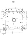
- end walls 1 stacked side by side and one above the other are shown schematically.
- the four side walls of a central end wall 1 are each in engagement with the corresponding side walls of four further end walls. Since the stacking pockets 8, 18, as mentioned above, are designed to be complementary to the stacking cams 9, 19, the stacking cams 9, 19 and the stacking pockets 8, 18 can be stacked or stacked side by side and / or stacked vertically one above the other on the vertically aligned end walls 1 a side wall 13 of an end wall can be joined seamlessly with the complementary stacking pockets 8, 18 and the complementary stacking cams 9, 19 of each of the four side walls 13 of the further end walls 1.
- the stacking cams or stacking pockets engage in one another in such a way that displacement along or across the side wall 13 is not possible.
- the beveled side surfaces 10 of the stacking cams and the stacking pockets allow problem-free stacking and unstacking of the winding rolls packed with these end walls. Mutual locking of the complete winding rolls stacked on one another or next to one another and packed by the end walls 1 is achieved.
- the end walls 1 are produced, for example, from thermoplastic materials by injection molding. Regenerates and recycling materials can be used.
- the stacking cams as well as the webs and ribs are molded in the same injection molding process.
- the individual, vertically aligned end wall can be easily transported on roller conveyors with a roller spacing of 60 to 80 mm, since the stacking cams 9 and 19 of the individual side wall 13 lie with their cover surfaces in the same plane and, moreover, maximally Are 20 mm apart.
Landscapes
- Engineering & Computer Science (AREA)
- Mechanical Engineering (AREA)
- Storage Of Web-Like Or Filamentary Materials (AREA)
- Packaging Of Machine Parts And Wound Products (AREA)
- Stackable Containers (AREA)
- Buffer Packaging (AREA)
- Reinforcement Elements For Buildings (AREA)
- Paper (AREA)
- Rod-Shaped Construction Members (AREA)
- Packaging Of Annular Or Rod-Shaped Articles, Wearing Apparel, Cassettes, Or The Like (AREA)
- Separation, Sorting, Adjustment, Or Bending Of Sheets To Be Conveyed (AREA)
- Laminated Bodies (AREA)
Abstract
Description
- Die Erfindung betrifft eine Stirnwand aus formbarem Material für eine Wickelrolle, mit einer rechteckigen, insbesondere quadratischen, abgerundete Eckflächen aufweisenden Platte, deren der Wickelrolle zugewandte Vorderseite eine glatte, ebene Fläche bildet und deren nach außen von der Wickelrolle wegweisende Rückseite durch Radial- und Ringrippen versteift ist, mit einem zentralen Einsteckzapfen und Arretiernocken auf der Vorderseite der Platte.
- Eine derartige einteilige Stirnwand aus Kunststoff oder einem sonstigen formbaren Werkstoff zur Verpackung von auf Aufwickelhülsen gewickeltem Wickelgut, beispielsweise Kunststoffolien, bildet zusammen mit der zweiten entsprechenden Stirnwand eine formsteife Gesamtverpackung einer Wickelrolle.
- Die übrigen Verpackungen sind im allgemeinen so aufgebaut, daß in eine Kiste aus Holz oder Wellpappe zusätzliche Teile zum zentralen Fixieren der Wickelrolle eingelegt werden. Diese Zusatzteile sind u.a. Holzbretter mit aufgesetzten Naben, gelochte Scheiben aus Sperrholz, Hartfaser, Graupappe mit eingesetzten Zentrierbüchsen aus Blech oder Kunststoff oder teilweise verrippte Formteile aus Kunststoff mit angeformten Aufnahmezapfen aus einem Stück.
- Bei diesen bekannten Verpackungen ist nachteilig, daß sie aus mehreren Einzelteilen bestehen, die zudem nicht kraftschlüssig miteinander verbunden sind, wodurch bei schweren Wickelrollen die Gesamtverpackung nur geringe Stabilität besitzt.
- Bei der eingangs beschriebenen, bekannten Stirnwand ist von Nachteil, daß sie zwar mit weiteren, horizontal ausgerichteten Stirnwänden übereinandergestapelt werden kann, wodurch eine platzsparende Lagerung der Stirnwände möglich ist, jedoch die vertikal ausgerichteten Stirnwände mit ihren Seitenwänden nicht beliebig nebeneinander bzw. übereinander gestapelt und miteinander in Eingriff bzw. gegenseitig arretiert werden können. Dies bedeutet, daß mittels der Stirnwände fertig verpackte Wickelrollen nicht ohne weiteres übereinander gestapelt werden können, da die Stabilität einer derartigen Stapelung nicht gewährleistet ist.
- Aus dem deutschen Gebrauchsmuster 19 91 976 ist eine einteilige Stirnwand aus Kunststoff bekannt, die aus einer viereckigen, vorzugsweise quadratischen, mit Radialstegen versteiften ebenen Platte besteht. In der Mitte befindet sich ein Einsteckzapfen für die Wickelgutrolle, der beispielsweise mit Halteprismen ausgestattet ist. Die Platte wird von einem Gurt umhüllt, auf dessen Außenseite kleine prismenförmige Leisten angeordnet sind. Der Gurt schließt an den Ecken der Platte vier in den freien Hohlraum zwischen Wickelgut und Verpackungsmantel hineinragende, nahe der äußeren Stirnseite hin offene becherförmige Vertiefungen ein und besitzt eine umlaufende Anschlagleiste, die mit Zähnen versehen ist.
- Aufgabe der Erfindung ist es, Stirnwände der eingangs beschriebenen Art so zu verbessern, daß eine gegenseitige Arretierung der Stirnwände mehrerer aufeinander und/oder nebeneinander gestapelter kompletter Rollen, die von den Stirnwänden abgeschlossen sind, gewährleistet ist, wobei die Stirnwände mit jeder ihrer Seitenwände ineinandergreifen können, ohne daß eine bestimmte Vorauswahl der Ausrichtung der Seitenwände zueinander getroffen werden muß.
- Diese Aufgabe wird erfindungsgemäß dadurch gelöst, daß auf jeder der vier Seitenwände der Platte Stapelnocken vorhanden sind, die Stapeltaschen begrenzen und daß die Stapeltaschen komplementär zu den Stapelnocken ausgebildet sind, so daß beim seitlichen Zusammenstapeln und/oder vertikalen Übereinanderstapeln senkrecht ausgerichteter Stirnwände die Stapelnocken und -taschen einer Seitenwand einer Stirnwand fugenlos mit den Stapeltaschen und -nocken jeder der vier Seitenwände einer weiteren Stirnwand zusammfügbar sind.
- In Weiterbildung der Erfindung haben die mit den abgerundeten Eckflächen der Stirnwand integrierten zylindrischen Arretiernocken den gleichen Radius wie die abgerundeten Eckflächen, ist jeder Arretiernocken mit einem durch eine Schulter abgesetzten zylindrischen Nockenansatz ausgestattet, greifen die Nockenansätze der Arretiernocken einer Stirnwand beim Übereinanderstapeln horizontal ausgerichteter Stirnwände in Aussparungen auf der Rückseite der darüber liegenden Stirnwand ein und schließen die Aussparungen an die hohlzylindrischen Arretiernocken an und sind von den abgerundeten Eckflächen und abgerundeten Stegen umschlossen.
- In Ausgestaltung der Erfindung weisen die Stapelnocken angeschrägte Seitenflächen auf, die zur Mittellinie der Seitenwand hin geneigt sind und fluchten paarweise Stapelnocken mit der Oberkante und mit der Unterkante einer Seitenwand.
- Die weitere Ausgestaltung der Erfindung ergibt sich aus den Patentansprüchen 4 bis 7.
- Mit der Erfindung wird der Vorteil erzielt, daß die Stapelnocken und Stapeltaschen der Stirnwände so ineinandergreifen, daß ein Verschieben der aufeinander und/oder nebeneinander gestapelten kompletten Rollen mit den begrenzenden Stirnwänden längs oder quer nicht möglich ist. Die angeschrägten Seitenflächen der Stapelnocken und Stapeltaschen erlauben ein problemloses Stapeln und Entstapeln der mit diesen Stirnwänden verpackten Rollen.
- Die Erfindung wird im folgenden anhand eines zeichnerisch dargestellten Ausführungsbeispiels näher er läutert. Es zeigen:
- Fig. 1 schematisch eine auf eine Aufwickelhülse aufgewickelte Wickelrolle, die von Stirnwänden nach der Erfindung begrenzt ist,
- Fig. 2 eine perspektivische Ansicht der Vorderseite der Stirnwand nach der Erfindung,
- Fig. 3 eine perspektivische Ansicht der Rückseite der Stirnwand,
und - Fig. 4 schematisch eine Ansicht nebeneinander und übereinander gestapelter Stirnwände, mit einer zentralen Stirnwand, deren vier Seitenwände mit jeweils einer Seitenwand von vier weiteren Stirnwänden im Eingriff steht.
- In Figur 1 ist schematisch eine vollständige Wickelrolle 27 dargestellt, die auf eine Aufwickelhülse 28 aufgewickelt ist. Die Stirnflächen der Wickelrolle 27 werden von Stirnwänden 1 begrenzt, von denen jede einen zentralen Einsteckzapfen 2 aufweist, der in die Aufwickelhülse 28 eingeschoben ist. Die Stirnwand 1 besteht aus einer rechteckigen, insbesondere quadratischen Platte 11, an deren vier Ecken Arretiernocken 4 angeordnet sind, die Nockenansätze 16 aufweisen. Auf jeder der vier Seitenwände 13 der Platte 11 einer Stirnwand 1 sind Sta pelnocken 9, 19 vorhanden, die unterschiedliche Länge und unterschiedliche Querschnitte besitzen.
- Wie aus der perspektivischen Ansicht der Vorderseite der Stirnwand 1 in Figur 2 ersichtlich ist, sind Eckflächen 15 der Stirnwand 1 abgerundet, und die zylindrischen Arretiernocken 4 sind mit diesen Eckflächen integriert und haben den gleichen Radius wie die abgerundeten Eckflächen 15. Die zylindrischen Nockenansätze 16 sind durch eine Schulter von den Arretiernocken 4 abgesetzt und weisen einen geringeren Durchmesser als die Arretiernocken auf. Die glatte oder plane Vorderseite, die der Wickelrolle zugewandt ist, schützt die Stirnseite der Wickelrolle, insbesondere beim Transport, vor Beschädigungen.
- An der Außenfläche des Einsteckzapfens 2 verlaufen parallel zur Längsachse des Einsteckzapfens V-förmige Stege 3, die zur Vorderseite der Platte 11 hin kleiner werdenden Querschnitt besitzen. Der Einsteckzapfen 2 wird in die Bohrung der Aufwickelhülse 28 (vgl. Figur 1) eingedrückt. Die V-förmigen Stege 3 auf dem Einsteckzapfen 2 gewährleisten einen besseren Halt des Einsteckzapfens in der Aufwickelhülse 28 und gleichen Dimensionstoleranzen der Aufwickelhülse einerseits und des Einsteckzapfens andererseits aus. Die Durchmesser der hohlzylindrischen Einsteckzapfen 2 werden den Durchmessern der jeweiligen Bohrung der Aufwickelhülse 28 angepaßt.
- Die perspektivische Ansicht in Figur 3 der Rückseite der Stirnwand 1, die von der Wickelrolle abgewandt ist und nach außen weist, zeigt Radialrippen 5 und Ringrippen 14, welche die Rückseite versteifen und große Wandstärken vermeiden, so daß das Stückgewicht der Stirnwand 1 gering gehalten werden kann. Die Radial- und Ringrippen ergeben eine hohe Belastbarkeit der Stirnwand 1 bei geringem Eigengewicht. Wie aus den Figuren 1 und 2 ersichtlich ist, begrenzen die Stapelnocken 9 und 19 Stapeltaschen 8, 18, die komplementär zu den Stapelnocken ausgebildet sind. Die Stapelnocken 9 sind kürzer als die Stapelnocken 19. Der Grundkörper der beiden Gruppen von Stapelnocken 9, 19 ist jeweils quaderförmig, wobei die eine Seitenfläche 20 bzw. 21 des Stapelnockens 9 bzw. 19 angeschrägt ist und zur Seitenwand 13 hin geneigt ist. Je ein Stapelnocken 9 ist nahe einer der beiden Eckflächen 15 einer Seitenwand 13 angeordnet, wobei der eine Stapelnocken 9 um 180° gedreht gegenüber dem anderen Stapelnocken 9 ausgebildet ist. Die beiden anderen Stapelnocken 19 einer Seitenwand 13 sind gleichfalls um 180° zueinander gedreht und zueinander diagonal versetzt, wie noch näher beschrieben werden wird. Je ein Stapelnocken 9 und 19 fluchtet beispielsweise mit der Unterkante der Seitenwand 13, während die dazu um 180° gedrehten Stapelnocken 19 und 9 mit der Oberkante der Seitenwand 13 fluchten.
- Die Gruppe der längeren Stapelnocken 19 weist zusätzlich zu der angeschrägten Seitenfläche 21 noch Schräg flächen 22, 23 auf. Die zueinander um 180° gedrehten, einander gegenüberliegenden Stapelnocken 19, 19 sind so angeordnet, daß sich die einander diagonal gegenüberliegenden Schrägflächen 22, 23 überlappen. Durch die Schrägflächen 22, 23 ist die eine Stirnseite der Stapelnocken 19 keilförmig zugespitzt, während die diesen Schrägflächen 22, 23 gegenüberliegende Stirnfläche 25 des jeweiligen Stapelnockens 19 senkrecht zur Seitenwand 13 verläuft. Die übrige Gruppe der kürzeren Stapelnocken 9 besitzt pro Stapelnocken zwei senkrecht zur Seitenwand 13 verlaufende Stirnflächen 24. Die einander im Abstand gegenüberliegenden Stirnflächen 24, 25 der Stapelnocken 9 und 19 bilden jeweils die Begrenzungswände für eine Führungsnut 7, die ein Umreifungsband 26 (vgl. Fig. 1) der Wickelrolle 27 aufnimmt.
- An allen vier Seitenwänden 13 befinden sich jeweils mindestens zwei Führungsnuten 7, die beispielsweise 20 mm breit und etwa 10 mm tief sind.
- Die beiden Stirnwände einer Wickelrolle werden durch Umreifen mit zwei Umreifungsbändern 26 aus Kunststoff oder Metall fest mit der Aufwickelrolle verbunden. Der genaue Abstand der Führungsnuten 7 voneinander wird so gewählt, daß die Umreifungsbänder durch eine Tandem-Umreifungsanlage angebracht werden können. Falls es erforderlich ist, können die Stirnwandränder an den Umreifungsstellen verstärkt sein und die Führungsnuten durch eine gegenüberliegende Stirnwandrippe die entsprechende Festigkeit erhalten.
- Die Radialrippen 5 sowie die Ringrippen 14 der Rückseite der Platte 11 befinden sich auf gleicher Höhe wie der Außenrand bzw. die Kante der Seitenwände 13 der Platte 11. Bei dem beschriebenen Ausführungsbeispiel sind pro Seitenwand 13 jeweils zwei Stapelnocken 9 und zwei Stapelnocken 19 vorgesehen. Diese Anzahl der Stapelnocken reicht beispielsweise bei Abmessungen von 425 x 425 mm der Stirnwand 1 aus, jedoch liegt es auf der Hand, daß bei größeren Abmessungen der Stirnwand, wie beispielsweise 580 x 580 mm oder noch größer entsprechend mehr Stapelnocken 9 und 19 pro Seitenwand vorhanden sein müssen. Es wird dann auch die Anzahl der Führungsnuten 7 größer als zwei sein.
- Wie aus Figur 3 ersichtlich ist, weist die Platte 11 eine zentrale zylindrische Durchgangsöffnung 12 auf. Der hohlzylindrische Einsteckzapfen 2 ist über eine Schulter 29 mit dieser zentralen Durchgangsöffnung 12 verbunden. Der Durchmesser der Durchgangsöffnung 12 ist größer als der Außendurchmesser des Einsteckzapfens 2. Auf der Rückseite der Platte 11 befinden sich Aussparungen 6, die von den abgerundeten Eckflächen 15 und abgerundeten Stegen 17 umschlossen sind. Die Aussparungen 6 schließen an die Rückseite der hohlzylindrischen Arretiernocken 4 an.
- Werden zwei horizontal ausgerichtete Stirnwände 1 übereinandergestapelt, so greifen die Nockenansätze 16 der Arretiernocken 4 einer Stirnwand in die Aussparungen 6 auf der Rückseite der Platte 11 der darüber liegenden Stirnwand ein. Ebenso greift der Einsteckzapfen 2 in die Durchgangsöffnung 12 ein, wodurch sich die Möglichkeit ergibt, die Stirnwände platzsparend zu stapeln und zu palettieren.
- In Figur 4 sind schematisch seitlich nebeneinander und übereinander gestapelte Stirnwände 1 dargestellt. Dabei stehen die vier Seitenwände einer zentralen Stirnwand 1 jeweils mit den entsprechenden Seitenwänden von vier weiteren Stirnwänden im Eingriff. Da die Stapeltaschen 8, 18, wie voranstehend erwähnt ist, komplementär zu den Stapelnocken 9, 19 ausgebildet sind, können beim seitlichen Zusammenstapeln bzw. Nebeneinanderstapeln und/oder vertikalen Übereinanderstapeln der senkrecht ausgerichteten Stirnwände 1 die Stapelnocken 9, 19 und die Stapeltaschen 8, 18 einer Seitenwand 13 einer Stirnwand fugenlos mit den komplementären Stapeltaschen 8, 18 und den komplementären Stapelnocken 9, 19 jeder der vier Seitenwände 13 der weiteren Stirnwände 1 zusammengefügt werden.
- Die Stapelnocken oder Stapeltaschen greifen so ineinander, daß ein Verschieben längs oder quer zu der Seitenwand 13 nicht möglich ist. Die angeschrägten Seitenflächen 10 der Stapelnocken und der Stapeltaschen erlauben ein problemloses Stapeln und Entstapeln der mit diesen Stirnwänden verpackten Wickelrollen. Es wird eine gegenseitige Arretierung der aufeinander oder nebeneinander gestapelten, durch die Stirnwände 1 abgepackten kompletten Wickelrollen erreicht.
- Die Stirnwände 1 werden beispielsweise aus thermoplastischen Kunststoffen im Spritzgießverfahren hergestellt. Dabei können Regenerate und Recycling-Materialien eingesetzt werden. Dabei werden die Stapelnocken, ebenso wie die Stege und Rippen, im gleichen Spritzgießvorgang ausgeformt.
- Da alle vier Seitenwände 13 der Stirnwand bezüglich der Stapelnocken oder Stapeltaschen gleich ausgebildet sind, ist ein seitliches Nebeneinanderstapeln und/oder Übereinanderstapeln der mit den Stirnwänden abgeschlossenen Wickelrollen jederzeit möglich, da jede Seitenwand der einen Stirnwand mit jeder Seitenwand einer weiteren Stirnwand in Eingriff gebracht werden kann, ohne daß eine bevorzugte Ausrichtung der Stirnwände zueinander notwendig ist. Mit anderen Worten bedeutet dies, daß die Stapelnocken und Stapeltaschen in jeder Lage der Stirnwände, ob vertikal oder horizontal ausgerichtet, ineinander eingreifen bzw. einrasten. Von Vorteil ist auch, daß die einzelne, vertikal ausgerichtete Stirnwand problemlos auf Rollenbahnen mit einem Rollenabstand von 60 bis 80 mm transportiert werden kann, da die Stapelnocken 9 bzw. 19 der einzelnen Seitenwand 13 mit ihren Deckflächen in der gleichen Ebene liegen und darüber hinaus maximal 20 mm voneinander beabstandet sind.
Claims (7)
Priority Applications (1)
| Application Number | Priority Date | Filing Date | Title |
|---|---|---|---|
| AT89104178T ATE91476T1 (de) | 1988-03-11 | 1989-03-09 | Stirnwand aus formbarem material fuer eine wickelrolle. |
Applications Claiming Priority (2)
| Application Number | Priority Date | Filing Date | Title |
|---|---|---|---|
| DE3808064 | 1988-03-11 | ||
| DE3808064A DE3808064C1 (de) | 1988-03-11 | 1988-03-11 |
Publications (4)
| Publication Number | Publication Date |
|---|---|
| EP0332186A2 true EP0332186A2 (de) | 1989-09-13 |
| EP0332186A3 EP0332186A3 (en) | 1990-03-21 |
| EP0332186B1 EP0332186B1 (de) | 1993-07-14 |
| EP0332186B2 EP0332186B2 (de) | 1995-12-27 |
Family
ID=6349436
Family Applications (1)
| Application Number | Title | Priority Date | Filing Date |
|---|---|---|---|
| EP89104178A Expired - Lifetime EP0332186B2 (de) | 1988-03-11 | 1989-03-09 | Stirnwand aus formbarem Material für eine Wickelrolle |
Country Status (8)
| Country | Link |
|---|---|
| US (1) | US4884690A (de) |
| EP (1) | EP0332186B2 (de) |
| JP (1) | JP2639512B2 (de) |
| KR (1) | KR0139921B1 (de) |
| AT (1) | ATE91476T1 (de) |
| DE (2) | DE3808064C1 (de) |
| HK (1) | HK80896A (de) |
| ZA (1) | ZA891804B (de) |
Cited By (6)
| Publication number | Priority date | Publication date | Assignee | Title |
|---|---|---|---|---|
| EP0447737A1 (de) * | 1990-03-19 | 1991-09-25 | Eso-Plast - S.R.L. | Plastisch geformte Trägerplatte zum Herstellen von Rollstützen, die mit anderen Platten desselben Types nebeneinander angeordnet, aufeinandergelegt und festgesetzt werden |
| EP0522450A1 (de) * | 1991-07-08 | 1993-01-13 | Hoechst Aktiengesellschaft | Wickelrollenstirnwand mit verbesserter Seitenbruchsicherheit |
| EP0535481A3 (en) * | 1991-09-28 | 1993-12-15 | Hoechst Ag | End wall made from deformable material without sharings for use with a core of rolled material |
| EP0504394A4 (en) * | 1990-10-04 | 1994-06-29 | Joseph L Cobane | Fabric roll |
| JP2015183820A (ja) * | 2014-03-26 | 2015-10-22 | 三甲株式会社 | ロール保持盤 |
| CN107150886A (zh) * | 2016-03-04 | 2017-09-12 | 菲涅尔有限公司 | 用于安装在太阳能发电场中的镜单元的运输装置和运输方法 |
Families Citing this family (41)
| Publication number | Priority date | Publication date | Assignee | Title |
|---|---|---|---|---|
| USD333093S (en) | 1989-09-19 | 1993-02-09 | Rehrig-Pacific Company, Inc. | Divider for bottles or the like |
| DE9006966U1 (de) * | 1990-06-22 | 1991-10-17 | Hoechst Ag, 6230 Frankfurt | Transport- und Verpackungssystem für mechanisch empfindliche Güter in Großrollenformat |
| DE9006964U1 (de) * | 1990-06-22 | 1991-10-17 | Hoechst Ag, 6230 Frankfurt | Transport- und Verpackungseinheit für Güter in Großrollenformat mit reduziertem Eigenvolumen |
| JP2507188Y2 (ja) * | 1991-04-18 | 1996-08-14 | 株式会社シンワコーポレーション | 鋼板コイルの包装構造 |
| DE4241115A1 (de) * | 1992-12-07 | 1994-06-09 | Hoechst Ag | Stirnwand aus Spritzgußmaterial für eine Wickelfolie |
| US5529186A (en) * | 1994-12-09 | 1996-06-25 | At&T Corp. | Boxed pay-out reel for optic fiber cable or wire or the like, with smooth pay-out, high-impact and cable end holding features |
| US5542534A (en) * | 1994-12-15 | 1996-08-06 | Hoechst Aktiengesellschaft | Packaging system for receiving a film web wound up in roll form onto a winding sleeve |
| DE19524954A1 (de) * | 1995-07-08 | 1997-01-09 | Hoechst Ag | Stirnwand aus formbarem Material |
| USD390316S (en) | 1996-06-13 | 1998-02-03 | Smith Stacey D | End board pad |
| US6234421B1 (en) | 1996-10-24 | 2001-05-22 | Vandor Corporation | Reel having secured flanges |
| US6785946B2 (en) | 1999-04-30 | 2004-09-07 | Kimberly-Clark Worldwide, Inc. | System and method for refilling a dispenser |
| US6705565B1 (en) | 1999-04-30 | 2004-03-16 | Kimberly-Clark Worldwide, Inc. | System and dispenser for dispensing wet wipes |
| US6537631B1 (en) | 1999-04-30 | 2003-03-25 | Kimberly-Clark Worldwide, Inc. | Roll of wet wipes |
| US7188799B1 (en) | 1999-04-30 | 2007-03-13 | Kimberly-Clark Worldwide, Inc. | Dispensing system for wipes |
| US6279865B1 (en) | 1999-04-30 | 2001-08-28 | Kimberly-Clark Worldwide, Inc. | Mounting device |
| US6626395B1 (en) | 1999-04-30 | 2003-09-30 | Kimberly-Clark Worldwide, Inc. | Dispenser for premoistened wipes |
| US6682013B1 (en) | 1999-04-30 | 2004-01-27 | Kimberly Clark Worldwide, Inc. | Container for wet wipes |
| US6273359B1 (en) | 1999-04-30 | 2001-08-14 | Kimberly-Clark Worldwide, Inc. | Dispensing system and method for premoistened wipes |
| US6702225B2 (en) | 1999-04-30 | 2004-03-09 | Kimberly-Clark Worldwide, Inc. | Dispenser and tray for premoistened wipes |
| US6702227B1 (en) | 1999-04-30 | 2004-03-09 | Kimberly-Clark Worldwide, Inc. | Wipes dispensing system |
| US6745975B2 (en) | 1999-04-30 | 2004-06-08 | Kimberly-Clark Worldwide, Inc. | System for dispensing plurality of wet wipes |
| CA2400832A1 (en) | 2000-04-10 | 2001-10-18 | Kimberly-Clark Worldwide, Inc. | Wipes dispensing system |
| US7063245B2 (en) | 2000-05-04 | 2006-06-20 | Kimberly-Clark Worldwide, Inc. | System for dispensing plurality of wet wipes |
| USD462215S1 (en) | 2000-09-12 | 2002-09-03 | Kimberly-Clark Worldwide, Inc. | Dispenser |
| USD457765S1 (en) | 2000-09-12 | 2002-05-28 | Kimberly Clark Worldwide, Inc. | Surface pattern applied to a dispenser |
| US6827309B1 (en) | 2000-09-12 | 2004-12-07 | Kimberly-Clark Worldwide, Inc. | Mounting system for a wet wipes dispenser |
| US6568625B2 (en) | 2001-07-27 | 2003-05-27 | Kimberly-Clark Worldwide, Inc. | Wet wipes dispenser and mounting system |
| US7354598B2 (en) | 2002-12-20 | 2008-04-08 | Kimberly-Clark Worldwide, Inc. | Packaging two different substrates |
| US20040251292A1 (en) * | 2003-06-13 | 2004-12-16 | Grebonval Loic Henri Raymond | Package containing two different substrates |
| US7293738B2 (en) | 2003-11-26 | 2007-11-13 | Kimberly-Clark Worldwide, Inc. | Freestanding dispenser for dispensing two different substrates |
| US6994291B2 (en) * | 2003-12-22 | 2006-02-07 | Exxonmobil Oil Corporation | End-board for a core-wound roll product packaging system |
| DE102006007332A1 (de) * | 2006-02-16 | 2007-08-30 | Schoeller Arca Systems Services Gmbh | Mehrfach verwendbare Transporteinheit für Folienrollen und dergleichen |
| DE102006017363B4 (de) * | 2006-04-11 | 2008-05-29 | Lkh-Kunststoffwerk Gmbh & Co. Kg | Stirnwand für eine Wickelgutrolle und Anordnung von Stirnwänden |
| JP2008037558A (ja) * | 2006-08-04 | 2008-02-21 | Kaneka Corp | 巻物受け具 |
| US20100261592A1 (en) * | 2008-07-24 | 2010-10-14 | Kuo-Chang Wu | Tube Plug |
| JP5806896B2 (ja) * | 2011-09-21 | 2015-11-10 | 三甲株式会社 | ロール状資材の運搬保管用部材 |
| US9284103B2 (en) | 2013-11-05 | 2016-03-15 | Sonoco Development, Inc. | End support for wound rolls |
| CN104340539A (zh) * | 2014-09-10 | 2015-02-11 | 费志勤 | 封头板安装座 |
| JP6974259B2 (ja) | 2018-06-08 | 2021-12-01 | 旭化成株式会社 | 保持体、保持体ユニット及び保持体ユニットの集合体 |
| WO2022225076A1 (ko) * | 2021-04-21 | 2022-10-27 | 유명일 | 롤필름 홀더 |
| CN118637189A (zh) * | 2024-07-02 | 2024-09-13 | 苏州天裕塑胶有限公司 | 一种卷材运输存储装置及使用方法 |
Family Cites Families (15)
| Publication number | Priority date | Publication date | Assignee | Title |
|---|---|---|---|---|
| DE1991976U (de) * | 1968-08-14 | Kalk Aktiengesellschaft, 6202 Wiesbaden Biebnch | Stirnwand fur Verpackungen | |
| DE1174687B (de) * | 1961-04-20 | 1964-07-23 | Mauser Kg | Behaelter |
| BE646210A (de) * | 1964-04-07 | 1964-07-31 | ||
| US3352410A (en) * | 1966-02-28 | 1967-11-14 | Salladay Mark | Wrapping material roll package and roll support therefor |
| ES149014Y (es) * | 1968-05-30 | 1970-05-16 | Una pared frontal. | |
| DE1954298A1 (de) * | 1969-10-29 | 1971-05-06 | Zagelow Guenther Dipl Ing | Selbsttragende Mehrportionensteige |
| US3606002A (en) * | 1970-02-12 | 1971-09-20 | James A Miller | Stabilizer for a plurality of abutting rectilinear surfaces |
| US3737028A (en) * | 1971-04-08 | 1973-06-05 | Morgan Adhesives Co | Packaged adhesive laminate and method of making the same |
| US3942638A (en) * | 1975-03-14 | 1976-03-09 | Stone Harris E | Cap assemblage for hard surface floor covering roll and method for making same |
| GB1497929A (en) * | 1975-10-31 | 1978-01-12 | Firbank R | Storage and transport of roll-up doors or other cylindrical objects |
| AU548221B2 (en) * | 1981-08-24 | 1985-11-28 | Bigelow-Sanford Inc. | Pallet |
| US4398653A (en) * | 1982-02-25 | 1983-08-16 | Pennsylvania Pacific Corporation | Portable storage and dispenser plastic hopper with plastic base |
| US4491222A (en) * | 1983-07-18 | 1985-01-01 | International Business Machines Corporation | Reel package |
| DE8520270U1 (de) * | 1985-07-13 | 1985-10-03 | Thorwarth & Grebe oHG, 5927 Erndtebrück | Stützwange für auf rohrförmigen Trägerkernen sitzende Folienwickel |
| US4690345A (en) * | 1986-03-31 | 1987-09-01 | John Cotey | Portable dispenser for rolled paper products |
-
1988
- 1988-03-11 DE DE3808064A patent/DE3808064C1/de not_active Expired
-
1989
- 1989-03-08 US US07/320,712 patent/US4884690A/en not_active Expired - Lifetime
- 1989-03-09 EP EP89104178A patent/EP0332186B2/de not_active Expired - Lifetime
- 1989-03-09 ZA ZA891804A patent/ZA891804B/xx unknown
- 1989-03-09 AT AT89104178T patent/ATE91476T1/de not_active IP Right Cessation
- 1989-03-09 DE DE8989104178T patent/DE58904890D1/de not_active Expired - Lifetime
- 1989-03-10 KR KR1019890002937A patent/KR0139921B1/ko not_active Expired - Lifetime
- 1989-03-13 JP JP1058056A patent/JP2639512B2/ja not_active Expired - Lifetime
-
1996
- 1996-05-09 HK HK80896A patent/HK80896A/xx not_active IP Right Cessation
Cited By (7)
| Publication number | Priority date | Publication date | Assignee | Title |
|---|---|---|---|---|
| EP0447737A1 (de) * | 1990-03-19 | 1991-09-25 | Eso-Plast - S.R.L. | Plastisch geformte Trägerplatte zum Herstellen von Rollstützen, die mit anderen Platten desselben Types nebeneinander angeordnet, aufeinandergelegt und festgesetzt werden |
| EP0504394A4 (en) * | 1990-10-04 | 1994-06-29 | Joseph L Cobane | Fabric roll |
| EP0522450A1 (de) * | 1991-07-08 | 1993-01-13 | Hoechst Aktiengesellschaft | Wickelrollenstirnwand mit verbesserter Seitenbruchsicherheit |
| US5205411A (en) * | 1991-07-08 | 1993-04-27 | Hoechst Aktiengesellschaft | End wall for a wound roll, exhibiting improved resistance to lateral breaking |
| EP0535481A3 (en) * | 1991-09-28 | 1993-12-15 | Hoechst Ag | End wall made from deformable material without sharings for use with a core of rolled material |
| JP2015183820A (ja) * | 2014-03-26 | 2015-10-22 | 三甲株式会社 | ロール保持盤 |
| CN107150886A (zh) * | 2016-03-04 | 2017-09-12 | 菲涅尔有限公司 | 用于安装在太阳能发电场中的镜单元的运输装置和运输方法 |
Also Published As
| Publication number | Publication date |
|---|---|
| EP0332186A3 (en) | 1990-03-21 |
| JP2639512B2 (ja) | 1997-08-13 |
| JPH01294456A (ja) | 1989-11-28 |
| KR890014953A (ko) | 1989-10-25 |
| HK80896A (en) | 1996-05-17 |
| ATE91476T1 (de) | 1993-07-15 |
| DE3808064C1 (de) | 1989-03-30 |
| DE58904890D1 (de) | 1993-08-19 |
| US4884690A (en) | 1989-12-05 |
| KR0139921B1 (ko) | 1998-07-01 |
| EP0332186B1 (de) | 1993-07-14 |
| ZA891804B (en) | 1989-10-25 |
| EP0332186B2 (de) | 1995-12-27 |
Similar Documents
| Publication | Publication Date | Title |
|---|---|---|
| EP0332186B1 (de) | Stirnwand aus formbarem Material für eine Wickelrolle | |
| EP0332185B1 (de) | Stirnwand aus formbarem Material für eine Wickelrolle | |
| EP0535481B1 (de) | Stirnwand aus spanlos verformbarem Material für eine Wickelfolie | |
| EP3636559A1 (de) | Stapelbare kiste | |
| DE69112794T2 (de) | Palette zum Transportieren von zylindrischen Gegenständen und Halterungsteil zum Stützen ihres Zentralrohres. | |
| EP0522450B1 (de) | Wickelrollenstirnwand mit verbesserter Seitenbruchsicherheit | |
| EP0601494B1 (de) | Stirnwand aus Spritzgussmaterial für eine Wickelfolie | |
| DE2255316B2 (de) | Flaschenkasten | |
| EP0753469B1 (de) | Stirnwand aus formbarem Material | |
| EP0357906B1 (de) | Einrichtung zum Zuführen von Zuschnitten zu einer Verpackungsmaschine | |
| EP0265581A1 (de) | Konischer Stapelkasten | |
| DE4128770C2 (de) | Behältersystem mit profilierten Platten sowie Vorrichtung zum Befüllen und Entladen hierfür | |
| DE3404453C2 (de) | Kasten aus formstabilem Kunststoff, insbesondere Flaschenkasten | |
| EP1634815A1 (de) | Drehstapelbehälter | |
| DE3004673C2 (de) | ||
| EP0367168A1 (de) | Flaschenkasten | |
| AT401038B (de) | Rechteckige transporttasse | |
| EP0236514A1 (de) | Transport- und Lagerkasten aus Kunststoff | |
| DE9210943U1 (de) | Kastenartiges Behältnis | |
| DE2400049A1 (de) | Transportkasten aus kunststoff, insbesondere fuer flaschen | |
| EP1110875A2 (de) | Transportsystem mit Flaschenträger | |
| DE29614562U1 (de) | Ständer zum Lagern und Stapeln von Behältern | |
| DE102006017363B4 (de) | Stirnwand für eine Wickelgutrolle und Anordnung von Stirnwänden | |
| DE2428316C3 (de) | Stapelbare Steige aus Kunststoff | |
| DE7400009U (de) | Transportkasten aus Kunststoff, insbesondere für Flaschen |
Legal Events
| Date | Code | Title | Description |
|---|---|---|---|
| PUAI | Public reference made under article 153(3) epc to a published international application that has entered the european phase |
Free format text: ORIGINAL CODE: 0009012 |
|
| AK | Designated contracting states |
Kind code of ref document: A2 Designated state(s): AT BE CH DE FR GB IT LI LU |
|
| PUAL | Search report despatched |
Free format text: ORIGINAL CODE: 0009013 |
|
| AK | Designated contracting states |
Kind code of ref document: A3 Designated state(s): AT BE CH DE FR GB IT LI LU |
|
| 17P | Request for examination filed |
Effective date: 19900627 |
|
| 17Q | First examination report despatched |
Effective date: 19920602 |
|
| GRAA | (expected) grant |
Free format text: ORIGINAL CODE: 0009210 |
|
| AK | Designated contracting states |
Kind code of ref document: B1 Designated state(s): AT BE CH DE FR GB IT LI LU |
|
| REF | Corresponds to: |
Ref document number: 91476 Country of ref document: AT Date of ref document: 19930715 Kind code of ref document: T |
|
| REF | Corresponds to: |
Ref document number: 58904890 Country of ref document: DE Date of ref document: 19930819 |
|
| ET | Fr: translation filed | ||
| ITF | It: translation for a ep patent filed | ||
| GBT | Gb: translation of ep patent filed (gb section 77(6)(a)/1977) |
Effective date: 19931015 |
|
| ITTA | It: last paid annual fee | ||
| PLBI | Opposition filed |
Free format text: ORIGINAL CODE: 0009260 |
|
| EPTA | Lu: last paid annual fee | ||
| 26 | Opposition filed |
Opponent name: IMPERIAL CHEMICAL INDUSTRIES PLC, GROUP PATENTS SE Effective date: 19940413 |
|
| PLAB | Opposition data, opponent's data or that of the opponent's representative modified |
Free format text: ORIGINAL CODE: 0009299OPPO |
|
| R26 | Opposition filed (corrected) |
Opponent name: IMPERIAL CHEMICAL INDUSTRIES PLC, THE MANAGER, INT Effective date: 19940413 |
|
| PUAH | Patent maintained in amended form |
Free format text: ORIGINAL CODE: 0009272 |
|
| STAA | Information on the status of an ep patent application or granted ep patent |
Free format text: STATUS: PATENT MAINTAINED AS AMENDED |
|
| 27A | Patent maintained in amended form |
Effective date: 19951227 |
|
| AK | Designated contracting states |
Kind code of ref document: B2 Designated state(s): AT BE CH DE FR GB IT LI LU |
|
| REG | Reference to a national code |
Ref country code: CH Ref legal event code: AEN Free format text: AUFRECHTERHALTUNG DES PATENTES IN GEAENDERTER FORM |
|
| GBTA | Gb: translation of amended ep patent filed (gb section 77(6)(b)/1977) |
Effective date: 19960124 |
|
| ITF | It: translation for a ep patent filed | ||
| ET3 | Fr: translation filed ** decision concerning opposition | ||
| REG | Reference to a national code |
Ref country code: GB Ref legal event code: IF02 |
|
| REG | Reference to a national code |
Ref country code: CH Ref legal event code: PUE Owner name: SONOCO PLASTICS GERMANY GMBH Free format text: HOECHST AKTIENGESELLSCHAFT#POSTFACH 80 03 20#D-65926 FRANKFURT (DE) -TRANSFER TO- SONOCO PLASTICS GERMANY GMBH#AM AGGERBERG 17#51491 OVERATH-VILKERATH (DE) |
|
| BECA | Be: change of holder's address |
Owner name: *SONOCO PLASTICS GERMANY G.M.B.H.AM AGGERBERG 17, Effective date: 20050217 |
|
| REG | Reference to a national code |
Ref country code: GB Ref legal event code: 732E |
|
| REG | Reference to a national code |
Ref country code: FR Ref legal event code: TP |
|
| BECA | Be: change of holder's address |
Owner name: *SONOCO PLASTICS GERMANY G.M.B.H.AM AGGERBERG 17, Effective date: 20050217 |
|
| PGFP | Annual fee paid to national office [announced via postgrant information from national office to epo] |
Ref country code: CH Payment date: 20080228 Year of fee payment: 20 |
|
| PGFP | Annual fee paid to national office [announced via postgrant information from national office to epo] |
Ref country code: GB Payment date: 20080305 Year of fee payment: 20 Ref country code: IT Payment date: 20080327 Year of fee payment: 20 Ref country code: LU Payment date: 20080313 Year of fee payment: 20 |
|
| PGFP | Annual fee paid to national office [announced via postgrant information from national office to epo] |
Ref country code: AT Payment date: 20080313 Year of fee payment: 20 |
|
| PGFP | Annual fee paid to national office [announced via postgrant information from national office to epo] |
Ref country code: DE Payment date: 20080331 Year of fee payment: 20 Ref country code: FR Payment date: 20080311 Year of fee payment: 20 |
|
| PGFP | Annual fee paid to national office [announced via postgrant information from national office to epo] |
Ref country code: BE Payment date: 20080916 Year of fee payment: 20 |
|
| BE20 | Be: patent expired |
Owner name: *SONOCO PLASTICS GERMANY G.M.B.H. Effective date: 20090309 |
|
| REG | Reference to a national code |
Ref country code: CH Ref legal event code: PL |
|
| REG | Reference to a national code |
Ref country code: GB Ref legal event code: PE20 Expiry date: 20090308 |
|
| PG25 | Lapsed in a contracting state [announced via postgrant information from national office to epo] |
Ref country code: GB Free format text: LAPSE BECAUSE OF EXPIRATION OF PROTECTION Effective date: 20090308 |