EP0332209B1 - Tube - Google Patents
Tube Download PDFInfo
- Publication number
- EP0332209B1 EP0332209B1 EP89104293A EP89104293A EP0332209B1 EP 0332209 B1 EP0332209 B1 EP 0332209B1 EP 89104293 A EP89104293 A EP 89104293A EP 89104293 A EP89104293 A EP 89104293A EP 0332209 B1 EP0332209 B1 EP 0332209B1
- Authority
- EP
- European Patent Office
- Prior art keywords
- tube
- intermediate sleeve
- pieces
- tube according
- pipe
- Prior art date
- Legal status (The legal status is an assumption and is not a legal conclusion. Google has not performed a legal analysis and makes no representation as to the accuracy of the status listed.)
- Expired - Lifetime
Links
- 239000000945 filler Substances 0.000 claims description 9
- 229910000831 Steel Inorganic materials 0.000 claims description 3
- 239000004033 plastic Substances 0.000 claims description 3
- 229920003023 plastic Polymers 0.000 claims description 3
- 239000010959 steel Substances 0.000 claims description 3
- 230000037431 insertion Effects 0.000 claims 1
- 238000003780 insertion Methods 0.000 claims 1
- 238000004049 embossing Methods 0.000 description 15
- 238000005260 corrosion Methods 0.000 description 6
- 230000007797 corrosion Effects 0.000 description 6
- 238000004080 punching Methods 0.000 description 4
- 244000089486 Phragmites australis subsp australis Species 0.000 description 2
- 238000004519 manufacturing process Methods 0.000 description 2
- 239000000463 material Substances 0.000 description 2
- 238000004873 anchoring Methods 0.000 description 1
- 238000005452 bending Methods 0.000 description 1
- 238000009435 building construction Methods 0.000 description 1
- 238000004040 coloring Methods 0.000 description 1
- 239000002131 composite material Substances 0.000 description 1
- 238000010276 construction Methods 0.000 description 1
- 230000002349 favourable effect Effects 0.000 description 1
- 238000007373 indentation Methods 0.000 description 1
- 230000014759 maintenance of location Effects 0.000 description 1
- 239000011241 protective layer Substances 0.000 description 1
- 238000004064 recycling Methods 0.000 description 1
- 230000000452 restraining effect Effects 0.000 description 1
- 238000007789 sealing Methods 0.000 description 1
- 239000007787 solid Substances 0.000 description 1
- 230000007704 transition Effects 0.000 description 1
Images

Classifications
-
- E—FIXED CONSTRUCTIONS
- E04—BUILDING
- E04B—GENERAL BUILDING CONSTRUCTIONS; WALLS, e.g. PARTITIONS; ROOFS; FLOORS; CEILINGS; INSULATION OR OTHER PROTECTION OF BUILDINGS
- E04B1/00—Constructions in general; Structures which are not restricted either to walls, e.g. partitions, or floors or ceilings or roofs
- E04B1/38—Connections for building structures in general
- E04B1/58—Connections for building structures in general of bar-shaped building elements
- E04B1/5825—Connections for building structures in general of bar-shaped building elements with a closed cross-section
- E04B1/5837—Connections for building structures in general of bar-shaped building elements with a closed cross-section of substantially circular form
-
- F—MECHANICAL ENGINEERING; LIGHTING; HEATING; WEAPONS; BLASTING
- F16—ENGINEERING ELEMENTS AND UNITS; GENERAL MEASURES FOR PRODUCING AND MAINTAINING EFFECTIVE FUNCTIONING OF MACHINES OR INSTALLATIONS; THERMAL INSULATION IN GENERAL
- F16B—DEVICES FOR FASTENING OR SECURING CONSTRUCTIONAL ELEMENTS OR MACHINE PARTS TOGETHER, e.g. NAILS, BOLTS, CIRCLIPS, CLAMPS, CLIPS OR WEDGES; JOINTS OR JOINTING
- F16B7/00—Connections of rods or tubes, e.g. of non-circular section, mutually, including resilient connections
- F16B7/04—Clamping or clipping connections
- F16B7/0406—Clamping or clipping connections for rods or tubes being coaxial
- F16B7/0413—Clamping or clipping connections for rods or tubes being coaxial for tubes using the innerside thereof
- F16B7/042—Clamping or clipping connections for rods or tubes being coaxial for tubes using the innerside thereof with a locking element, e.g. pin, ball or pushbutton, engaging in a hole in the wall of at least one tube
-
- E—FIXED CONSTRUCTIONS
- E04—BUILDING
- E04B—GENERAL BUILDING CONSTRUCTIONS; WALLS, e.g. PARTITIONS; ROOFS; FLOORS; CEILINGS; INSULATION OR OTHER PROTECTION OF BUILDINGS
- E04B1/00—Constructions in general; Structures which are not restricted either to walls, e.g. partitions, or floors or ceilings or roofs
- E04B1/38—Connections for building structures in general
- E04B1/58—Connections for building structures in general of bar-shaped building elements
- E04B1/5825—Connections for building structures in general of bar-shaped building elements with a closed cross-section
- E04B2001/5856—Connections for building structures in general of bar-shaped building elements with a closed cross-section using the innerside thereof
Definitions
- the invention relates to a tube with the features of the preamble in the main claim.
- a multi-part hollow rod is also known, in which the rod pieces are butted against each other at the connection point.
- the mutual anchoring is done by a tube inserted into both rod ends, which is screwed to a rod piece.
- This form of connection is sensitive to bending loads, the stability of the connection depending on the stability and accuracy of fit of the inserted pipe.
- the invention solves this problem with the features in the characterizing part of the main claim.
- the two pieces of pipe are positively guided into one another with a sleeve being densely interposed. They are supported against one another on the circumferential side of the intermediate sleeve, with the tight abutment of these parts with one another resulting in a high stability of the tube at the connection point.
- the intermediate sleeve also serves as corrosion protection, since it prevents direct contact between the pipe sections.
- One pipe section has a retracted end on which the intermediate sleeve sits and with which it projects into the other pipe section.
- the one piece of pipe can also have an expansion.
- the indentation has the advantage that it enables exact positioning of the intermediate sleeve and is also optically more advantageous than widening. For the latter reason, it is also advisable to reduce the diameter of the retracted end of the sleeve and tube wall thickness accordingly. Outside the retracted area, this pipe section thus has the same outer diameter as the other pipe section, so that the pipe as a whole has a substantially continuous outer contour.
- a cross-locking device In order to ensure the connection and the load-bearing capacity of the connection point, a cross-locking device is provided that penetrates all parts.
- Retaining members are preferably provided which engage in corresponding jacket openings of the various parts.
- the retention member can be used in different ways, e.g. be designed as a cross pin, screw or the like.
- a retaining member in the form of an embossed or punched flap pressed inward on the outer tube piece is particularly favorable. No further operations are required to put the pipe sections together to secure the bond. Another advantage is the direct and therefore low-play mutual locking of the pipe sections. Embossing or punching flaps are also inexpensive to manufacture and enable a pipe connection that cannot be detached after being plugged together.
- the rag has a bottom which is inclined inwards against the plugging direction and which resiliently dodges when the tube pieces are plugged together, but locks in the opposite direction.
- the base can be punched free on two or three sides and bent at an angle to the inside of the tube.
- An embossing flap is more stable and durable, however, which preferably has arc-shaped embossing impressions on the two sides lying transversely to the longitudinal axis of the tube.
- the long sides remain unaffected in the preferred embodiment. But they can also be punched through or stamped.
- the desired inclination of the rag is achieved by embossing impressions of different depths.
- This design has the advantage that the embossing flap is still connected to the tubular jacket at least on two sides.
- the intermediate sleeve should be made of plastic for the purpose of corrosion protection, but can also be made of other materials. It has a radially projecting collar at one end, which rests against the pull-in of the one pipe end in a sealing manner and thus prevents corrosion. The collar also smoothes the transition between the two pipe sections on the outside and ensures a visually appealing outer contour. It can also be used directly for design purposes due to the coloring, choice of materials and the like.
- the retaining element If an oblique, resilient embossing or punching flap is provided as the retaining element, it is advisable to provide the intermediate sleeve with a jacket slot. As a result, the tab has a free path when it is attached and can snap into place directly at the edge of the hole in the retracted end.
- the pipe according to the invention is suitable for further processing or recycling for different purposes.
- Vehicle attachments such as crash bars, roof racks, spare wheel holders, hitching devices and the like, can be made particularly advantageously from the tube according to the invention Manufacture pipe rods.
- the pipe or the pipe string can be put together by the customer directly at the place of use during assembly. This also reduces the transport problems, since the pipe can be shipped in individual parts to save space.
- Fig. 1 shows a cylindrical tube (1) from a plurality of pipe sections (2,5) made of steel, which are inserted into one another at connection points (9) and are positively guided together with the insert of an intermediate sleeve (11) made of plastic (see FIG. 2).
- the pipe or the pipe linkage (1) is further here as a vehicle attachment, especially as a bumper designed for the front and rear.
- the pipe sections (5) have curved sections and branch connections.
- the connection points (9) to the other pipe sections (2) are preferably located in straight sections of the pipe sections (5). You can also sit in other places with the appropriate sleeve design.
- the pipe sections (2) are designed as simple straight pipes.
- the pipe sections (2, 5) can also have a different design for other purposes.
- a continuous tube contour is sought.
- the pipe sections (2, 5) therefore have essentially the same outside diameter, which merge almost seamlessly into one another at the connection points (9) via a collar (12) of the intermediate sleeve (11) (cf. FIGS. 2 and 8).
- the outer contours can also be varied for other purposes.
- FIG. 2 shows a connection point (9) in longitudinal section.
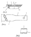
- One pipe section (2) has an end (3) drawn in by the measure of the sleeve and pipe wall thickness, with which it plunges into the opposite pipe section (5).
- the intermediate sleeve (11) is snugly fitted under tight contact.
- the intermediate sleeve (11) in turn is inserted in the pipe section (5) under tight, form-fitting guidance.
- the composite is secured in the longitudinal direction (10) by one or more retaining members (6). In the exemplary embodiments, only one restraining member is shown in each case.
- the retracted pipe end (3) has an essentially circular jacket opening (4) at the front end.
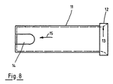
- the intermediate sleeve (11) on the other hand, has a jacket slot (14) at the same point, which is open to the front end side (seen in the plug-on direction (15) of the sleeve). As illustrated in FIG. 3, the two jacket openings (4, 14) are made to coincide when the intermediate sleeve (11) is attached.
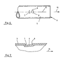
- the other pipe section (5) has a continuous cylindrical pipe contour in the area of the connection point (9).
- an embossing flap (6) is pressed in from the outside and protrudes inwards.
- the bottom of the flap (6) is longitudinally curved on the one hand and on the other hand extends obliquely inwards against the push-on direction (15) of the pipe section (5). This is achieved by two curved embossing impressions (7, 8) directed transversely to the longitudinal axis (10), of which the embossing impression (7), which is further away from the pipe end or the connection point (9), is deeper than the other embossing impression (8).
- the embossing impressions (7, 8) are spaced apart from one another in the longitudinal direction (10), but the flap region lying between them is also lowered somewhat.
- the embossing flap (6) is given an essentially circular shape corresponding to the jacket opening (4), while remaining connected to the tubular jacket on all sides.
- the intermediate sleeve (11) is first pushed onto the retracted end (3) as far as it will go and both parts are then inserted into the pipe section (5) so that the tab (6) passes through the jacket slot (14) of the intermediate sleeve slides and engages in the jacket opening (4) of the retracted end (3).
- the flap bottom on the embossing impression (8) is lowered just enough that it extends over the retracted end (3) and can slide through the slot (14) without getting caught on the face.
- the slanted position of the rag bottom makes it easier to unplug it and at the same time an inseparable bond is achieved.
- the downward flap end enters the jacket opening (4) so deeply that it blocks against a pull-out movement.
- the embossing flap (6) can slide somewhat resiliently when it is plugged onto the retracted end (3), but cannot deflect when it is removed.
- the intermediate sleeve (11) has a collar (12) projecting radially up to the level of the outer contour of the pipe section (5).
- the latter has on the inside a run-up slope (13) which is adapted to the tendency of the pipe section (2) to draw in.
- the waistband width also corresponds approximately to the length of the bevel.
- the outer contour of the pipe section (5) merges almost seamlessly into the outer contour of the other pipe section (2) via the collar (12).
- the pipe sections (2) can have a retracted end (3) on both ends, while the other pipe sections (5) only show receiving openings.
- the pipe sections (2) can also have a receiving opening on one side and a retracted end (3) on the other side. The design of the other pipe sections (5) then changes accordingly.
- the pipe sections (2, 5) do not have to be continuously hollow, but can also have solid areas.
- a piece of pipe can also have a corresponding widening.
- embossing flaps punching flaps or combination forms can also be used.
- the cross-sectional design of the pipe sections can be selected as desired and can also be oval or polygonal, for example, instead of the cylindrical shape shown.
Landscapes
- Engineering & Computer Science (AREA)
- Architecture (AREA)
- General Engineering & Computer Science (AREA)
- Physics & Mathematics (AREA)
- Electromagnetism (AREA)
- Civil Engineering (AREA)
- Structural Engineering (AREA)
- Mechanical Engineering (AREA)
- Quick-Acting Or Multi-Walled Pipe Joints (AREA)
- Mutual Connection Of Rods And Tubes (AREA)
- Rigid Pipes And Flexible Pipes (AREA)
- Joints That Cut Off Fluids, And Hose Joints (AREA)
Claims (11)
Applications Claiming Priority (2)
| Application Number | Priority Date | Filing Date | Title |
|---|---|---|---|
| DE8803245U | 1988-03-10 | ||
| DE8803245U DE8803245U1 (de) | 1988-03-10 | 1988-03-10 | Rohr |
Publications (2)
| Publication Number | Publication Date |
|---|---|
| EP0332209A1 EP0332209A1 (fr) | 1989-09-13 |
| EP0332209B1 true EP0332209B1 (fr) | 1991-10-16 |
Family
ID=6821688
Family Applications (1)
| Application Number | Title | Priority Date | Filing Date |
|---|---|---|---|
| EP89104293A Expired - Lifetime EP0332209B1 (fr) | 1988-03-10 | 1989-03-10 | Tube |
Country Status (3)
| Country | Link |
|---|---|
| EP (1) | EP0332209B1 (fr) |
| DE (2) | DE8803245U1 (fr) |
| ES (1) | ES2025827T3 (fr) |
Families Citing this family (5)
| Publication number | Priority date | Publication date | Assignee | Title |
|---|---|---|---|---|
| DE4404863A1 (de) * | 1994-02-16 | 1995-08-17 | Schneegans Gmbh | Stoßdämpfer |
| FR2729721B1 (fr) * | 1995-01-20 | 1997-04-11 | Gibault Lagache Architectes Et | Dispositif de fixation a une paroi de support d'un element destine par exemple a porter des articles presentes dans un stand d'exposition |
| KR200182863Y1 (ko) | 1999-12-27 | 2000-05-15 | 라제건 | 텐트폴의 연결구조 |
| DE102014006404A1 (de) * | 2014-05-05 | 2015-11-05 | Carl Freudenberg Kg | Rohr |
| EP3902732B1 (fr) | 2018-12-28 | 2025-03-19 | Uni-Troll Europe Aps | Système d'accouplement |
Family Cites Families (17)
| Publication number | Priority date | Publication date | Assignee | Title |
|---|---|---|---|---|
| FR880535A (fr) * | 1943-04-03 | |||
| US1703037A (en) * | 1926-05-27 | 1929-02-19 | Mannesmannrohrenwerke | Method of joining tubular members |
| DE958701C (de) * | 1954-03-06 | 1957-02-21 | Hilgers A G | Zug- und druckfeste Rohrverbindung, insbesondere fuer Baukonstruktionen |
| FR1131219A (fr) * | 1955-09-09 | 1957-02-19 | Organe d'assemblage pour éléments tubulaires et tréteau constitué par de tels organes associés à des éléments de tubes | |
| AT210688B (de) * | 1957-09-19 | 1960-08-25 | Karl Ing Bengesser | Kupplungsvorrichtung |
| CH405961A (de) * | 1963-12-04 | 1966-01-15 | Fickler Hans | Gepäckträger zur Befestigung am Dache eines Automobils |
| DE2725921A1 (de) * | 1977-06-08 | 1978-12-21 | Adolff Emil Fa | Mehrteilige hohlstange |
| DE2806764C3 (de) * | 1978-02-17 | 1980-10-30 | Quadro Spiel- Und Sportgeraete Gmbh, 7410 Reutlingen | Steckverbindung |
| FR2421252A1 (fr) * | 1978-03-29 | 1979-10-26 | Somefran | Dispositif de raccordement de deux elements tubulaires, et elements d'echafaudage correspondants a cadres prefabriques |
| DE2942457A1 (de) * | 1979-10-20 | 1981-04-30 | Willy 7750 Konstanz Hahn | Stufenfoermig aus einem stueck verjuengter hohltraeger - rohr |
| IT7923322U1 (it) * | 1979-12-01 | 1981-06-01 | Savatarelli Pietro | Ponteggio tubolare metallico pieghevole |
| DE8227371U1 (de) * | 1982-09-29 | 1983-01-20 | Eduard Kronenberg GmbH & Co, 5650 Solingen | Beschlag fuer geradlinige stossverbindung von hohlprofilen |
| DE3525402A1 (de) * | 1985-07-16 | 1987-01-29 | Thyssen Plastik Anger Kg | Schnellverbinder |
| DE8520545U1 (de) * | 1985-07-16 | 1988-04-07 | Thyssen Plastik Anger KG, 8000 München | Schnellverbinder |
| DE3526729A1 (de) * | 1985-07-26 | 1987-02-05 | Hueppe Gmbh | Verbindung zwischen zwei hohlprofilen, insbesondere fuer eine duschabtrennung |
| DE8528924U1 (de) * | 1985-10-11 | 1985-12-12 | Anneliese Mertes GmbH, 5180 Eschweiler | Anschlußelement für rohrförmige Bauteile |
| EP0233387A1 (fr) * | 1986-01-20 | 1987-08-26 | Silk Cut Flowers Limited | Noeud d'assemblage |
-
1988
- 1988-03-10 DE DE8803245U patent/DE8803245U1/de not_active Expired
-
1989
- 1989-03-10 DE DE8989104293T patent/DE58900368D1/de not_active Expired - Lifetime
- 1989-03-10 ES ES198989104293T patent/ES2025827T3/es not_active Expired - Lifetime
- 1989-03-10 EP EP89104293A patent/EP0332209B1/fr not_active Expired - Lifetime
Also Published As
| Publication number | Publication date |
|---|---|
| EP0332209A1 (fr) | 1989-09-13 |
| ES2025827T3 (es) | 1992-04-01 |
| DE8803245U1 (de) | 1989-05-24 |
| DE58900368D1 (de) | 1991-11-21 |
Similar Documents
| Publication | Publication Date | Title |
|---|---|---|
| DE60206570T2 (de) | Schwenkbolzenverbindung zwischen zwei Teilen | |
| EP0462257B1 (fr) | Mandrin de serrage pour des extremites polygonales de tiges d'outils | |
| DE29703876U1 (de) | Auszugsleiter | |
| DE2905848C2 (fr) | ||
| DE1784533B2 (de) | Verbindung eines stabs mit einem vierkantrohr | |
| EP3135574B1 (fr) | Couplage | |
| EP0332209B1 (fr) | Tube | |
| WO1987004674A1 (fr) | Dispositif pour le reglage graduel en hauteur d'un point de fixation ou de renvoi pour une ceinture de securite ou similaire | |
| DE69400606T2 (de) | Türverstärkung für Kraftfahrzeug | |
| DE20005627U1 (de) | Rohrelement | |
| DE3111930A1 (de) | Gestaenge-verbindungsklemme | |
| LU82991A1 (de) | Spanndrahthalter fuer zaeune | |
| DE1931390A1 (de) | Sicherheitslenksaeule | |
| CH690732A5 (de) | Schalungshilfsteil für eine Gewindehülse. | |
| DE2025266C3 (de) | Vorrichtung zum Verbinden von axial gestoßenen Stützenteilen einer Metallkonstruktion | |
| DE8431585U1 (de) | Kabelband mit integrierter Befestigungshülse zur Halterung auf einem Gewindebolzen | |
| EP2046205A1 (fr) | Dispositif médical | |
| DE102013110983A1 (de) | Verbindungssystem | |
| AT268594B (de) | Verbindungsvorrichtung | |
| DE69404908T2 (de) | Scheibenwischer mit gelenkig verbundenen Elementen | |
| DE2147286C3 (de) | Ausziehbarer Unterlenker für Dre'ipunktgerätekupplungen | |
| DE3309055A1 (de) | Verriegelungssystem | |
| DE4241771A1 (de) | Dachreling für Kraftfahrzeuge | |
| DE4211959A1 (de) | Rohrverbindung | |
| DE29815824U1 (de) | Arretierelement zur lösbaren Arretierung einer Verbindung, insbesondere zweier rohrförmiger Bauteile eines Kinderfahrzeugs |
Legal Events
| Date | Code | Title | Description |
|---|---|---|---|
| PUAI | Public reference made under article 153(3) epc to a published international application that has entered the european phase |
Free format text: ORIGINAL CODE: 0009012 |
|
| AK | Designated contracting states |
Kind code of ref document: A1 Designated state(s): DE ES FR GB IT NL |
|
| 17P | Request for examination filed |
Effective date: 19891109 |
|
| 17Q | First examination report despatched |
Effective date: 19900809 |
|
| GRAA | (expected) grant |
Free format text: ORIGINAL CODE: 0009210 |
|
| AK | Designated contracting states |
Kind code of ref document: B1 Designated state(s): DE ES FR GB IT NL |
|
| GBT | Gb: translation of ep patent filed (gb section 77(6)(a)/1977) | ||
| REF | Corresponds to: |
Ref document number: 58900368 Country of ref document: DE Date of ref document: 19911121 |
|
| ET | Fr: translation filed | ||
| ITF | It: translation for a ep patent filed | ||
| PGFP | Annual fee paid to national office [announced via postgrant information from national office to epo] |
Ref country code: FR Payment date: 19920213 Year of fee payment: 4 |
|
| PGFP | Annual fee paid to national office [announced via postgrant information from national office to epo] |
Ref country code: ES Payment date: 19920325 Year of fee payment: 4 |
|
| PGFP | Annual fee paid to national office [announced via postgrant information from national office to epo] |
Ref country code: NL Payment date: 19920331 Year of fee payment: 4 |
|
| REG | Reference to a national code |
Ref country code: ES Ref legal event code: FG2A Ref document number: 2025827 Country of ref document: ES Kind code of ref document: T3 |
|
| PLBE | No opposition filed within time limit |
Free format text: ORIGINAL CODE: 0009261 |
|
| STAA | Information on the status of an ep patent application or granted ep patent |
Free format text: STATUS: NO OPPOSITION FILED WITHIN TIME LIMIT |
|
| 26N | No opposition filed | ||
| PG25 | Lapsed in a contracting state [announced via postgrant information from national office to epo] |
Ref country code: GB Effective date: 19930310 |
|
| PG25 | Lapsed in a contracting state [announced via postgrant information from national office to epo] |
Ref country code: ES Free format text: LAPSE BECAUSE OF NON-PAYMENT OF DUE FEES Effective date: 19930311 |
|
| PG25 | Lapsed in a contracting state [announced via postgrant information from national office to epo] |
Ref country code: NL Effective date: 19931001 |
|
| GBPC | Gb: european patent ceased through non-payment of renewal fee |
Effective date: 19930310 |
|
| NLV4 | Nl: lapsed or anulled due to non-payment of the annual fee | ||
| PG25 | Lapsed in a contracting state [announced via postgrant information from national office to epo] |
Ref country code: FR Effective date: 19931130 |
|
| REG | Reference to a national code |
Ref country code: FR Ref legal event code: ST |
|
| PGFP | Annual fee paid to national office [announced via postgrant information from national office to epo] |
Ref country code: DE Payment date: 19940311 Year of fee payment: 6 |
|
| PG25 | Lapsed in a contracting state [announced via postgrant information from national office to epo] |
Ref country code: DE Effective date: 19951201 |
|
| REG | Reference to a national code |
Ref country code: ES Ref legal event code: FD2A Effective date: 19990301 |
|
| PG25 | Lapsed in a contracting state [announced via postgrant information from national office to epo] |
Ref country code: IT Free format text: LAPSE BECAUSE OF NON-PAYMENT OF DUE FEES Effective date: 20050310 |