EP0332282A2 - Luftfilter mit aufgeladenem, plissiertem Medium - Google Patents
Luftfilter mit aufgeladenem, plissiertem Medium Download PDFInfo
- Publication number
- EP0332282A2 EP0332282A2 EP89200614A EP89200614A EP0332282A2 EP 0332282 A2 EP0332282 A2 EP 0332282A2 EP 89200614 A EP89200614 A EP 89200614A EP 89200614 A EP89200614 A EP 89200614A EP 0332282 A2 EP0332282 A2 EP 0332282A2
- Authority
- EP
- European Patent Office
- Prior art keywords
- filter
- media
- charging
- air
- tray
- Prior art date
- Legal status (The legal status is an assumption and is not a legal conclusion. Google has not performed a legal analysis and makes no representation as to the accuracy of the status listed.)
- Withdrawn
Links
Images


Classifications
-
- B—PERFORMING OPERATIONS; TRANSPORTING
- B03—SEPARATION OF SOLID MATERIALS USING LIQUIDS OR USING PNEUMATIC TABLES OR JIGS; MAGNETIC OR ELECTROSTATIC SEPARATION OF SOLID MATERIALS FROM SOLID MATERIALS OR FLUIDS; SEPARATION BY HIGH-VOLTAGE ELECTRIC FIELDS
- B03C—MAGNETIC OR ELECTROSTATIC SEPARATION OF SOLID MATERIALS FROM SOLID MATERIALS OR FLUIDS; SEPARATION BY HIGH-VOLTAGE ELECTRIC FIELDS
- B03C3/00—Separating dispersed particles from gases or vapour, e.g. air, by electrostatic effect
- B03C3/02—Plant or installations having external electricity supply
- B03C3/04—Plant or installations having external electricity supply dry type
- B03C3/14—Plant or installations having external electricity supply dry type characterised by the additional use of mechanical effects, e.g. gravity
- B03C3/155—Filtration
-
- B—PERFORMING OPERATIONS; TRANSPORTING
- B03—SEPARATION OF SOLID MATERIALS USING LIQUIDS OR USING PNEUMATIC TABLES OR JIGS; MAGNETIC OR ELECTROSTATIC SEPARATION OF SOLID MATERIALS FROM SOLID MATERIALS OR FLUIDS; SEPARATION BY HIGH-VOLTAGE ELECTRIC FIELDS
- B03C—MAGNETIC OR ELECTROSTATIC SEPARATION OF SOLID MATERIALS FROM SOLID MATERIALS OR FLUIDS; SEPARATION BY HIGH-VOLTAGE ELECTRIC FIELDS
- B03C3/00—Separating dispersed particles from gases or vapour, e.g. air, by electrostatic effect
- B03C3/32—Transportable units, e.g. for cleaning room air
Definitions
- the present invention relates to electrostatic air filtration systems of the charged media type and in particular to a novel construction for charged media type air filters wherein contact between the fibrous filter pads and the charging media of the filter is minimized or eliminated, resulting in a dramatic increase in the efficiency of the filter.
- a number of air filter constructions are disclosed which are adaptable to use as disposable cartridge type filters, as well as a novel air filter cartridge frame and a desk top air filter unit.
- Electrostatic air filtration systems of the charged media type are well known. Traditionally, these systems comprise a metallic screen charged with a high voltage/low amperage current which is sandwiched between a pair of fibrous filter pads and a pair of grounded metallic screens that cover each side of the filter sandwich.
- United States Patent No. 4,549,887 and Canadian Patent No. 1,175,754 describe charged media type air filters constructed in this fashion. Although these electrostatic air filters are much more efficient than passive air filtration systems, they have a feature in their design which can impair their efficiency. The close contact of the filter's charging screens with the fibrous filter pads can lead to a considerable voltage drop on the high voltage screen due to conduction across the filter media. This is especially true after the filter media has become soiled with dust and other airborne filtrates.
- a voltage drop of up to 60% of the input voltage has been observed on the charged screens of these filters. This voltage drop affects the strength of the electrostatic field created within the fibrous filter pads and thereby impairs the efficiency of the filter.
- the present invention overcomes this problem with a novel filter construction wherein contact between the fibrous filter media and at least one of the filter's charging screens is minimized or completely eliminated, enabling the maintenance of an electrostatic field of full or near full potential regardless of the contamination level of the filter media, thus providing an air filtration system of the charged media type which is dramatically more efficient than those of the prior art. It has also been established that an efficient filter can be produced with only two charging screens and a single filter pad, providing a more economical filter construction.
- the present invention provides an electrostatic air filtration system of the charged media type comprising, in combination, electrically conductive charging media having passageways therethrough to allow for the substantially free passage of air, the charging media being in one or more pairs, the media of each pair located in opposed parallel spaced-apart relationship with a fibrous filter pad disposed between each adjacent pair of charging media. Conduction across the filter pads is reduced by either corrugating the filter pads or providing insulating spacers to separate each filter pad from one or both of the adjacent charging media.
- the charging media of the air filter are connected alternately to the respective poles of a high voltage power source to create an electrostatic field which polarizes the fibers of the filter media.
- An appropriately constructed frame supports the charging media, the filter media and the insulating spacers in the relation described within an air handling system.
- Fig. 1 illustrates a disposable filter cartridge according to the invention.
- the cartridge comprises an insulating frame 1 which houses a charging medium 2 on the top surface and a charging medium 3 on the bottom surface of the cartridge.
- Insulating frame 1 is preferably constructed of cardboard, although plastics or other non conductive materials are also suitable for this application.
- Charging media 2 and 3 are traditionally constructed of woven metallic screen, however, expanded metallic mesh has proven to be equally effective and more economical and any electrically conductive construction which provides for the free passage of air is suitable for the charging media.
- a corrugated fibrous filter pad 4 is disposed between the two charging media 2 and 3.
- Fibrous filter pad 4 is traditionally constructed of fiberglass but most dielectric fibers, including synthetic fibers such as polyester and blends of synthetic and natural fibers such as polyester and cotton have also been established to be effective filter mediums.
- a high voltage power jack 5 (see Fig. 23 for details) provides a connection between a high voltage power source (not illustrated) and the charging media 2 and 3 of the cartridge.
- the supply of power to the charging media can, of course, be arranged in any number of alternate ways well known in the art.
- the generally accepted practice is that charging medium 2 is grounded and that charging medium 3 is connected to a high voltage power of the order of 6 to 10 KV.
- Fig. 2 shows a cross section of the filter cartridge of Fig. 1.
- the connection of charging media 2 and 3 with high voltage power jack 5 is also illustrated. It may be noted that high voltage medium 3 does not contact the cardboard frame 1 of the cartridge filter. This is to prevent arcing between the high voltage medium 3 and the frame 1 should the frame 1 become damp or soiled enough to become electrically conductive.
- FIG. 3 A variation of the filter cartridge of Fig. 2 is illustrated in Fig. 3.
- the charging media 2 and 3 are latitudinally crimped to form partial corrugations which conform with the corrugations of the filter medium, lending rigidity to the filter cartridge.
- the charging media are still adequately separated to significantly reduce conduction across a soiled filter pad while providing a more rugged replacement filter cartridge.
- the disposable filter cartridges of Figs. 1 and 3 are supported in an air handling system by the filter cartridge frame of Fig. 22, as will become apparent.
- Fig. 4 and 5 show a novel construction for an efficient and very economical disposable filter cartridge.
- a single charging medium 6 and a single fibrous filter pad 7 are corrugated in unison and provided with a disposable frame 8.
- This disposable filter cartridge is supported in an air handling system by the filter cartridge frame shown in Figs. 15 and 16, the construction and operation of which will be explained in detail hereinafter.
- Charging medium 6 serves as the grounded medium of the filter and is provided with a metallic foil ground connection 9, the function of which will also be explained hereinafter.
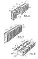
- Figs. 6 and 7 illustrate two more disposable filter constructions according to the invention.
- charging media 10 and 11 are disposed on each side of a fibrous filter pad 12.
- Spacers 13 maintain an air space 14 between charging media 11 and filter pad 12.
- Air space 14 prevents electrical conduction across the filter pad and the resulting loss of potential in the filter's electrostatic field.
- the embodiment shown in Fig. 7 employs insulating spacers 13 between fibrous filter pad 12 and both charging media 10 and 11.
- These filter constructions may also be provided with cardboard frames, not illustrated for clarity, and power supply jacks such as the one shown in Fig. 23, or some alternate method known in the art of connecting the charging media to a high voltage power source.
- Filter cartridge constructions of this type are also supported in an air handling system by a filter cartridge frame such as the one shown in Fig. 22.
- FIG. 8 Another embodiment of a filter structure is shown in Fig. 8 wherein a corrugated filter pad 21 and a flat filter pad 22 are used in combination to provide a progressive filter which is more efficient than the filters heretofore described.
- the upstream filter pad (either pad 21 or 22) is preferably of a coarser mat than the downstream filter pad, however, this is not mandatory.
- the central charging media 17 is traditionally connected to the high voltage pole of high voltage power supply jack 23 and the outside charging media 18 are traditionally connected to the neutral or grounded pole of the power supply jack 23 for security against shock. It has been established, however, that for purposes of functionality, connecting charging medium 18 to the high voltage power source and charging medium 17 to the neutral pole is equally effective. Spacers 19 separate charging medium 18 from flat filter pad 20 to prevent electrical discharge across the pad.
- Cardboard frame 20 is preferably continuous across the top and bottom of the filter cartridge but is shown cut away for clarity.
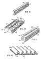
- FIG. 9 an alternate economical filter cartridge construction is shown.
- This filter cartridge consists of a single charging medium 15 and a single fibrous filter pad 16.
- This filter cartridge construction is generally not provided with a cardboard frame. It may be supported in an air handling system by the filter cartridge frame illustrated in Fig. 15 or the desk top air filter unit illustrated in Figs. 19 through 21.
- Charging medium 15 of this filter cartridge serves as the grounded medium of an air filter.
- charging medium 15 is made to project slightly beyond the edges of the filter pad 16 so that it contacts the edge of the grounded metallic frame 51 of cartridge filter support frame 50, as will be explained in reference to Fig. 15.
- Fig. 10 shows a further embodiment of a progressive filter cartridge similar to that shown in Fig. 8.
- two corrugated filter pads 26 are disposed between a central charging medium 24 and two outside charging media 25.
- the upstream filter pad is preferably a coarser mat than the downstream filter pad although this is optional.
- the two corrugated filter pads 26 provide more filtering surface and, therefore, less air pressure drop across the filter than occurs with flat filter pads.
- the charging media are connected to the respective poles of high voltage power supply jack 28 in the manner described.
- Cardboard frame 27 is also preferably continuous across the top and bottom of the filter cartridge although it is only partially depicted for clarity.
- FIG. 11 One further variation of the filter structures of Figs 9 and 10 is depicted in Fig. 11.
- two flat fibrous filter pads 30 are disposed between two outside charging media 29.
- a central charging medium 28 is insulated from each filter pad 30 by opposing insulating spacers 31 to prevent electrical conduction across filter pads 30.
- a cardboard frame and high voltage power jack may also be provided in a manner previously described but are not illustrated for clarity.
- the filter cartridges shown in Figs. 9, 10, and 11 are supported in an air handling system using a cartridge filter frame similar to the one depicted in Fig. 22.
- Fig. 12 depicts a further embodiment of a disposable filter cartridge wherein a corrugated filter pad 32 is provided with a charging medium 33 which is constructed with latitudinal spikes 34 which interleave the corrugations of the filter pad 32.
- the charging medium 33 serves as a frame for the disposable cartridge and filter pad 32 is bonded to the charging medium 33 with an appropriate adhesive.
- This disposable cartridge is used in conjunction with the disposable cartridge filter frame of Fig. 15. It is inserted into filter cartridge frame 50 in an orientation upside down to the illustration of Fig. 12 so that the fibrous filter pad 32 is adjacent the insulating spacers 52 of cartridge filter frame 50 (Fig. 15).
- charging medium 33 Because of interleaved spikes 34 of the charging medium 33, an enhanced electrostatic field is created within and around corrugated filter pad 32, rendering this embodiment particularly useful where very fine airborne contaminants must be removed by an air handling system.
- the upturned ends of charging medium 33 contact the metal frame 51 of the cartridge filter frame 50 (see Fig. 15) when installed in the cartridge filter frame, providing grounding contact for the charging medium 33.
- Figs. 13 and 14 illustrate further embodiments of filter structures according to the invention.
- the filter cartridge shown in cross section in Fig. 13 comprises two charging medium 35 and 36 and a fibrous filter pad 37.
- Filter pad 37 is separated from charging medium 35 by insulating spacers 38.
- Spacers 38 are affixed to the disposable cardboard frame 39 of the filter cartridge in the pattern illustrated to support the filter elements in the corrugated configuration shown.
- This structure provides an air filter with an increased surface area and, therefore, less air pressure drop across the filter than the traditional flat filter pads of the prior art.
- Charging medium 35 and 36 are connected to a high voltage power source in any order in a manner already described and well known in the art.
- a similar disposable filter cartridge structure which provides either a graduated filter or a double filter of the corrugated type.
- the outside surfaces of the corrugated filter pads are covered by charging medium 40 and 41 and a central charging medium 42 is also provided.
- Two fibrous filter pads 43 and 44 are disposed on either side of the central charging medium 42 and separated therefrom by opposing pairs of insulating spacers 45. Spacers 45 are attached to the cardboard filter cartridge frame 46 in the pattern illustrated to support the filter elements in the corrugated relation shown.
- the upstream filter pad, 43 or 44 is preferably of a coarser mat than the downstream filter pad, however, this is optional.
- Filter cartridge frame 46 is provided with a high voltage power jack 47 and connected to the charging medium as illustrated, the central charging medium 42 being preferably connected to the high voltage pole of power jack 47 for reasons of security against shock.
- the filter cartridge shown in Figs. 13 and 14 are supported in an air handling system using a filter cartridge frame similar to the frame of Fig. 22.
- FIG. 15 shows a filter cartridge support frame according to the invention and an expanded view of the filter cartridge of Figs. 4 and 5.
- Filter cartridge support frame 50 comprises a metallic frame 51, a charging medium 53 attached to but insulated from frame 51 in a manner known in the art, and insulating spacers 52 disposed at intervals across the surface of the charging medium 53.
- a high voltage power supply is housed in box 54A which is attached to one end of the frame 51 in this embodiment.
- the high voltage pole of the power supply 54 (see Fig. 16) is connected via insulated electrode 55 to charging medium 53.
- the neutral pole of the power supply 54 is connected to metallic frame 51.
- power supply 54 is connected to an electrical power source and the charging medium 53 is thereby charged with a high voltage/low amperage direct current of the order of 6 to 10 KV.
- the charging voltage is preset depending on the type of cartridge to be used with filter cartridge frame 50. In general, the thicker the filter pad of a cartridge, and consequently the more distanced the charging medium 53 on the bottom of the filter cartridge support frame 50 and the charging medium 6 of the filter cartridge, the higher the voltage required on charging medium 53.
- Fig. 16 shows in detail a portion of the cartridge filter support frame of Fig. 15, illustrating the construction of the power supply 54 and an optional media charging power interrupter switch 58.
- Power supply 54 is shielded in a protective box 54A which is supported by a projecting lip 56 which extends from a lower edge of frame 51.
- Box 54A is provided with an electrical power supply jack 59.
- the positive pole of jack 59 is connected to the positive input pole of power supply 54.
- the neutral pole of the jack 59 is connected to frame 51 or box 54A which is electrically continuous with the frame 51.
- the neutral pole of power supply 54 is connected to the connector end of a resilient switch member 58.
- Switch member 58 is retained in a hole 59 in frame 51 by a frictionally engaging mounting 57 (Figs.
- Switch 58 is insulated from mounting 57.
- the cardboard frame 8 of the filter cartridge forces the resilient switch 58 into contact with the metallic frame member 51 of the cartridge filter support frame 50, completing the power supply circuit and providing high voltage power flow through electrode 55 to the charging media 53.
- grounding connector 9 on the cardboard filter frame 8 contacts filter frame 51, grounding charging media 6 and completing the circuitry required to create an electrostatic field in an around the filter pad 7.
- Switch 58 is optional and is not installed if a soft sided filter cartridge such as the filter cartridge of Fig. 9 is to be used in filter cartridge support frame 50.
- Fig. 19 shows a novel desk top air filter unit, generally referred to by reference 59, in accordance with the invention.
- a two part housing with a top part 60 and a base part 61 encloses the other functional parts of the unit.
- a standard power cord 72 supplies AC power to the unit.
- housings 60 and 61 are provided with louvres 70 and 71 respectively to permit the passage of air through the filter unit.
- a fan 62A is driven by a motor 62B which is powered by electric power cord 72. Air forced through the filter by fan 62A must pass through the electronic filter structure which comprises an inside high voltage charging medium 64 that is supported away from filter pad 66 by upright insulating supports 63.
- the grounded charging medium 65 is bonded to the filter pad 66 to form a disposable filter cartridge of the type shown in Fig. 9. Fins 67 which project from the inside surface of the housing part 60 serve to retain the cartridge filter formed by filter pad 66 and charging medium 65 in close proximity with upright supports 63 and charging medium 64. Grounded charging medium 65 contacts a grounding shoe 68 which is attached to the neutral line of power cord 72. High voltage power supply 69 is attached to the positive line of power cord 72. The high voltage power supply provides a high voltage current of the order of 6 to 10 KV to charging medium 64 which polarizes the fibers of the filter pad 66 and any particles in the air forced through the filter pad by fan 62A.
- the polarized air contaminants are thereby strongly attracted to the fibers of the filter pad and most of the contaminants cling to the pad even though they are small enough to pass through the pad without obstruction.
- power cord 72 is unplugged, and the upper housing part 60 is removed to expose the interior of the unit.
- the disposable filter cartridge which comprises charging medium 65 and filter pad 66 bonded together as a unit is removed and a fresh filter cartridge is inserted. Once the filter cartridge is replaced with a fresh cartridge, the upper housing part 60 is replaced and the unit is again ready for use.
- Figs. 22 and 23 illustrate prior art devices used in conjunction with certain filter cartridge structures heretofore described.
- a filter cartridge support frame 80 is provided with a composite electrode which has a neutral pole 81 and a high voltage pole 82. Power is supplied to the high voltage electrode by a high voltage supply cable 83.
- Fig. 22 illustrates a cross sectional view of a high voltage power jack which is mounted on the filter cartridges so as to engage the high voltage electrode of the filter support frame 80 of Fig. 22 when the cartridges are inserted into the support frame.
- High voltage jack 85 is mounted in an end of a cardboard filter cartridge frame 84 and connected via positive lead 86 and negative lead 87 (see Fig. 23) to the charging media of the filter cartridge as required by the construction of the filter cartridge.
Landscapes
- Electrostatic Separation (AREA)
- Filtering Materials (AREA)
Applications Claiming Priority (2)
| Application Number | Priority Date | Filing Date | Title |
|---|---|---|---|
| CA561231 | 1988-03-11 | ||
| CA000561231A CA1319624C (en) | 1988-03-11 | 1988-03-11 | Pleated charged media air filter |
Publications (2)
| Publication Number | Publication Date |
|---|---|
| EP0332282A2 true EP0332282A2 (de) | 1989-09-13 |
| EP0332282A3 EP0332282A3 (de) | 1990-12-05 |
Family
ID=4137630
Family Applications (1)
| Application Number | Title | Priority Date | Filing Date |
|---|---|---|---|
| EP19890200614 Withdrawn EP0332282A3 (de) | 1988-03-11 | 1989-03-10 | Luftfilter mit aufgeladenem, plissiertem Medium |
Country Status (5)
| Country | Link |
|---|---|
| US (1) | US4978372A (de) |
| EP (1) | EP0332282A3 (de) |
| JP (1) | JP2856282B2 (de) |
| AU (1) | AU616740B2 (de) |
| CA (1) | CA1319624C (de) |
Cited By (5)
| Publication number | Priority date | Publication date | Assignee | Title |
|---|---|---|---|---|
| EP0443254A1 (de) * | 1990-02-20 | 1991-08-28 | The Scott Fetzer Company | Elektrostatisches Filtrieren von Stoffen |
| US5376168A (en) * | 1990-02-20 | 1994-12-27 | The L. D. Kichler Co. | Electrostatic particle filtration |
| US5405434A (en) * | 1990-02-20 | 1995-04-11 | The Scott Fetzer Company | Electrostatic particle filtration |
| EP1038568A1 (de) * | 1999-03-22 | 2000-09-27 | Valeo | Vorrichtung zur Filtration insbesondere zur Reinigung von Luft für die Belüftung und/oder die Heizung und/oder die Klimatisierung von Räumen oder von Innenräumen von Automobilen |
| IT201600105849A1 (it) * | 2016-10-20 | 2018-04-20 | Bmc Srl | Metodo di produzione di un filtro aria elettrificato per un sistema di aspirazione di un propulsore di un veicolo |
Families Citing this family (74)
| Publication number | Priority date | Publication date | Assignee | Title |
|---|---|---|---|---|
| CA1314237C (en) * | 1988-11-01 | 1993-03-09 | William E. Pick | Charging element having odour absorbing properties for an electrostatic air filter |
| US5330722A (en) * | 1991-02-27 | 1994-07-19 | William E. Pick | Germicidal air filter |
| US5647890A (en) * | 1991-12-11 | 1997-07-15 | Yamamoto; Yujiro | Filter apparatus with induced voltage electrode and method |
| US5540761A (en) * | 1991-12-11 | 1996-07-30 | Yamamoto; Yujiro | Filter for particulate materials in gaseous fluids |
| JP3388740B2 (ja) | 1991-12-11 | 2003-03-24 | ヤマモト,ユージロー | ガス流体中の微粒子を捕獲するためのフィルタおよびこのフィルタを用いてガス流体中の微粒子を捕獲するための方法 |
| USD340509S (en) | 1991-12-19 | 1993-10-19 | Honeywell Inc. | Ceiling mounted electronic air cleaner enclosure |
| US5330559A (en) * | 1992-08-11 | 1994-07-19 | United Air Specialists, Inc. | Method and apparatus for electrostatically cleaning particulates from air |
| US5474599A (en) * | 1992-08-11 | 1995-12-12 | United Air Specialists, Inc. | Apparatus for electrostatically cleaning particulates from air |
| US5549735C1 (en) * | 1994-06-09 | 2001-08-14 | Coppom Technologies | Electrostatic fibrous filter |
| US5630866A (en) * | 1995-07-28 | 1997-05-20 | Gregg; Lloyd M. | Static electricity exhaust treatment device |
| US5614002A (en) * | 1995-10-24 | 1997-03-25 | Chen; Tze L. | High voltage dust collecting panel |
| EP0921861B1 (de) * | 1996-07-25 | 2002-09-25 | Y2 Ultra-Filter, Inc. | Filtervorrichtung mit elektrode mit induzierte spannung |
| US6368391B1 (en) * | 2000-08-23 | 2002-04-09 | Healthway Products Company, Inc. | Electronically enhanced media air filtration system |
| US6056809A (en) * | 1996-10-18 | 2000-05-02 | Rick L. Chapman | High efficiency permanent air filter and method of manufacture |
| US5846302A (en) * | 1997-04-24 | 1998-12-08 | Aqua-Air Technologies, Inc. | Electrostatic air filter device |
| SE511329C2 (sv) * | 1997-08-06 | 1999-09-13 | Eurus Airtech Ab | Anordning för rening av luft |
| US7220295B2 (en) | 2003-05-14 | 2007-05-22 | Sharper Image Corporation | Electrode self-cleaning mechanisms with anti-arc guard for electro-kinetic air transporter-conditioner devices |
| US20030206837A1 (en) | 1998-11-05 | 2003-11-06 | Taylor Charles E. | Electro-kinetic air transporter and conditioner device with enhanced maintenance features and enhanced anti-microorganism capability |
| US7695690B2 (en) | 1998-11-05 | 2010-04-13 | Tessera, Inc. | Air treatment apparatus having multiple downstream electrodes |
| US7318856B2 (en) | 1998-11-05 | 2008-01-15 | Sharper Image Corporation | Air treatment apparatus having an electrode extending along an axis which is substantially perpendicular to an air flow path |
| US6544485B1 (en) | 2001-01-29 | 2003-04-08 | Sharper Image Corporation | Electro-kinetic device with enhanced anti-microorganism capability |
| US20050210902A1 (en) | 2004-02-18 | 2005-09-29 | Sharper Image Corporation | Electro-kinetic air transporter and/or conditioner devices with features for cleaning emitter electrodes |
| US6176977B1 (en) | 1998-11-05 | 2001-01-23 | Sharper Image Corporation | Electro-kinetic air transporter-conditioner |
| US6454839B1 (en) * | 1999-10-19 | 2002-09-24 | 3M Innovative Properties Company | Electrofiltration apparatus |
| US6497754B2 (en) * | 2001-04-04 | 2002-12-24 | Constantinos J. Joannou | Self ionizing pleated air filter system |
| US6660061B2 (en) | 2001-10-26 | 2003-12-09 | Battelle Memorial Institute | Vapor purification with self-cleaning filter |
| US6764533B2 (en) * | 2001-10-30 | 2004-07-20 | Joseph A. Liobiondo, Sr. | Electronic air filter assembly |
| FI113157B (fi) * | 2002-04-11 | 2004-03-15 | Lifa Iaq Ltd Oy | Sähkösuodatinrakenne |
| JP2004273315A (ja) * | 2003-03-10 | 2004-09-30 | Sharp Corp | イオン発生装置、空気調節装置および荷電装置 |
| US7405672B2 (en) | 2003-04-09 | 2008-07-29 | Sharper Image Corp. | Air treatment device having a sensor |
| US20050051420A1 (en) | 2003-09-05 | 2005-03-10 | Sharper Image Corporation | Electro-kinetic air transporter and conditioner devices with insulated driver electrodes |
| US7906080B1 (en) | 2003-09-05 | 2011-03-15 | Sharper Image Acquisition Llc | Air treatment apparatus having a liquid holder and a bipolar ionization device |
| US7724492B2 (en) | 2003-09-05 | 2010-05-25 | Tessera, Inc. | Emitter electrode having a strip shape |
| US7077890B2 (en) | 2003-09-05 | 2006-07-18 | Sharper Image Corporation | Electrostatic precipitators with insulated driver electrodes |
| US7517503B2 (en) | 2004-03-02 | 2009-04-14 | Sharper Image Acquisition Llc | Electro-kinetic air transporter and conditioner devices including pin-ring electrode configurations with driver electrode |
| SE0302691D0 (sv) * | 2003-10-13 | 2003-10-13 | Andrzej Loreth | Hybridpartikelfilter |
| US7025806B2 (en) * | 2003-11-25 | 2006-04-11 | Stri{dot over (o)}nAir, Inc. | Electrically enhanced air filtration with improved efficacy |
| US7097694B1 (en) | 2003-12-04 | 2006-08-29 | Fleetguard, Inc. | High performance, high efficiency filter |
| US7767169B2 (en) | 2003-12-11 | 2010-08-03 | Sharper Image Acquisition Llc | Electro-kinetic air transporter-conditioner system and method to oxidize volatile organic compounds |
| US7638104B2 (en) | 2004-03-02 | 2009-12-29 | Sharper Image Acquisition Llc | Air conditioner device including pin-ring electrode configurations with driver electrode |
| US20060016333A1 (en) | 2004-07-23 | 2006-01-26 | Sharper Image Corporation | Air conditioner device with removable driver electrodes |
| US7285155B2 (en) | 2004-07-23 | 2007-10-23 | Taylor Charles E | Air conditioner device with enhanced ion output production features |
| US7311762B2 (en) | 2004-07-23 | 2007-12-25 | Sharper Image Corporation | Air conditioner device with a removable driver electrode |
| US7258729B1 (en) * | 2004-08-04 | 2007-08-21 | Air Ion Devices Inc. | Electronic bi-polar electrostatic air cleaner |
| US7691186B2 (en) * | 2005-12-29 | 2010-04-06 | Environmental Management Confederation, Inc. | Conductive bead active field polarized media air cleaner |
| CA2635729C (en) * | 2005-12-29 | 2014-03-25 | Environmental Management Confederation, Inc. | Conductive bead for active field polarized media air cleaner |
| US8795601B2 (en) | 2005-12-29 | 2014-08-05 | Environmental Management Confederation, Inc. | Filter media for active field polarized media air cleaner |
| US8814994B2 (en) | 2005-12-29 | 2014-08-26 | Environmental Management Confederation, Inc. | Active field polarized media air cleaner |
| US7708813B2 (en) * | 2005-12-29 | 2010-05-04 | Environmental Management Confederation, Inc. | Filter media for active field polarized media air cleaner |
| US9789494B2 (en) * | 2005-12-29 | 2017-10-17 | Environmental Management Confederation, Inc. | Active field polarized media air cleaner |
| US8252097B2 (en) * | 2005-12-29 | 2012-08-28 | Environmental Management Confederation, Inc. | Distributed air cleaner system for enclosed electronic devices |
| US7686869B2 (en) * | 2005-12-29 | 2010-03-30 | Environmental Management Confederation, Inc. | Active field polarized media air cleaner |
| US7883572B2 (en) * | 2006-01-12 | 2011-02-08 | Camfil Ab | Cleanable dust filter comprising a zigzag pleated filter pack |
| US7833322B2 (en) | 2006-02-28 | 2010-11-16 | Sharper Image Acquisition Llc | Air treatment apparatus having a voltage control device responsive to current sensing |
| US7951229B2 (en) * | 2007-09-11 | 2011-05-31 | Columbus Industries, Inc. | Air filter formed from slit and expanded layers of electrostatically enhanced material |
| CN201249077Y (zh) * | 2008-04-15 | 2009-06-03 | 深圳市奇滨实业有限公司 | 空气净化机 |
| US8357233B2 (en) | 2009-03-20 | 2013-01-22 | Sik Leung Chan | Collector modules for devices for removing particles from a gas |
| US9943796B2 (en) * | 2009-03-26 | 2018-04-17 | Columbus Industries, Inc. | Multi layer pleatable filter medium |
| US8409336B2 (en) * | 2009-09-01 | 2013-04-02 | Hunter Fan Company | Air filter system |
| WO2012055110A1 (zh) * | 2010-10-29 | 2012-05-03 | 南京师范大学 | 一种单区板式高温静电除尘器 |
| US9579663B2 (en) * | 2011-05-24 | 2017-02-28 | Carrier Corporation | Detection of electrostatic filter for air filtration system |
| GB2496888A (en) * | 2011-11-25 | 2013-05-29 | Tri Air Developments Ltd | Non-thermal plasma cell |
| US11819792B2 (en) | 2014-11-14 | 2023-11-21 | Columbus Industries, Inc. | Bidirectional airflow filter |
| AU2016250247A1 (en) | 2015-04-14 | 2017-11-02 | Environmental Management Confederation, Inc. | Corrugated filtration media for polarizing air cleaner |
| US10168059B2 (en) * | 2015-09-11 | 2019-01-01 | Panasonic Intellectual Property Management Co., Ltd. | Filtering medium and air purifier |
| KR101801119B1 (ko) | 2015-12-03 | 2017-11-27 | 경북대학교 산학협력단 | 비열 플라즈마를 이용한 차량용 실내 공기 청정 장치 |
| MX2019000026A (es) * | 2016-06-24 | 2019-10-30 | K&N Eng Inc | Filtros de aire compuestos y metodos de los mismos. |
| KR102502180B1 (ko) | 2017-12-08 | 2023-02-21 | 삼성전자주식회사 | 필터 모듈 |
| JP2020110771A (ja) * | 2019-01-15 | 2020-07-27 | 株式会社豊田自動織機 | フィルタ装置 |
| KR102370630B1 (ko) * | 2019-11-18 | 2022-03-04 | 엘지전자 주식회사 | 공기정화용 필터 및 이를 포함하는 공기정화기 |
| CN112275449A (zh) * | 2020-10-14 | 2021-01-29 | 厚联环境科技(上海)有限公司 | 一种无源式蓄能使用的微静电滤芯及其使用方法 |
| EP4230298B1 (de) * | 2022-02-18 | 2025-01-29 | Hengst SE | Kabinenluftfilter mit polarisierung |
| CN115581791A (zh) * | 2022-10-14 | 2023-01-10 | 爱优特空气技术(上海)有限公司 | 一种抗高湿的微静电净化装置 |
| DE102024129640A1 (de) * | 2024-10-14 | 2026-04-16 | Hengst Se | Gas-Filtereinsatz |
Family Cites Families (12)
| Publication number | Priority date | Publication date | Assignee | Title |
|---|---|---|---|---|
| US2067822A (en) * | 1936-04-11 | 1937-01-12 | Joseph B Biederman | Mask for the prevention and relief of allergic respiratory complaints |
| US2297601A (en) * | 1940-09-03 | 1942-09-29 | American Air Filter Co | Electric gas cleaner |
| US2589463A (en) * | 1950-05-31 | 1952-03-18 | Westinghouse Electric Corp | Electrostatic precipitator |
| DE1226080B (de) * | 1954-05-29 | 1966-10-06 | American Air Filter Co | Luftfilterpatrone aus dielektrischem Material |
| US3073094A (en) * | 1960-05-23 | 1963-01-15 | Trion Inc | Electrostatic filter panel |
| US3438180A (en) * | 1965-12-28 | 1969-04-15 | Trane Co | Air-cleaning apparatus |
| US3509696A (en) * | 1967-10-18 | 1970-05-05 | Carrier Corp | Collector assembly for electrostatic air precipitators |
| US3763633A (en) * | 1971-02-09 | 1973-10-09 | C Soltis | Electrostatic air filter |
| US3999964A (en) * | 1975-03-28 | 1976-12-28 | Carrier Corporation | Electrostatic air cleaning apparatus |
| GB2110119B (en) * | 1981-10-12 | 1986-03-19 | Senichi Masuda | High efficiency electrostatic filter device |
| CA1175754A (en) * | 1983-01-04 | 1984-10-09 | Constantinos J. Joannou | Electronic air filter |
| US4853005A (en) * | 1985-10-09 | 1989-08-01 | American Filtrona Corporation | Electrically stimulated filter method and apparatus |
-
1988
- 1988-03-11 CA CA000561231A patent/CA1319624C/en not_active Expired - Lifetime
-
1989
- 1989-03-10 US US07/321,397 patent/US4978372A/en not_active Expired - Lifetime
- 1989-03-10 AU AU31234/89A patent/AU616740B2/en not_active Ceased
- 1989-03-10 EP EP19890200614 patent/EP0332282A3/de not_active Withdrawn
- 1989-03-13 JP JP6057189A patent/JP2856282B2/ja not_active Expired - Fee Related
Cited By (9)
| Publication number | Priority date | Publication date | Assignee | Title |
|---|---|---|---|---|
| EP0443254A1 (de) * | 1990-02-20 | 1991-08-28 | The Scott Fetzer Company | Elektrostatisches Filtrieren von Stoffen |
| US5143524A (en) * | 1990-02-20 | 1992-09-01 | The Scott Fetzer Company | Electrostatic particle filtration |
| US5376168A (en) * | 1990-02-20 | 1994-12-27 | The L. D. Kichler Co. | Electrostatic particle filtration |
| US5405434A (en) * | 1990-02-20 | 1995-04-11 | The Scott Fetzer Company | Electrostatic particle filtration |
| EP1038568A1 (de) * | 1999-03-22 | 2000-09-27 | Valeo | Vorrichtung zur Filtration insbesondere zur Reinigung von Luft für die Belüftung und/oder die Heizung und/oder die Klimatisierung von Räumen oder von Innenräumen von Automobilen |
| FR2791275A1 (fr) * | 1999-03-22 | 2000-09-29 | Valeo | Dispositif de filtration destine notamment a l'epuration de l'air pour l'aeration et/ou le chauffage et/ou la climatisation de locaux ou d'habitacles de vehicules automobiles |
| IT201600105849A1 (it) * | 2016-10-20 | 2018-04-20 | Bmc Srl | Metodo di produzione di un filtro aria elettrificato per un sistema di aspirazione di un propulsore di un veicolo |
| WO2018073806A1 (en) * | 2016-10-20 | 2018-04-26 | Bmc S.R.L. | Method for manufacturing an electrified air filter for an intake system of an engine of a vehicle |
| US11617978B2 (en) | 2016-10-20 | 2023-04-04 | Bmc S.R.L. | Method for manufacturing an electrified air filter for an intake system of an engine of a vehicle |
Also Published As
| Publication number | Publication date |
|---|---|
| AU616740B2 (en) | 1991-11-07 |
| CA1319624C (en) | 1993-06-29 |
| US4978372A (en) | 1990-12-18 |
| JP2856282B2 (ja) | 1999-02-10 |
| JPH01307463A (ja) | 1989-12-12 |
| AU3123489A (en) | 1989-09-14 |
| EP0332282A3 (de) | 1990-12-05 |
Similar Documents
| Publication | Publication Date | Title |
|---|---|---|
| US4978372A (en) | Pleated charged media air filter | |
| US4886526A (en) | Electronic air filtration system | |
| US4828586A (en) | Cartridge type electronic air filter | |
| CA1175754A (en) | Electronic air filter | |
| EP0114178B1 (de) | Apparat zur Luftreinigung | |
| JP6029860B2 (ja) | 電気集塵装置 | |
| US5474599A (en) | Apparatus for electrostatically cleaning particulates from air | |
| US6294004B1 (en) | Structures for electrostatic V-bank air filters | |
| US4940470A (en) | Single field ionizing electrically stimulated filter | |
| US20100326279A1 (en) | Active field polarized media air cleaner | |
| KR20180101844A (ko) | 전기집진장치 및 집진유닛의 제조방법 | |
| RU2396127C2 (ru) | Усовершенствованный воздухоочиститель на основе поляризуемого под действием электрического поля материала | |
| US2502560A (en) | Electrical gas cleaner unit | |
| EP4062993A1 (de) | Luftreinigungsfilter und luftreiniger damit | |
| EP0229857A1 (de) | Elektrostatischer Luftfilter | |
| US3685258A (en) | Electronic air purifier | |
| KR102723646B1 (ko) | 전기집진기 | |
| KR20190007307A (ko) | 공기청정기용 집진부 및 이의 제조방법 | |
| JPH0332712A (ja) | 空気清浄器用フィルター | |
| KR200156415Y1 (ko) | 전기집진장치 | |
| CN210187416U (zh) | 一种吸油烟机用净化装置 | |
| KR20210063571A (ko) | 공기 조화기 | |
| HK40109883A (zh) | 电集尘机 | |
| JPH0428425B2 (de) | ||
| JPH04310249A (ja) | 電気式エアフィルタを取付けた空気調和装置及び空気清浄機 |
Legal Events
| Date | Code | Title | Description |
|---|---|---|---|
| PUAI | Public reference made under article 153(3) epc to a published international application that has entered the european phase |
Free format text: ORIGINAL CODE: 0009012 |
|
| AK | Designated contracting states |
Kind code of ref document: A2 Designated state(s): AT BE DE FR GB IT NL SE |
|
| PUAL | Search report despatched |
Free format text: ORIGINAL CODE: 0009013 |
|
| AK | Designated contracting states |
Kind code of ref document: A3 Designated state(s): AT BE DE FR GB IT NL SE |
|
| 17P | Request for examination filed |
Effective date: 19910313 |
|
| 17Q | First examination report despatched |
Effective date: 19920320 |
|
| STAA | Information on the status of an ep patent application or granted ep patent |
Free format text: STATUS: THE APPLICATION IS DEEMED TO BE WITHDRAWN |
|
| 18D | Application deemed to be withdrawn |
Effective date: 19921001 |