EP0332355B1 - Saugflasche - Google Patents
Saugflasche Download PDFInfo
- Publication number
- EP0332355B1 EP0332355B1 EP89302171A EP89302171A EP0332355B1 EP 0332355 B1 EP0332355 B1 EP 0332355B1 EP 89302171 A EP89302171 A EP 89302171A EP 89302171 A EP89302171 A EP 89302171A EP 0332355 B1 EP0332355 B1 EP 0332355B1
- Authority
- EP
- European Patent Office
- Prior art keywords
- bottle
- case
- temperature
- assembly according
- alarm
- Prior art date
- Legal status (The legal status is an assumption and is not a legal conclusion. Google has not performed a legal analysis and makes no representation as to the accuracy of the status listed.)
- Expired - Lifetime
Links
- 230000000474 nursing effect Effects 0.000 title claims description 22
- 239000007788 liquid Substances 0.000 claims description 21
- 239000000758 substrate Substances 0.000 claims description 21
- 210000002445 nipple Anatomy 0.000 claims description 15
- 238000000034 method Methods 0.000 claims description 6
- 230000000295 complement effect Effects 0.000 claims description 2
- 230000005611 electricity Effects 0.000 claims description 2
- 230000008569 process Effects 0.000 claims description 2
- 239000004973 liquid crystal related substance Substances 0.000 description 17
- 239000008267 milk Substances 0.000 description 11
- 210000004080 milk Anatomy 0.000 description 11
- 235000013336 milk Nutrition 0.000 description 11
- 238000009835 boiling Methods 0.000 description 6
- 239000010409 thin film Substances 0.000 description 6
- 238000001514 detection method Methods 0.000 description 5
- 230000005855 radiation Effects 0.000 description 5
- 230000001954 sterilising effect Effects 0.000 description 5
- 230000009471 action Effects 0.000 description 4
- 230000008859 change Effects 0.000 description 3
- 239000000463 material Substances 0.000 description 3
- 238000007789 sealing Methods 0.000 description 3
- 230000005676 thermoelectric effect Effects 0.000 description 3
- PXHVJJICTQNCMI-UHFFFAOYSA-N Nickel Chemical compound [Ni] PXHVJJICTQNCMI-UHFFFAOYSA-N 0.000 description 2
- 238000005273 aeration Methods 0.000 description 2
- 230000015572 biosynthetic process Effects 0.000 description 2
- 239000013078 crystal Substances 0.000 description 2
- 230000006870 function Effects 0.000 description 2
- 229910052751 metal Inorganic materials 0.000 description 2
- 239000002184 metal Substances 0.000 description 2
- 238000004659 sterilization and disinfection Methods 0.000 description 2
- XLYOFNOQVPJJNP-UHFFFAOYSA-N water Substances O XLYOFNOQVPJJNP-UHFFFAOYSA-N 0.000 description 2
- 229910001006 Constantan Inorganic materials 0.000 description 1
- LFQSCWFLJHTTHZ-UHFFFAOYSA-N Ethanol Chemical compound CCO LFQSCWFLJHTTHZ-UHFFFAOYSA-N 0.000 description 1
- PWHULOQIROXLJO-UHFFFAOYSA-N Manganese Chemical compound [Mn] PWHULOQIROXLJO-UHFFFAOYSA-N 0.000 description 1
- 239000003990 capacitor Substances 0.000 description 1
- 229910017052 cobalt Inorganic materials 0.000 description 1
- 239000010941 cobalt Substances 0.000 description 1
- GUTLYIVDDKVIGB-UHFFFAOYSA-N cobalt atom Chemical compound [Co] GUTLYIVDDKVIGB-UHFFFAOYSA-N 0.000 description 1
- 230000000052 comparative effect Effects 0.000 description 1
- 239000004020 conductor Substances 0.000 description 1
- 239000000470 constituent Substances 0.000 description 1
- 238000001816 cooling Methods 0.000 description 1
- 230000007423 decrease Effects 0.000 description 1
- 230000007547 defect Effects 0.000 description 1
- 230000010259 detection of temperature stimulus Effects 0.000 description 1
- 230000002349 favourable effect Effects 0.000 description 1
- 239000011521 glass Substances 0.000 description 1
- 230000036541 health Effects 0.000 description 1
- 238000010438 heat treatment Methods 0.000 description 1
- 229910052748 manganese Inorganic materials 0.000 description 1
- 239000011572 manganese Substances 0.000 description 1
- 229910044991 metal oxide Inorganic materials 0.000 description 1
- 150000004706 metal oxides Chemical class 0.000 description 1
- 150000002739 metals Chemical class 0.000 description 1
- 229910052759 nickel Inorganic materials 0.000 description 1
- 239000003973 paint Substances 0.000 description 1
- 239000004033 plastic Substances 0.000 description 1
- 239000011347 resin Substances 0.000 description 1
- 229920005989 resin Polymers 0.000 description 1
- 230000004044 response Effects 0.000 description 1
- 230000008542 thermal sensitivity Effects 0.000 description 1
Images




Classifications
-
- A—HUMAN NECESSITIES
- A61—MEDICAL OR VETERINARY SCIENCE; HYGIENE
- A61J—CONTAINERS SPECIALLY ADAPTED FOR MEDICAL OR PHARMACEUTICAL PURPOSES; DEVICES OR METHODS SPECIALLY ADAPTED FOR BRINGING PHARMACEUTICAL PRODUCTS INTO PARTICULAR PHYSICAL OR ADMINISTERING FORMS; DEVICES FOR ADMINISTERING FOOD OR MEDICINES ORALLY; BABY COMFORTERS; DEVICES FOR RECEIVING SPITTLE
- A61J9/00—Feeding-bottles in general
- A61J9/02—Feeding-bottles in general with thermometers
-
- G—PHYSICS
- G01—MEASURING; TESTING
- G01K—MEASURING TEMPERATURE; MEASURING QUANTITY OF HEAT; THERMALLY-SENSITIVE ELEMENTS NOT OTHERWISE PROVIDED FOR
- G01K1/00—Details of thermometers not specially adapted for particular types of thermometer
- G01K1/14—Supports; Fastening devices; Arrangements for mounting thermometers in particular locations
Definitions
- the present invention relates to nursing bottles. More particularly, it relates to nursing bottles having a function of indicating the inner temperature of the liquid contained therein.
- the artificial feeding of milk to the baby is carried out by pouring warmed water to a nursing bottle, then the dry milk is dissolved in it and the milk is cooled to a proper temperature, which is normally at about 36°C plus/minus 2°C (96°F plus/minus 3.6°F).
- a proper temperature which is normally at about 36°C plus/minus 2°C (96°F plus/minus 3.6°F).
- the sensuous method such as touching the nursing bottle or dropping a small amount of milk to the hand, is normally used,
- sensuous methods can be unreliable for various reasons, e.g. the surface temperature of the hand.
- Varous porposals have been made so far for the nursing bottles that can detect temperature without relying on the sensuous methods.
- One proposal is to detect temperature by the change of color using, e.g. heat sensitive paints or thermolabels, as disclosed in Japanese Utility Model Application Kokai Nos. 55-19609, 60-106634, 55-45387, 61-173038 and 62-1627.
- thermometer such as analog alcohol bar thermometer
- thermometer within the material of the bottle or by attaching a thermometer on the side of the bottle or, alternatively, by sticking a bimetal thermometer or a digital liquid crystal thermometer to the outside of the bottle, as disclosed in Japanese Utility Model Application Kokai Nos. 63-38529, 56-116044, 62-148235, 57-5235, 57-113142, 61-171974, 59-69738 and 60-184544.
- the Japanese Utility Model Application Kokai No. 62-117537 discloses a nursing bottle that indicates the liquid temperature digitally.
- the bottle 11 is equipped with a thermoconductive thin film 12 and a sealing cap 13.
- the cap 13 is connected with a holding cap 17 which is equipped with a bar thermosensor 14, thermal detector 15 and a thermometer 16.
- the thin film 12 is extended by the action of the bar thermosensor 14, and the temperature of the milk is detected by the thermosensor 14 though the thin film 12.
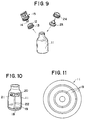
- Japanese Utility Model Application Kokai No. 62-6831 discloses a nursing bottle shown in Figures 10 and 11.
- a signal processor 18 is provided at the bottom of a bottle 11 which is provided, at the bottom, a concentric circular thermoelectric element 19.
- a temperature indicator 20 and a buzzer 21 are provided at the upper part of the bottle 11, which are connected to the signal processor 18 with a wiring 22.
- a digital indication of the temperature is much favorable by being able to indicate the temperature every moment. Generally, however, it is difficult to detect the accurate temperature if a digital liquid crystal thermometer is equipped intimately on the outer surface of the bottle due to the low thermoconductivity of the bottle made of glass or plastic materials. Further, the indicated temperature and the actual inner temperature may generally be different due to radiation of heat by air on the outer surface of the bottle.
- the inner liquid must touch the thin film 12 either by making the bottle 11 upside down or by swinging the bottle in order to detect the accurate temperature, as shown in Figure 8. Even so, a difference of temperature may result if the bottle 11 is allowed to stand for a while after touching of the thin film 12 to the liquid.
- the nursing bottle by this proposition necessitates inconvenience that, as shown in Figure 9, the sealing cap 13 attached to the opening of the bottle 11 and the holding cap 17 equipped with the thermosensor 14 must be taken off, after detection of temperature, and that a nipple 23 and and a nipple cap 24 must be fitted to the opening of the bottle 11. Still further, the temporary storage of the sealing cap 13, the nipple 23 and the nipple cap 24 causes another problem of sanitation.
- the nursing bottle requires sterilization by boiling and this is also true with the nipple and the nipple cap that contact the baby.
- the proposal made by the Japaense Utility Model Application Kokai No. 62-6831 would cause difficulty in sterilizing it by boiling, since the temperature indicator 20, the buzzer 21, the signal processor 18 and the wiring 22 are united with the bottle 11.
- the present invention is, therefore, to provide nursing bottles that can detect temperature of the liquid accurately and that causes no problem in sterilizing by boiling, thus overcoming the drawbacks involved in the prior art nursing bottles.
- the accurate temperature may be indicated, e.g. by sound or light.
- FR-A-2291683 discloses a device for sensing the temperature of a bottles wherein a temperature indicator is a liquid crystal temperature indicator.
- DE-U-8108586 discloses a nursing bottle assembly which comprises a bottle, an upper opening of which is equipped with a detachable nipple, a cap and a detachable case fitted to the bottom of the bottle, and according to the present invention, such an assembly is characterised by means built into the case for giving an alarm in dependence on a proper temperature of a liquid inside the bottle.
- the alarm can be set to go off at a desired temperature, normally 36°C plus/minus 2°C (96.8°F plus/minus 3.6°F), therefore a person heating the bottle can be engaged in other jobs such as taking care of the baby.
- the means for giving an alarm comprises a thermosensor for measuring the temperature of the liquid in the bottle, a substrate supporting an electronic circuit that processes signals from the sensor, an alarm driven by the electronic circuit, and an elastic body supporting the alarm.
- the alarm may be a sound source such as a buzzer, electronic chime or an electric music box, and/or a light source such as a light emitting diode.
- the buzzer is particularly useful for the blind.
- the sensor is preferably a thermister temperature element.
- a battery is preferably attached to the bottom of the case detachably so as to supply electricity to the means for giving an alarm.
- the means for giving the alarm is provided on the surface of the case.
- a dent is provided at the bottom of the bottle. This is preferably provided by making the centre of the bottom wall of the bottle thinner than the rest of the body of the bottle. In this case it is useful to provide an elastic body supporting a or the thermosensor and pushing the thermosensor upwards so as to get the thermosensor in close touch with the dent at the bottom of the bottle, when the case is fitted to the bottom of the bottle.
- a closed space may be formed between the bottom of the bottle and the case, when the case is fitted to the bottle. It is difficult to make the inner and outer temperatures meet due to the radiation of heat on the surface of the bottle. However, an accurate detection of the inner temperature may be made possible by the formation of the space which cuts off aeration.
- a means for indicating the temperature of the liquid in the bottle such as a digital liquid crystal thermoindicator. Therefore in addition to the alarm, an indication of temperature of the milk may be given.
- the case provides a stand for the bottle.
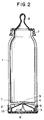
- the bottom of of the body of the nursing bottle 1 (referred to sometimes as the body) is fitted with the case 2.
- the case 2 is fitted to the bottom of the body 1 by engaging the protruding portion, or height, on the part of the case provided inward and the groove on the part of the bottom of the bottle.
- the case 2 may be released from the bottom of the body 1 by detaching the height from the groove.
- the case 2 is composed detachably against the bottom of the body 1 as shown in the Example.
- the case 2 contains a built-in digital liquid crystal appratus T for indicating temperature that comprises a digital liquid crystal temperature indicator 3, a thermosensor 4, an elastic body 5 supporting and pushing upward the said thermosensor, and a substrate 6.
- a cap 7 and a nipple 8 are fitted to the opening of the body 1.
- the botttom of the body 1 is raised and the center of which is made into a dent 9 by making thinner the thickness of that part than the other part of the bottom.
- the top of the thermosensor is supported by the elastic body 5 at the center.
- the top of the thermosensor 4 and the substrate 6 are connected electorically each other with a wiring.
- the thermoelastic body 5 such as rubber or spring
- the substrate 6 and the digital liquid crystal temperature indicating part 3 are also connected electrically.
- Figure 1 shows that the digital liquid crystal temperature indicator 3 indicates the temperature of 38.5°C (101.3°F) of the liquid contained in the body 1.
- a standard temperature suitable for suckling is within the range of 36°C plus/minus 2°C (96.8°F plus/minus 3.6°F), so the temperature indicated in Figure 1 is within a high region (HI).
- the digital liquid crystal temperature indicator 3 When the temperature is detected at the top of the thermosensor 4 closely contacted with the bottom of the body 1, it is indicated digitally on the digital liquid crystal temperature indicating part 3 through the substrate 6. It is possible for the digital liquid crystal temperature indicator 3 not only to indicate the temperature value, such as 38.5°C (101.3°F), but also to indicate words, such as "HI” at a high temperature region and "LO” at a low temperature region. The temperature range may be changed by inputting it previously to the substrate 6.
- the substrate 6 comprises a circuit substrate such as a printed board and is equipped with a control part comprising, e.g. a one chip microcomputer.
- a closed space 10 is formed between the case 2 and the bottom of the body 1, when the case 2 (hereinafter referred to as the "temperature case”) is fitted to the bottom of the body 1.
- a digital liquid crystal temperature apparatus T that indicates the temperature of the liquid contained in the nursing bottle is built in the temperature case 2, which is fitted detachably to the bottom of the body 1.
- the nipple 8 and the cap 7 are fitted to the opening of the body 1.
- the temperature case 2 Since the temperature case 2 is fitted to the bottom of the body 1, it becomes unnecessary to make the body 1 upside down or swing it, and the temperature of the liquid contained in the body 1 may be detected accurately, through the bottom of the body 1, by the temperature indicating appratus T in the temperature case 2. Thus, by fitting the temperature case 2 at the bottom of the body 1, it becomes possible to detect the accurate temperature with a minimum error even if the nursing bottle is allowed to stand, since the liquid stays at the bottom of the body 1.
- the case 2 and the body 1 is detachable each other. So, only the body 1, the nipple 8 and the cap 7 may be sterilized by boiling. This was not feasible in the prior art where the temperature indicator, the signal processor and the wiring are united to the nursing bottle.
- a closed space 10 composed of the case 2 and the bottom of the body 1, when the case 2 is fitted to the bottom of the body 1.
- the heat radiation at the bottom of the body 1 may be minimized and the accurate indication of the inner temperature becomes possible.
- the digital liquid crystal temperature indicating apparatus T comprises the digital liquid crystal temerature indicator 3, the substrate 6 and the thermosensor 4, whereby the proper temperature is notified. Moreover, the apparatus T is equipped with the elastic body 5 which not only support but also push upward the thermosensor 4.
- thermosensor 4 comes into close contact with the bottom of the body 1, by the upward action of the elastic body 5, to create a good thermal sensitive condition.
- thermosensor 4 pushed upward by the action of the elastic body 5 becomes much more closer contact with the bottom of the body 1 by means of the dent 9, whereby a much better thermal sensitivity of the thermosensor 4 may be achieved.
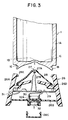
- Figure 3 is the cross sectional view of one of the embodiment of this invention in which the bottle body, the case detachable to the body and the water-proof cap for exchanging battery are shown separately.
- Figure 4 is the cross sectional view of the assembled parts.
- the upper opening of the body 1 is not shown in the Figures.
- the cap 7 and the nipple 8 shown in Figures 1 and 2 are also fitted to the opening of the body 1 in this embodiment, too.
- the inner circumferential part 1B having the smaller diameter than that of the outer circumferential part 1 (that is to say the outer surface of the body) is provided downward.
- the curved, raised bottom 1C is provided upward from the inner circumferential part 1B toward the inside of the body 1.
- the groove 1D which is composed thinner.
- the thermister 27, the elastic body 28, the circuit substrate 29, the sound source 30, the light source 31 and the battery 32 are united in the case 26.
- the thermister 27 is supported by the elastic body 28 at the center, which elastic body 28 being positioned below the thermister 27. Upon contact with the outer side of the body 1, the thermister 27 may be fixed by repulsion to the center of the elastic body 28 and then comes into close contact with the outside of the bottom of the body 1.
- the elastic body 28 is composed, for example, by a rubber or a spring.
- the thermister 27 is connected to the circuit substrate 29 by means of the conductor 27B.
- the circuit substrate 29 is composed, for example, by a resin board. Although not shown, the substrate 29 is provided with a circuit by means of, e.g. printing.
- the circuit substrate 29 is equipped with a one chip microcomputer, a crystal oscillating element, a battery and an output terminal for the external connection.
- the output terminal for the external connection is connected to the light source 31 consisting of, e.g. a light emitting diode or to the sound source consisting of, e.g. a buzzer, an electronic music box or an electronic chime, which is embedded in the side wall of the case 26.
- One example of the operational procedure is: detecting the temperature with the thermosensor thermister 27, actuating the crystal oscillating element to emit the reference frequency (such as response by clock pulse of once a second), switching on the light source 31 or sounding the sound source 30 by means of the terminal function of the output terminal for the external connection via the one chip microcomputer.
- the CPU (central processing unit) of the one chip microcomputer carries out the logical and the comparative operations in accordance with the control program for the proper temperature range stored in the memory element and outputs, being within the proper temperature range, to the light source 31 or the sound source 30 via the output terminal for the external connection.
- Figure 5 is the front view of the nursing bottle when looked from the side of the light source 31.
- thermoelement consists of two different metals (e.g. copper and constantan) and generates the electric force of mV level with the change of the temperature, by utilizing the thermoelectric effect caused by the termperature difference.
- the thermister which may be employed, is composed of the resistance bulb element that is the sintered metal oxide (the metal being, e.g. nickel, manganese or cobalt). With the thermister, the resistance changes, unlike the thermoelements, with inverse proportion as the temperature changes.
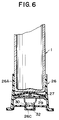
- the cover 26B for placing a battery.
- the sound source 30 such as a buzzer.
- a battery 32 for operating the sound source or the like which battery being connected with the circuit substrate 29 through the terminal 32A, and further with the sound source 30 and the light source 31.
- the battery 32 may be exchanged by releasing the the water-proof cap 26C of the U-shaped cross section.
- the circuit substrate 29 may be supplemented by a circuit constituent so as to discontinue the buzz (e.g. by adoption of a timer circuit), whereby saving the demand of the battery 32.
- the elastic body 28 is provided on the intermediate part 26D of the case 26 in order to support the thermister 27.
- the circuit substrate 29 is provided under the intermediate part 26D, under which a sound source 30 such as a buzzer is provided at the inner face of the case for placing battery 26B.
- a sound source 30 such as a buzzer is provided at the inner face of the case for placing battery 26B.
- a battery On the reverse side of the case 26B there is placed a battery, which is fixed with the detachable water-proof cap 26C.
- the light source 31 such as a light emitting diode so that the emission may be observed from the outside.
- the case 26 and the bottle may be united by engaging the protruding part 26E at the upper part of the case 26A and the groove 1E at the inner circular part 1B of the bottom of the bottle.
- the engagement can be released detachably, whereby sterilization by boiling may be effected easily.
- the water-proof cap 26C and the cover 26B may be united by engaging the protruding part and the groove.
- a closed space 33 may be formed between the bottom of the bottle 1 and the case 26 by fixing the both.
- the space may disturbs the aeration and decreases the radiation of heat at the surface of the bottom, and thus, contributes to an accurate detection of the temperature of the liquid.
- the bottle 1 was provided with a thinner groove 1D at the bottom.
- the frame, or the side wall of the case 26A is extended upward and the mouth of the frame is engaged with the bottom of the bottle 1.
- the thermister 27 pushed upward with the elastic body 28 detects the temperature, when the bottle and the case are engaged, and the sound source 30 and the light source 31 are operated.
- the apparatus is equipped with the sound source 30 and/or the light source 31.
- the digital liquid crystal temperature indicator may be provided, e.g. on the other side of the wall of the case, opposite to the light source. Since this part is connected with the circuit substrate 29, the temperature detected with the thermister 27 may be indicated on the digital liquid crystal temperature indicator, as well as by means of the light source 31 and the sound source 30.
- the positions of the circuit substrate and of the sound source may be changed arbitrarily, as far as they are united in the case.
Landscapes
- Health & Medical Sciences (AREA)
- Life Sciences & Earth Sciences (AREA)
- Animal Behavior & Ethology (AREA)
- General Health & Medical Sciences (AREA)
- Public Health (AREA)
- Veterinary Medicine (AREA)
- Physics & Mathematics (AREA)
- General Physics & Mathematics (AREA)
- Medical Preparation Storing Or Oral Administration Devices (AREA)
- Details Of Rigid Or Semi-Rigid Containers (AREA)
- Measuring Temperature Or Quantity Of Heat (AREA)
- Measuring And Recording Apparatus For Diagnosis (AREA)
- Apparatus For Disinfection Or Sterilisation (AREA)
Claims (13)
- Säuglingsflaschenanordnung mit einer Flasche (1), deren obere Öffnung mit einem abnehmbaren Sauger (8) ausgestattet ist, einem Aufsatz (7) und einem auf dem Boden der Flasche aufgesetzten abnehmbaren Gehäuse (26), gekennzeichnet durch eine in dem Gehäuse eingebaute Einrichtung (30, 31) zum Abgeben eines Alarmsignals in Abhängigkeit von einer geeigneten Temperatur einer Flüssigkeit im Inneren der Flasche.
- Anordnung nach Anspruch 1, bei der die Einrichtung zum Abgeben eines Alarmsignals umfaßt einen Temperaturfühler (27) zum Messen der Temperatur der Flüssigkeit in der Flasche, ein eine Signale von dem Fühler verarbeitende elektronische Schaltung tragendes Substrat (29), eine von der elektronischen Schaltung betriebene Alarmvorrichtung (30, 31) und einen die Alarmvorrichtung tragenden elastischen Körper (28).
- Anordnung nach Anspruch 2, bei der die Alarmvorrichtung eine Geräuschquelle und/oder eine Lichtquelle ist.
- Anordnung nach Anspruch 3, bei der die Geräuschquelle ein Summer, eine elektronische Glocke oder eine elektronische Spieldose ist.
- Anordnung nach Anspruch 3, bei der die Lichtquelle eine lichtaussendende Diode ist.
- Anordnung nach einem der Ansprüche 2 bis 5, bei der der Fühler ein Thermistor-Temperaturelement ist.
- Anordnung nach einem der vorhergehenden Ansprüche, bei der eine Batterie (32) zur Elektrizitätsversorgung der Einrichtung zum Abgeben eines Alarmsignals an dem Boden des Gehäuses abnehmbar angebracht ist.
- Anordnung nach einem der vorhergehenden Ansprüche, bei der die Einrichtung (3, 31) zum Abgeben des Alarms an der Oberfläche des Gehäuses vorgesehen ist.
- Anordnung nach einem der vorhergehenden Ansprüche, bei der eine Einbeulung (9) an dem Boden der Flasche vorgesehen ist.
- Anordnung nach Anspruch 9, bei der die Einbeulung dadurch geliefert ist, daß das Zentrum der Bodenwand der Flasche dünner gebildet ist als der Rest des Flaschenkörpers.
- Anordnung nach Anspruch 10, bei der ein elastischer Körper (28) vorgesehen ist, der einen oder den Temperaturfühler trägt und den Temperaturfühler nach oben drückt, um den Temperaturfühler in enge Berührung mit der Einbeulung an dem Boden der Flasche zu bringen, wenn das Gehäuse auf dem Boden der Flasche aufgesetzt ist.
- Anordnung nach einem der vorhergehenden Ansprüche, bei der vorgesehen ist ein vorspringender Bereich (26E) an dem Gehäuse und eine komplementäre Nut (1E) an dem Boden der Flasche, wodurch ein Schnappeingriff des Gehäuses und der Flasche ermöglicht wird.
- Anordnung nach einem der vorhergehenden Ansprüche, bei der das Gehäuse ein Untergestell für die Flasche liefert.
Applications Claiming Priority (4)
| Application Number | Priority Date | Filing Date | Title |
|---|---|---|---|
| JP52411/88 | 1988-03-05 | ||
| JP5241188A JPH0298359A (ja) | 1988-03-05 | 1988-03-05 | 温度計を装着した哺乳瓶 |
| JP1988160876U JPH0525618Y2 (de) | 1988-12-13 | 1988-12-13 | |
| JP160876/88U | 1988-12-13 |
Related Child Applications (2)
| Application Number | Title | Priority Date | Filing Date |
|---|---|---|---|
| EP19930105582 Division EP0551150A3 (en) | 1988-03-05 | 1989-03-03 | Nursing bottle assembly |
| EP93105582.6 Division-Into | 1993-04-05 |
Publications (3)
| Publication Number | Publication Date |
|---|---|
| EP0332355A2 EP0332355A2 (de) | 1989-09-13 |
| EP0332355A3 EP0332355A3 (de) | 1991-01-30 |
| EP0332355B1 true EP0332355B1 (de) | 1993-11-24 |
Family
ID=26393022
Family Applications (2)
| Application Number | Title | Priority Date | Filing Date |
|---|---|---|---|
| EP19930105582 Withdrawn EP0551150A3 (en) | 1988-03-05 | 1989-03-03 | Nursing bottle assembly |
| EP89302171A Expired - Lifetime EP0332355B1 (de) | 1988-03-05 | 1989-03-03 | Saugflasche |
Family Applications Before (1)
| Application Number | Title | Priority Date | Filing Date |
|---|---|---|---|
| EP19930105582 Withdrawn EP0551150A3 (en) | 1988-03-05 | 1989-03-03 | Nursing bottle assembly |
Country Status (5)
| Country | Link |
|---|---|
| US (2) | US4930902A (de) |
| EP (2) | EP0551150A3 (de) |
| KR (2) | KR900009036A (de) |
| CA (1) | CA1330068C (de) |
| DE (1) | DE68910852T2 (de) |
Cited By (1)
| Publication number | Priority date | Publication date | Assignee | Title |
|---|---|---|---|---|
| US12035843B2 (en) | 2010-11-02 | 2024-07-16 | Ember Technologies, Inc. | Dishware or serverware with active temperature control |
Families Citing this family (68)
| Publication number | Priority date | Publication date | Assignee | Title |
|---|---|---|---|---|
| US5109864A (en) * | 1990-12-21 | 1992-05-05 | Lu Jieh Shan | Nipple assembly with alarm buzzer and body temperature indicator (IV) |
| US5211300A (en) * | 1992-10-01 | 1993-05-18 | Industrial Technology Research Institute | Safety valve for feeding bottle |
| US5447248A (en) * | 1994-01-26 | 1995-09-05 | Rodriguez; Kimberly J. | Indicator for liquid container |
| US5553941A (en) * | 1994-02-18 | 1996-09-10 | Safety-Temp Ltd. | Thermometer and bottle cap assembly |
| US5400610A (en) * | 1994-02-22 | 1995-03-28 | Ero Industries, Inc. | Portable insulated container with temperature indicator |
| USD404491S (en) | 1994-06-01 | 1999-01-19 | Juliet Scott | Baby bottle with temperature indicator |
| US5873892A (en) * | 1994-06-26 | 1999-02-23 | Cohen; Fredie | Thermometric pacifier for infants |
| US5662406A (en) * | 1996-02-06 | 1997-09-02 | Mattice; Johnny M. | Lighted baby bottle |
| US5741069A (en) * | 1996-04-16 | 1998-04-21 | Egel; Kenneth D. | Combined thermometer and radiator cap |
| US5996832A (en) * | 1996-06-26 | 1999-12-07 | Henbase 3172 (Proprietary) Limited | Cover for beverage can |
| US5897207A (en) * | 1997-02-18 | 1999-04-27 | Hartmann; Clay A | Beverage temperature notification device |
| US6467953B1 (en) | 1999-03-30 | 2002-10-22 | Medical Solutions, Inc. | Method and apparatus for monitoring temperature of intravenously delivered fluids and other medical items |
| USD404138S (en) | 1997-07-17 | 1999-01-12 | Gerber Products Company | Combined nipple and collar |
| DE19744526A1 (de) * | 1997-10-09 | 1999-04-15 | Joachim Stuepp | Trinkflasche mit Thermometer |
| US5923257A (en) * | 1998-02-23 | 1999-07-13 | Nolte; Ray J. | Carafe with thermal sensor and digital display |
| US6037872A (en) * | 1998-03-04 | 2000-03-14 | Dunnum; Christopher B. | Baby bottle having removable handles and an automated sound producing means |
| US6020823A (en) * | 1998-07-10 | 2000-02-01 | Decicco; Richard J. | Decorative packaging with special effects |
| USD421306S (en) * | 1998-10-13 | 2000-02-29 | Gerber Products Company | Combined nipple and collar |
| US6225908B1 (en) * | 2000-05-17 | 2001-05-01 | Shu-Finn Lee | Double-layer container equipped with temperature warning device |
| US6353391B1 (en) * | 2000-09-15 | 2002-03-05 | Kenneth N. Shearer | Baby bottle locating system |
| US7238171B2 (en) | 2001-03-12 | 2007-07-03 | Medical Solutions, Inc. | Method and apparatus for controlling pressurized infusion and temperature of infused liquids |
| US6431054B1 (en) * | 2001-03-23 | 2002-08-13 | Benjamin Reid | Hot/cold indicating coffee pot device |
| US6588593B2 (en) * | 2001-04-09 | 2003-07-08 | Steven M. Woskoski | Fluid container with timepiece |
| US6739749B2 (en) * | 2001-12-17 | 2004-05-25 | Ming Tun Hsiao | Thermometric nursing bottle |
| US8226605B2 (en) | 2001-12-17 | 2012-07-24 | Medical Solutions, Inc. | Method and apparatus for heating solutions within intravenous lines to desired temperatures during infusion |
| JP4025218B2 (ja) * | 2003-02-26 | 2007-12-19 | 矢崎総業株式会社 | 温度センサの取付ホルダー |
| US20040247015A1 (en) * | 2003-03-19 | 2004-12-09 | Wojan Scott A. | Beverage and food temperature notification device |
| DE602004010797D1 (en) * | 2003-04-15 | 2008-01-31 | Peter Kinsler | Thermometer |
| US7384164B2 (en) * | 2003-09-16 | 2008-06-10 | Sun Yu | Illuminated liquid dispensing container |
| WO2005036116A2 (en) * | 2003-10-02 | 2005-04-21 | Debra Fogel Harris | Corkscrew with integral intelligent thermometer |
| US20060062085A1 (en) * | 2004-09-22 | 2006-03-23 | Evans Stacy M | Bottle with timing mechanism |
| US20090175315A1 (en) * | 2005-04-26 | 2009-07-09 | John Jeffrey Schwegman | Wireless temperature sensing system for lyophilization processes |
| US7520670B2 (en) * | 2005-04-26 | 2009-04-21 | John Jeffrey Schwegman | Wireless temperature sensing system for lyophilization processes |
| CN2836802Y (zh) * | 2005-08-30 | 2006-11-15 | 王庆广 | 新型电子显温奶瓶 |
| US20080075143A1 (en) * | 2006-09-21 | 2008-03-27 | Vanessa Lampke-Honeyghan | Digital thermometers with audible feedback |
| US7766545B2 (en) * | 2006-10-12 | 2010-08-03 | Deana S. Salkeld | Safety lid and method for use of same |
| US9061795B2 (en) * | 2007-08-20 | 2015-06-23 | Procter & Gamble | Supportable pressurizable container and base cup therefor with alignment tabs |
| US20090184081A1 (en) * | 2008-01-23 | 2009-07-23 | Ming-Jung Wu | Temperature-sensing feeding bottle structure |
| WO2010093755A1 (en) * | 2009-02-10 | 2010-08-19 | Koninklijke Philips Electronics, N.V. | Baby feeding bottle |
| DE102010007434A1 (de) | 2010-02-09 | 2011-08-11 | Mingle Instrument GmbH Europe, 47877 | Thermometer für die Zubereitung von Babynahrung |
| US11950726B2 (en) | 2010-11-02 | 2024-04-09 | Ember Technologies, Inc. | Drinkware container with active temperature control |
| US9814331B2 (en) | 2010-11-02 | 2017-11-14 | Ember Technologies, Inc. | Heated or cooled dishware and drinkware |
| US8717182B1 (en) | 2011-08-02 | 2014-05-06 | Solbrae, Inc. | Mechanism and method to implement a reader mechanism for a container-based monitor of a consumable product |
| US20130092649A1 (en) * | 2011-10-18 | 2013-04-18 | Jie-Feng Yi | Double-Layer Stainless Steel Intelligence Milk Bottle Design |
| US9211381B2 (en) | 2012-01-20 | 2015-12-15 | Medical Solutions, Inc. | Method and apparatus for controlling temperature of medical liquids |
| US9327960B2 (en) | 2014-06-16 | 2016-05-03 | Iqhydr8, Llc | Volume sensing beverage container cap system |
| US9320375B2 (en) * | 2014-06-16 | 2016-04-26 | Iqhydr8, Llc | Activity and volume sensing beverage container cap system |
| US9656029B2 (en) | 2013-02-15 | 2017-05-23 | Medical Solutions, Inc. | Plural medical item warming system and method for warming a plurality of medical items to desired temperatures |
| GB2516006B (en) * | 2013-06-06 | 2016-10-12 | Starspot Ltd | Wine thermometer |
| US20150122765A1 (en) * | 2013-11-07 | 2015-05-07 | Mesha Cannon | Insulated Baby Bottle |
| USD769063S1 (en) | 2014-09-18 | 2016-10-18 | Iqhydr8, Llc | Beverage container cap with handle and integrated hole cover |
| US9782036B2 (en) | 2015-02-24 | 2017-10-10 | Ember Technologies, Inc. | Heated or cooled portable drinkware |
| US20190096224A1 (en) * | 2015-09-10 | 2019-03-28 | Mor ELMODAI | A device for correct feeding posture |
| WO2017192396A1 (en) | 2016-05-02 | 2017-11-09 | Ember Technologies, Inc. | Heated or cooled drinkware |
| WO2017197026A1 (en) | 2016-05-12 | 2017-11-16 | Ember Technologies, Inc. | Drinkware and plateware and active temperature control module for same |
| KR20180035662A (ko) | 2016-09-29 | 2018-04-06 | 엠버 테크놀로지스 인코포레이티드 | 가열되거나 냉각된 음료용기 |
| US10974943B2 (en) * | 2016-11-11 | 2021-04-13 | Fiji Water Company, Llc | Method and apparatus for illuminating the status of a consumable |
| CH713295A2 (de) * | 2016-12-28 | 2018-06-29 | Faitron Ag | Lunchgefäss. |
| CN108245428A (zh) * | 2018-01-30 | 2018-07-06 | 河南沐阳信息技术有限公司 | 一种恒温型智能奶瓶 |
| EP4268687A3 (de) | 2018-01-31 | 2023-12-06 | Ember Technologies, Inc. | Aktiv beheiztes oder gekühltes säuglingsflaschensystem |
| US11298297B2 (en) | 2018-03-27 | 2022-04-12 | Zak Wood | Baby bottle sensor with content volume sensing and content deduction logic |
| US10561582B2 (en) | 2018-03-27 | 2020-02-18 | Zak Wood | Baby bottle sensor with content volume sensing and content deduction logic |
| CN118935853A (zh) | 2018-04-19 | 2024-11-12 | 恩伯技术公司 | 具有主动温度控制的便携式冷却器 |
| EP3906383A2 (de) | 2019-01-11 | 2021-11-10 | Ember Technologies, Inc. | Tragbarer kühler mit aktiver temperaturregelung |
| JP7671256B2 (ja) | 2019-06-25 | 2025-05-01 | イエティ クーラーズ エルエルシー | 携帯型クーラー |
| US11668508B2 (en) | 2019-06-25 | 2023-06-06 | Ember Technologies, Inc. | Portable cooler |
| US11162716B2 (en) | 2019-06-25 | 2021-11-02 | Ember Technologies, Inc. | Portable cooler |
| KR20220163473A (ko) | 2020-04-03 | 2022-12-09 | 엠버 라이프사이언스, 아이엔씨. | 능동적 온도 제어를 가지는 휴대용 쿨러 |
Family Cites Families (34)
| Publication number | Priority date | Publication date | Assignee | Title |
|---|---|---|---|---|
| DE1933C (de) * | L. J. MEYER in Berlin | Säugflasche mit Thermometer | ||
| US197157A (en) * | 1877-11-13 | Improvement in fire-place grates | ||
| CH112492A (de) * | 1925-02-14 | 1925-11-02 | Friedrich Auer | Flaschen, insbesondere Kindersaugflaschen, Laboratoriumsflaschen und dergleichen. |
| US2357692A (en) * | 1943-12-06 | 1944-09-05 | Thomas F Saffady | Flexible thermometer support |
| US2547337A (en) * | 1948-11-04 | 1951-04-03 | Harold E Mckeen | Hot-water bottle stopper or cork |
| US2887239A (en) * | 1958-03-21 | 1959-05-19 | John A Reed | Nursing bottle |
| FR1358496A (fr) * | 1963-03-04 | 1964-04-17 | Biberon avec thermomètre incorporé | |
| US3326358A (en) * | 1965-03-05 | 1967-06-20 | Murine Company Inc | Contact lens case |
| US3546942A (en) * | 1968-08-06 | 1970-12-15 | Walter Thiele | Device for indicating the temperature of a baby bottle |
| DE2048291A1 (de) * | 1970-10-01 | 1972-04-06 | Aider, Emanuel, 6360 Friedberg | Kinderbecher mit Temperaturanzeige |
| US3864976A (en) * | 1973-10-31 | 1975-02-11 | Parker Research Robert | Reusable bottle thermometer |
| IT7422389U1 (it) * | 1974-11-18 | 1976-05-18 | Artsana Spa | Bottiglia per poppanti con elemento luminoso d'indicazione della temperatura |
| DE2828328A1 (de) * | 1978-06-28 | 1980-01-10 | Karl Klama | Nuckelflasche mit temperaturanzeige |
| JPS5519609U (de) | 1978-07-21 | 1980-02-07 | ||
| JPS5545387U (de) | 1978-09-21 | 1980-03-25 | ||
| US4241839A (en) * | 1979-08-14 | 1980-12-30 | Sewell Plastics, Inc. | Base-cup for assuring vertical alignment of semi-hemispherically bottomed bottles |
| JPS56116044U (de) | 1980-02-07 | 1981-09-05 | ||
| JPS575235U (de) | 1980-06-09 | 1982-01-12 | ||
| JPS57113142U (de) | 1981-01-05 | 1982-07-13 | ||
| DE8108586U1 (de) * | 1981-03-24 | 1981-11-19 | Mayer, Helmut, Dipl.-Ing., 6141 Einhausen | Vorrichtung zur temperaturmessung und waermeisolierung von saeuglingsnahrung in saeuglingsflaschen |
| JPS5969738U (ja) | 1982-10-30 | 1984-05-11 | 萩原 みどり | 飲料用瓶 |
| JPS60106634U (ja) | 1983-12-26 | 1985-07-20 | 真坂 嘉直 | 示温塗料をはつたほ乳ビン |
| JPS60184544U (ja) | 1984-05-18 | 1985-12-07 | 中島 梅雄 | 温度計付哺乳びん |
| JPS621627U (de) | 1984-12-15 | 1987-01-08 | ||
| JPS61171974U (de) | 1985-04-12 | 1986-10-25 | ||
| JPS61173038U (de) | 1985-04-17 | 1986-10-28 | ||
| JPS626831U (de) | 1985-06-27 | 1987-01-16 | ||
| US4718776A (en) * | 1985-08-12 | 1988-01-12 | Ball Corporation | Portable monitoring device and method |
| JPS62117537U (de) | 1986-01-17 | 1987-07-25 | ||
| JPS62148235U (de) | 1986-03-13 | 1987-09-19 | ||
| JPS6338529U (de) | 1986-08-27 | 1988-03-12 | ||
| DE3700105A1 (de) * | 1987-01-03 | 1988-07-14 | Lenz Andrea Alexandra | Trinkflasche fuer saeuglinge kombinierbar zum absaugen von muttermilch |
| US4801922A (en) * | 1987-05-14 | 1989-01-31 | Worrell Darhl R | Low temperature alarm |
| US4730744A (en) * | 1987-06-17 | 1988-03-15 | Vinciguerra Mark T | Baby bottle with valve |
-
1989
- 1989-02-28 CA CA000592301A patent/CA1330068C/en not_active Expired - Fee Related
- 1989-03-03 EP EP19930105582 patent/EP0551150A3/en not_active Withdrawn
- 1989-03-03 DE DE89302171T patent/DE68910852T2/de not_active Expired - Fee Related
- 1989-03-03 EP EP89302171A patent/EP0332355B1/de not_active Expired - Lifetime
- 1989-03-03 US US07/319,153 patent/US4930902A/en not_active Expired - Fee Related
- 1989-12-13 KR KR1019890018476A patent/KR900009036A/ko not_active Withdrawn
-
1990
- 1990-03-16 US US07/495,355 patent/US5000581A/en not_active Expired - Fee Related
-
1993
- 1993-09-13 KR KR93018452U patent/KR940005432Y1/ko not_active Expired - Fee Related
Cited By (1)
| Publication number | Priority date | Publication date | Assignee | Title |
|---|---|---|---|---|
| US12035843B2 (en) | 2010-11-02 | 2024-07-16 | Ember Technologies, Inc. | Dishware or serverware with active temperature control |
Also Published As
| Publication number | Publication date |
|---|---|
| KR900009036A (ko) | 1990-07-02 |
| KR940005432Y1 (en) | 1994-08-11 |
| EP0332355A2 (de) | 1989-09-13 |
| DE68910852T2 (de) | 1994-03-17 |
| DE68910852D1 (de) | 1994-01-05 |
| EP0551150A3 (en) | 1993-08-11 |
| EP0332355A3 (de) | 1991-01-30 |
| US4930902A (en) | 1990-06-05 |
| EP0551150A2 (de) | 1993-07-14 |
| US5000581A (en) | 1991-03-19 |
| CA1330068C (en) | 1994-06-07 |
Similar Documents
| Publication | Publication Date | Title |
|---|---|---|
| US4930902A (en) | Nursing bottles | |
| US6794990B2 (en) | Electronic patch thermometer | |
| US6976783B2 (en) | Assembly method and structure of an electronic clinical thermometer | |
| US7354195B2 (en) | Temperature measuring device and temperature measuring method | |
| US7417417B2 (en) | Spill-resistant beverage container with detection and notification indicator | |
| US8752719B2 (en) | Baby feeding bottle | |
| EP1909087A2 (de) | Diebstahlsicherungssystem für ein Thermometer | |
| JP3161231U (ja) | おしゃぶり体温計 | |
| GB2148010A (en) | Electronic clinical thermometer | |
| US20110043368A1 (en) | Thermometer | |
| GB2286684A (en) | Skin temperature sensing device | |
| JPH0525618Y2 (de) | ||
| CN201275278Y (zh) | 一种显温测湿奶瓶 | |
| EP1643228B1 (de) | Ein elektronisches klinisches thermometer mit einer abnehmbaren Sonde | |
| CA1334188C (en) | Nursing bottles | |
| WO1990010854A1 (en) | Thermometer | |
| GB2163855A (en) | Clinical thermometer in form of a dummy teat | |
| CN215374292U (zh) | 一种自动提醒测温及快速测量体温装置 | |
| CN113155319A (zh) | 一种自动提醒测温及快速测量体温装置及方法 | |
| CN206960003U (zh) | 侧贴式奶瓶温度检测器 | |
| JPH0724102Y2 (ja) | 液温表示機能付哺乳瓶 | |
| CN201032466Y (zh) | 测温器 | |
| WO1995005774A1 (en) | Measuring system and measuring sensor for measuring a quantity of urine | |
| JP2507967Y2 (ja) | 体温表示付きおしゃぶり | |
| JPH0650347B2 (ja) | 圧力センサ付電子機器 |
Legal Events
| Date | Code | Title | Description |
|---|---|---|---|
| PUAI | Public reference made under article 153(3) epc to a published international application that has entered the european phase |
Free format text: ORIGINAL CODE: 0009012 |
|
| 17P | Request for examination filed |
Effective date: 19890330 |
|
| AK | Designated contracting states |
Kind code of ref document: A2 Designated state(s): DE FR GB IT |
|
| PUAL | Search report despatched |
Free format text: ORIGINAL CODE: 0009013 |
|
| AK | Designated contracting states |
Kind code of ref document: A3 Designated state(s): DE FR GB IT |
|
| 17Q | First examination report despatched |
Effective date: 19920914 |
|
| GRAA | (expected) grant |
Free format text: ORIGINAL CODE: 0009210 |
|
| AK | Designated contracting states |
Kind code of ref document: B1 Designated state(s): DE FR GB IT |
|
| XX | Miscellaneous (additional remarks) |
Free format text: TEILANMELDUNG 93105582.6 EINGEREICHT AM 03/03/89. |
|
| ITF | It: translation for a ep patent filed | ||
| ET | Fr: translation filed | ||
| REF | Corresponds to: |
Ref document number: 68910852 Country of ref document: DE Date of ref document: 19940105 |
|
| PGFP | Annual fee paid to national office [announced via postgrant information from national office to epo] |
Ref country code: GB Payment date: 19940902 Year of fee payment: 6 |
|
| PLBE | No opposition filed within time limit |
Free format text: ORIGINAL CODE: 0009261 |
|
| STAA | Information on the status of an ep patent application or granted ep patent |
Free format text: STATUS: NO OPPOSITION FILED WITHIN TIME LIMIT |
|
| PGFP | Annual fee paid to national office [announced via postgrant information from national office to epo] |
Ref country code: DE Payment date: 19940930 Year of fee payment: 6 |
|
| 26N | No opposition filed | ||
| PG25 | Lapsed in a contracting state [announced via postgrant information from national office to epo] |
Ref country code: FR Effective date: 19941130 |
|
| REG | Reference to a national code |
Ref country code: FR Ref legal event code: ST |
|
| PG25 | Lapsed in a contracting state [announced via postgrant information from national office to epo] |
Ref country code: GB Effective date: 19950303 |
|
| GBPC | Gb: european patent ceased through non-payment of renewal fee |
Effective date: 19950303 |
|
| PG25 | Lapsed in a contracting state [announced via postgrant information from national office to epo] |
Ref country code: DE Effective date: 19951201 |
|
| PG25 | Lapsed in a contracting state [announced via postgrant information from national office to epo] |
Ref country code: IT Free format text: LAPSE BECAUSE OF NON-PAYMENT OF DUE FEES Effective date: 20050303 |