EP0332412A1 - Dispositif de contrôle simultané des franges d'interférences et de la puissance pour un gyroscope à laser en anneau - Google Patents
Dispositif de contrôle simultané des franges d'interférences et de la puissance pour un gyroscope à laser en anneau Download PDFInfo
- Publication number
- EP0332412A1 EP0332412A1 EP89302289A EP89302289A EP0332412A1 EP 0332412 A1 EP0332412 A1 EP 0332412A1 EP 89302289 A EP89302289 A EP 89302289A EP 89302289 A EP89302289 A EP 89302289A EP 0332412 A1 EP0332412 A1 EP 0332412A1
- Authority
- EP
- European Patent Office
- Prior art keywords
- axis
- gyroscope
- segment
- photocurrent
- fringe pattern
- Prior art date
- Legal status (The legal status is an assumption and is not a legal conclusion. Google has not performed a legal analysis and makes no representation as to the accuracy of the status listed.)
- Withdrawn
Links
- 238000012544 monitoring process Methods 0.000 title description 13
- 238000001514 detection method Methods 0.000 description 10
- 238000012545 processing Methods 0.000 description 6
- 230000008901 benefit Effects 0.000 description 5
- 238000000034 method Methods 0.000 description 5
- 238000000576 coating method Methods 0.000 description 4
- 238000010586 diagram Methods 0.000 description 4
- 239000011248 coating agent Substances 0.000 description 3
- 238000005259 measurement Methods 0.000 description 3
- 230000003287 optical effect Effects 0.000 description 3
- 230000008569 process Effects 0.000 description 3
- 230000004044 response Effects 0.000 description 3
- 239000000758 substrate Substances 0.000 description 3
- 230000000712 assembly Effects 0.000 description 2
- 238000000429 assembly Methods 0.000 description 2
- 230000009977 dual effect Effects 0.000 description 2
- 239000000463 material Substances 0.000 description 2
- 241000282320 Panthera leo Species 0.000 description 1
- 239000006094 Zerodur Substances 0.000 description 1
- 239000000654 additive Substances 0.000 description 1
- 230000000996 additive effect Effects 0.000 description 1
- 238000013459 approach Methods 0.000 description 1
- 230000001276 controlling effect Effects 0.000 description 1
- 238000013461 design Methods 0.000 description 1
- 230000000694 effects Effects 0.000 description 1
- 230000008030 elimination Effects 0.000 description 1
- 238000003379 elimination reaction Methods 0.000 description 1
- 238000005516 engineering process Methods 0.000 description 1
- 230000004907 flux Effects 0.000 description 1
- 238000005286 illumination Methods 0.000 description 1
- 230000008676 import Effects 0.000 description 1
- 238000012986 modification Methods 0.000 description 1
- 230000004048 modification Effects 0.000 description 1
- 230000000737 periodic effect Effects 0.000 description 1
- 230000001105 regulatory effect Effects 0.000 description 1
- 230000000717 retained effect Effects 0.000 description 1
- 230000035945 sensitivity Effects 0.000 description 1
- 238000000926 separation method Methods 0.000 description 1
- 230000002123 temporal effect Effects 0.000 description 1
Images


Classifications
-
- G—PHYSICS
- G01—MEASURING; TESTING
- G01C—MEASURING DISTANCES, LEVELS OR BEARINGS; SURVEYING; NAVIGATION; GYROSCOPIC INSTRUMENTS; PHOTOGRAMMETRY OR VIDEOGRAMMETRY
- G01C19/00—Gyroscopes; Turn-sensitive devices using vibrating masses; Turn-sensitive devices without moving masses; Measuring angular rate using gyroscopic effects
- G01C19/58—Turn-sensitive devices without moving masses
- G01C19/64—Gyrometers using the Sagnac effect, i.e. rotation-induced shifts between counter-rotating electromagnetic beams
- G01C19/66—Ring laser gyrometers
- G01C19/661—Ring laser gyrometers details
- G01C19/662—Ring laser gyrometers details signal readout; dither compensators
Definitions
- the present invention relates to gyroscopes and more particularly to an assembly for detecting the fringe pattern and monitoring the power of laser beams circulating within a cavity of a ring laser gyroscope.
- a conventional ring laser gyroscope uses a beam combiner optics assembly to fulfill two functions: that is, to detect the rotation of the gyroscope, with respect to inertial space, and to monitor the power level of the laser beams circulating within a cavity of the gyroscope.
- two or three photodetectors had to be used; while for a three-axis gyroscope, a total of six or nine photodetectors, two or three photodetectors for each of the axes, have been needed.
- the power level signal carries a time-varying (ac) gyro rotation signal, the so-called "winking" signal, which needs to be eliminated.
- the present invention assembly instead of using two or three different photodetectors for each axis of a three-axis ring laser gyroscope, would only use, for each of the axes, one photodiode that is divided into four segments. By combining the outputs from these segments and by means of appropriate electronic circuitry, both fringe pattern detection and the monitoring of the power level of the laser beams are achieved.
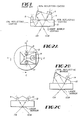
- Fig. 1 shows, in cross-sectional view, a beam combiner assembly for a single axis ring laser gyroscope, hereinafter referred to as RLG.
- the Fig. 1 assembly includes a light transmissive block 2, preferably made out of a low coefficient of expansion material such as Zerodur (or other similar material), on top of which is mounted a prism 4.
- the purpose of this beam combiner optics assembly is to detect the rotation of the gyroscope (or gyro) and to monitor the power of the counter-rotating (or counter-propagating)laser beams, such as CW and CCW, circulating within the cavity about the axis of the gyroscope.
- the prior art assembly would use two photodetectors, i.e. photodiodes 6 and 8, as shown, mounted on a facet of prism 4 and the top surface of block 2, respectively.
- the circulating beams would refract through the laser mirror coating and be reflected, per shown arrow lines, to photodiode 6 where the rotation of the gyroscope is determined by the apparent motion of fringes across the face of the photodiode.
- One of the beams in this instance the CCW beam, is also reflected, by the 10% reflecting coating, to photodiode 8 where the power of the laser beam, and thus the power within the laser cavity, is measured and fed back to a circuit for controlling the pathlength of the laser beams.
- two photodiodes 9 and 10 are used to monitor the power of the circulating laser beams. As shown, these photodiodes are mounted on a beam combiner prism 12 which further has an additional photodiode 14 mounted on a different facet thereof. As taught in the aforenoted '377 copending application, photodiode 14 is used to detect the fringe pattern, i.e., the rotation of the gyro.
- each of the beam combiner assemblies is mounted on a mirror that intercepts two axes of the gyroscope.
- the mirror such as the laser mirror shown in Figs. 2B and 2C, is shared by two axes of the gyroscope and would in effect have four laser beams impinging thereon.
- two of the beams that strike the laser mirror are from a first axis while the other two beams striking the same laser mirror would be from an axis orthogonal to the first axis.
- all three axes of a three-axis RLG both in terms of the respective power levels and rotations, are covered.
- the beam combiner prism For the measurement of the gyro rotation rate, the beam combiner prism, such as those of Figs. 1 and 2A to 2C, would combine the two counter-rotating laser beams to form an interference pattern (or a fringe pattern) at the surface of photodiode 6 or 14.
- This fringe pattern moves across the face of the photodiode in a direction transverse to the fringe direction at a rate that is proportional to the rotation rate of the gyroscope.
- a photodiode 15 contains two fringe segments, F1 and F2, which are oriented in parallel to the direction of the fringes, illustrated by the sinusoidal curve on top of the fringe segments.
- the fringe spacing is adjusted so as to be four times the center-to-center distance of the photodiode segments.
- the moving fringes When the gyro rotates about the sensing axis, the moving fringes generate an alternating electrical signal in each of the photodiode segments.
- These signals then are amplified, by photocurrent amplifiers 17, and sent to logic components such as voltage comparators 19 and flip-flop 21 to produce a pair of logic signal outputs A and Q, respectively indicating the rate at which the fringe pattern moves across the photodiode, thereby indicating the rotation rate of the gyro, and the direction in which the fringe pattern is moving, thereby indicating the rotational direction of the gyro.
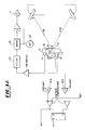
- a prior art fringe detector and pathlength control circuit for a single-axis gyro.
- the output of photodiode 8 is used.
- a closed optical cavity ABC there is circulating in opposite directions traveling waves CW and CCW, shown confined by reflective mirrors B and C and partially transmissive mirror A at the apexes of the triangle ABC.
- two of the mirrors, at B and C are movable in response to voltage output of a summing amplifier 11 so as to maintain the cavity tuned to form an oscillator at the optical lasing frequency.
- Mirror 13 at A being a partially transmissive mirror, allows processing of light from beams CW and CCW, by combiner prism 4 and light transmissive substrate 2, to produce a fringe pattern on dual segment photodiode 6.
- Photocurrents produced in photodiode 6 are amplified by dual fringe detector preamplifiers 50a and 50b, the outputs of which are processed to produce incremental angular output pulses in response to the sensor rotation, as previously described.
- light from beam CCW is internally partially reflected at two surfaces 16 and 18 of light transmissive substrate 2 and transmitted to photodiode 8, the photocurrent of which is amplified by a preamplifier 20 and further processed to serve as a measure of cavity tuning.
- a preamplifier 20 produces a sinusoidal voltage, applied to amplifier 11, which in turn vibrates the mirrors at apexes B and C.
- the sinusoidal voltage is also applied to a demodulator 24 as a phase reference in the phase-sensitive demodulation of the signal at the output of preamplifier 20.
- Filter 26, in some implementations of pathlength control loops (PLC), is often not used.
- Fig. 4B Focusing on Fig. 4B, there is illustrated maximum laser intensity (for a tuned cavity), at point a on the intensity-versus-pathlength curve.
- a small sinusoidal modulation b of the pathlength produces no corresponding intensity modulation at that frequency due to the flatness of the curve at point a.
- the known approach recognizes that the same modulation c at point d on the curve produces an output e bearing the same phase as c, due to the positive slope of the curve at point d. Were the modulation at point f, the output phase would be reversed (not shown).
- the magnitude and phase of the intensity modulation are used by the pathlength control loop as error indications to cause automatic repositioning of the movable mirrors at apexes B and C (Fig. 4A) to achieve optimum operation at point a of the Fig. 4B intensity curve.
- time-varying gyro rotation signals tend to cancel when using CW and CCW power detecting photodiodes, since those signals are out of phase. This is important insofar as the presence of an outside signal near the operating frequency of the power regulating circuit will disrupt its operation.
- Fig. 5 illustrates a first preferred embodiment of the present invention.
- a four segment photodiode 28 having segments F1 to F4, with respective outputs connected to photocurrent amplifiers PA1 to PA4, is shown. Similar to the two segment photodiode shown in Fig. 3, photodiode 28 is oriented parallel to the direction of the fringes and in the same manner as that shown in Fig. 2B. See also assembly 34 in Fig. 6. It should be noted, however, that the power detection portion that requires photodiodes 9 and 10 in Figs. 2A and 2C, is missing in assembly 34. Instead, power detection is accomplished in the instant invention by processing the outputs of the four segment photodiode through a summing amplifier 30, as shown in Fig. 5.
- the fringe pattern spacing relative to the photodiode segment spacing remains the same, per Fig. 3; that is, there remains a 90° spatial separation of the adjacent segments.
- the difference in phase between segments F1 and F2, between segments F2 and F3, between segments F3 and F4, and between segments F4 and F1 could be processed in the same manner as that discussed with respect to Fig. 3, in order to obtain the rate of rotation and the direction of the fringe motion.
- a preferred method would be to process the difference between alternate segment pairs, i.e., between the outputs of segments F1 and F3 and between the outputs of segments F2 and F4, thereby obtaining the benefit of processing the signals, produced by 100% of the incident light impinging on the four segment photodiode.
- the four segment photodiode illustratively, is of the type manufactured by United Detector Technology of Culver City, California 90230. It should be noted that a photodiode having more than four segments may also be used. Yet it has been found that a greater than four segment photodiode adds nothing substantive, except expense and redundancy, to the invention. Likewise, a three segment photodiode has been envisioned; but the use of such photodiode would entail complicated scaling manipulations.
- Amplifiers DA1 and DA2 measure the difference between the output signals from the respective photocurrent amplifier pairs and provide a difference signal to comparators VC1 and VC2, which operate as analog to voltage converters for transmitting logic signals to flip-flop 32.
- the outputs from this portion of the Fig. 5 circuit results in the detection of the magnitude, outputted at A, and the direction, outputted at Q, of the fringe pattern.
- All of the just discussed amplifiers, comparators and flip-flop are conventional electronic components and are made by a number of companies, including for example Intel and Texas Instruments.
- the highest sensitivity signal is obtained.
- an improved signal-to-noise ratio is accomplished since the signal components are added algebraically while the noise contributions are combined statistically.
- the segments whose output differences are processed into fringe signals which, because they are 180° out of phase and are subtracted, produce additive harmonic outputs.
- the outputs of difference amplifiers DA1 and DA2 since their signals differ in phase by 90° and they have zero dc (or average) components by virtue of the subtraction process, when fed to the respective voltage comparators VC1 and VC2, would produce rate and direction information per as discussed.
- the second portion of the Fig. 5 circuitry deals with the power monitoring aspect of the instant invention.
- the respective outputs from photocurrent amplifiers PA1 to PA4 are fed to a conventional summing amplifier 30 which, in response to the input signals, produces an output level that is free of time varying signals.
- the photocurrent amplifier outputs intercept 360 spatial degrees of the periodic fringe pattern, thereby producing a zero average value for that harmonic component.
- the output level is proportional to the spatially integrated level of illuminations (or incident light flux) of the four photodiode segments F1 to F4, including any temporal modulation of that intensity such as typically used in pathlength control means.
- the output from summing amplifier 30 is transmitted to a pathlength control loop (PLC), which is more clearly shown in Fig. 6.
- PLC pathlength control loop
- FIG. 6 a block diagram illustrating the complete circuitry for detecting the fringe pattern and measuring the power of the laser beams in a particular cavity along an axis of a RLG is shown.
- the components shown in Fig. 6 which are the same as those shown in Figs. 5 and 4A are labelled the same. Comparing the Fig. 4A circuit with the Fig. 6 circuit, it can be seen that, with reference to the power monitoring portion of the circuit, the Fig. 6 circuit no longer needs to have preamplifier 20 and filter 26.
- the ac component i.e., the time varying component, has been removed by summing amplifier 30.
- fringe pattern detection portion As for the fringe pattern detection portion, it should be noted that different types of amplifiers are used to convert the same outputs, such as those fed to summing amplifier 30, from assembly 34 to measure the fringe pattern. Of particular import is the fact that albeit assembly 34, at first glance, appears to resemble the assembly shown in Fig. 2B, it should be remembered that beam combiner assembly 34 has a four segment photodiode 28 while photodiode 14 (for the Fig. 2B assembly) is only utilizing two segments and is used strictly for fringe pattern detection.
- Fig. 6 embodiment uses only one photodiode instead of at least two for a single axis gyro; utilizing less reflective coatings on the beam combiner prism - for example, the elimination of the 10% reflecting coating shown in Fig. 1; obtaining an inherently higher signal level for both the rotation sensing and the power sensing functions, since all of the incident light from both circulating laser beams is used for both functions; and eliminating the time varying gyro rotation signal, also known as the winking signal, from the power level signal.
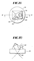
- a second embodiment illustrated in Figs. 7A and 7B, illustrates the use of two photodiodes for performing both functions for two axes of a three-axis RLG.
- a beam combiner prism 34 mounted on a light transmissive substrate 36 has fixedly coupled to facets 38 and 40 photodiodes 42 and 44, respectively.
Landscapes
- Physics & Mathematics (AREA)
- Engineering & Computer Science (AREA)
- Optics & Photonics (AREA)
- Electromagnetism (AREA)
- Power Engineering (AREA)
- General Physics & Mathematics (AREA)
- Radar, Positioning & Navigation (AREA)
- Remote Sensing (AREA)
- Gyroscopes (AREA)
- Lasers (AREA)
Applications Claiming Priority (2)
| Application Number | Priority Date | Filing Date | Title |
|---|---|---|---|
| US16767588A | 1988-03-07 | 1988-03-07 | |
| US167675 | 1988-03-07 |
Publications (1)
| Publication Number | Publication Date |
|---|---|
| EP0332412A1 true EP0332412A1 (fr) | 1989-09-13 |
Family
ID=22608325
Family Applications (1)
| Application Number | Title | Priority Date | Filing Date |
|---|---|---|---|
| EP89302289A Withdrawn EP0332412A1 (fr) | 1988-03-07 | 1989-03-07 | Dispositif de contrôle simultané des franges d'interférences et de la puissance pour un gyroscope à laser en anneau |
Country Status (2)
| Country | Link |
|---|---|
| EP (1) | EP0332412A1 (fr) |
| JP (1) | JPH0214588A (fr) |
Cited By (5)
| Publication number | Priority date | Publication date | Assignee | Title |
|---|---|---|---|---|
| WO1990012286A1 (fr) * | 1989-04-03 | 1990-10-18 | Teldix Gmbh | Laser gyroscopique |
| DE3939904A1 (de) * | 1989-12-02 | 1991-06-06 | Teldix Gmbh | Ringlaserkreisel |
| EP0577030A1 (fr) * | 1992-06-29 | 1994-01-05 | Honeywell Inc. | Système de traitement de signaux à lectures multiples pour gyroscope à laser en anneau |
| DE102012015209B3 (de) * | 2012-08-03 | 2013-11-28 | Technische Universität Braunschweig Carolo-Wilhelmina | Ringlaserkreisel |
| EP2706324A3 (fr) * | 2012-09-11 | 2015-07-15 | Japan Aviation Electronics Industry Limited | Gyrolaser annulaire |
Families Citing this family (2)
| Publication number | Priority date | Publication date | Assignee | Title |
|---|---|---|---|---|
| JP5027584B2 (ja) * | 2007-07-27 | 2012-09-19 | ミネベア株式会社 | 半導体リングレーザジャイロ |
| JP4847509B2 (ja) * | 2008-11-26 | 2011-12-28 | 日本航空電子工業株式会社 | リングレーザジャイロ |
Citations (5)
| Publication number | Priority date | Publication date | Assignee | Title |
|---|---|---|---|---|
| US4219276A (en) * | 1978-10-02 | 1980-08-26 | Rockwell International Corporation | Detection system for ring laser gyro |
| US4320974A (en) * | 1980-06-30 | 1982-03-23 | The Singer Company | Pathlength controller for a ring laser cyroscope |
| FR2532418A1 (fr) * | 1982-08-26 | 1984-03-02 | British Aerospace | Gyroscopes a laser en anneau |
| GB2137013A (en) * | 1983-03-17 | 1984-09-26 | Singer Co | Pathlength controller for three-axis ring laser gyroscope assembly |
| US4637723A (en) * | 1982-09-30 | 1987-01-20 | Honeywell Inc. | Discriminant apparatus for ring laser angular rate sensors |
-
1989
- 1989-03-07 EP EP89302289A patent/EP0332412A1/fr not_active Withdrawn
- 1989-03-07 JP JP5486589A patent/JPH0214588A/ja active Pending
Patent Citations (5)
| Publication number | Priority date | Publication date | Assignee | Title |
|---|---|---|---|---|
| US4219276A (en) * | 1978-10-02 | 1980-08-26 | Rockwell International Corporation | Detection system for ring laser gyro |
| US4320974A (en) * | 1980-06-30 | 1982-03-23 | The Singer Company | Pathlength controller for a ring laser cyroscope |
| FR2532418A1 (fr) * | 1982-08-26 | 1984-03-02 | British Aerospace | Gyroscopes a laser en anneau |
| US4637723A (en) * | 1982-09-30 | 1987-01-20 | Honeywell Inc. | Discriminant apparatus for ring laser angular rate sensors |
| GB2137013A (en) * | 1983-03-17 | 1984-09-26 | Singer Co | Pathlength controller for three-axis ring laser gyroscope assembly |
Cited By (5)
| Publication number | Priority date | Publication date | Assignee | Title |
|---|---|---|---|---|
| WO1990012286A1 (fr) * | 1989-04-03 | 1990-10-18 | Teldix Gmbh | Laser gyroscopique |
| DE3939904A1 (de) * | 1989-12-02 | 1991-06-06 | Teldix Gmbh | Ringlaserkreisel |
| EP0577030A1 (fr) * | 1992-06-29 | 1994-01-05 | Honeywell Inc. | Système de traitement de signaux à lectures multiples pour gyroscope à laser en anneau |
| DE102012015209B3 (de) * | 2012-08-03 | 2013-11-28 | Technische Universität Braunschweig Carolo-Wilhelmina | Ringlaserkreisel |
| EP2706324A3 (fr) * | 2012-09-11 | 2015-07-15 | Japan Aviation Electronics Industry Limited | Gyrolaser annulaire |
Also Published As
| Publication number | Publication date |
|---|---|
| JPH0214588A (ja) | 1990-01-18 |
Similar Documents
| Publication | Publication Date | Title |
|---|---|---|
| US5151585A (en) | Coherent radiation detector | |
| US3419330A (en) | Diffraction grating angular rate sensor | |
| CA1192648A (fr) | Appareil discriminant pour gyroscopes a laser | |
| US4606637A (en) | Dithered ring laser gyroscope with residual lock-in error compensation | |
| EP0332412A1 (fr) | Dispositif de contrôle simultané des franges d'interférences et de la puissance pour un gyroscope à laser en anneau | |
| CA1192975A (fr) | Systeme de polarisation eliminant les erreurs | |
| JPS63194380A (ja) | リングレーザジャイロスコープの回転速度を決定するための信号を生成するためのシステムおよび方法 | |
| US4514832A (en) | Single mirror ring laser gyro readout without combining optics | |
| US4783169A (en) | Control of a ring laser gyro cavity according to a preselected model | |
| US4536087A (en) | Dither compensator for ring laser gyroscope | |
| US5044749A (en) | Fiber-optic bender beam interferometer rate sensor | |
| US5450197A (en) | Device and method for reducing angular random walk in a ring laser gyroscope | |
| Kersey et al. | Open loop fibre optic gyroscope with phase shift nulling signal processing | |
| US4064435A (en) | Radial optical encoder apparatus for shaft angle measurement | |
| US3545866A (en) | Ring laser which utilizes only one of the counterrotating beams to determine rotation rate | |
| US4781462A (en) | Path length control signal derivation circuit for a laser angular rate sensor | |
| US4871253A (en) | Readout apparatus for a laser angular rate sensor | |
| Silvertooth | Motion through the ether | |
| US6446217B1 (en) | System for determining and controlling the peak amplitude and phase of an oscillating member | |
| JPH0587590A (ja) | エンコーダ | |
| SU1215004A1 (ru) | Устройство дл измерени перемещений | |
| US4791460A (en) | Readout for a ring laser angular rate sensor | |
| JPH0324794B2 (fr) | ||
| US5074660A (en) | Method and apparatus for measuring rotating movements | |
| GB2301932A (en) | Correcting ring laser gyroscope phase angle errors induced by lock-in |
Legal Events
| Date | Code | Title | Description |
|---|---|---|---|
| PUAI | Public reference made under article 153(3) epc to a published international application that has entered the european phase |
Free format text: ORIGINAL CODE: 0009012 |
|
| AK | Designated contracting states |
Kind code of ref document: A1 Designated state(s): BE CH DE FR GB IT LI NL SE |
|
| STAA | Information on the status of an ep patent application or granted ep patent |
Free format text: STATUS: THE APPLICATION IS DEEMED TO BE WITHDRAWN |
|
| 18D | Application deemed to be withdrawn |
Effective date: 19900314 |