EP0332420A2 - Presse hydraulique - Google Patents
Presse hydraulique Download PDFInfo
- Publication number
- EP0332420A2 EP0332420A2 EP89302303A EP89302303A EP0332420A2 EP 0332420 A2 EP0332420 A2 EP 0332420A2 EP 89302303 A EP89302303 A EP 89302303A EP 89302303 A EP89302303 A EP 89302303A EP 0332420 A2 EP0332420 A2 EP 0332420A2
- Authority
- EP
- European Patent Office
- Prior art keywords
- lever
- shaft
- movement
- rest position
- movable
- Prior art date
- Legal status (The legal status is an assumption and is not a legal conclusion. Google has not performed a legal analysis and makes no representation as to the accuracy of the status listed.)
- Withdrawn
Links
Images


Classifications
-
- B—PERFORMING OPERATIONS; TRANSPORTING
- B30—PRESSES
- B30B—PRESSES IN GENERAL
- B30B1/00—Presses, using a press ram, characterised by the features of the drive therefor, pressure being transmitted directly, or through simple thrust or tension members only, to the press ram or platen
- B30B1/18—Presses, using a press ram, characterised by the features of the drive therefor, pressure being transmitted directly, or through simple thrust or tension members only, to the press ram or platen by screw means
- B30B1/20—Presses, using a press ram, characterised by the features of the drive therefor, pressure being transmitted directly, or through simple thrust or tension members only, to the press ram or platen by screw means driven by hand
-
- B—PERFORMING OPERATIONS; TRANSPORTING
- B30—PRESSES
- B30B—PRESSES IN GENERAL
- B30B1/00—Presses, using a press ram, characterised by the features of the drive therefor, pressure being transmitted directly, or through simple thrust or tension members only, to the press ram or platen
- B30B1/32—Presses, using a press ram, characterised by the features of the drive therefor, pressure being transmitted directly, or through simple thrust or tension members only, to the press ram or platen by plungers under fluid pressure
Definitions
- This invention relates to a manually controllable hydraulic press.
- British patent number 2119682 discloses an hydraulic press which is manually controllable by rotation of a vertically extending shaft of an hydraulic control mechanism of the press.
- the shaft protrudes upwardly through the top of the housing of the press and secured thereto is a horizontally disposed hand wheel for effecting manual rotation of the shaft.
- rotation of the hand wheel results, by virtue of a screw mechanism, in rectilinear movement of the movable tool of the press without any hydraulic assistance.
- immediately resistance to movement of the movable tool of the press is experienced then hydraulic assistance to movement of the movable tool is provided, the extent of the hydraulic assistance being determined by the torque applied to the rotatable shaft by the hand wheel.
- British patent 2119682 is particularly advantageous, but controlled by means of a hand wheel positioned above the top of the press housing is inconvenient, and it is an object of the present invention to provide an hydraulic press of the kind disclosed in British patent 2119682 incorporating a more convenient control mechanism.
- an hydraulic press having a fixed tool carrier, a movable tool carrier, a first rotatable shaft for generating movement of the movable tool carrier towards and away from the fixed tool carrier, said shaft having its axis aligned with the direction of the movement of the movable tool carrier, a second rotatable shaft extending transverse to said first rotatable shaft, drive transmission means coupling said first and second shafts, an angularly movable, manual operating lever, centering means urging said lever to a central, rest position from which said lever is movable manually in opposite angular directions, and, coupling means for coupling said lever to said second shaft during angular movement of the lever in either direction from said central, rest position, said shaft being rotatable relative to said lever in said central, rest position.
- said lever is angularly movable about the axis of said second shaft.
- said coupling means comprises first and second ratchet discs rotatable with said second shaft, respective first and second pawls carried by said lever and cooperable respectively with said first and second ratchet discs said first pawl cooperating with said first ratchet disc during clockwise angular movement of the lever so as to transmit such clockwise movement of the lever to said second shaft, said second pawl cooperating with said second ratchet disc during counter-clockwise movement of the lever so as to transmit such counter-clockwise movement of the lever to said second shaft, and, the coupling means further including pawl lifting means operable in the central rest position of the lever to disengage both of said first and second pawls from their respective ratchet discs.
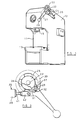
- the hydraulic press includes a C-shaped frame 11 partially enclosed by a sheet metal housing 12.
- the lower horizontal limb of the C-shaped frame 11 carries a rigid bed 13 constituting a fixed tool support, and the upper horizontal limb of the frame 11 carries an hydraulic assisted moving tool mechanism 14 including a moving tool carrier 15.
- the carrier 15 is movable vertically towards and away from the bed 13 in a rectilinear path, the carrier 15 extending from the lower end of the mechanism 14 and there being a rotatable shaft 16 extending from the upper end of the mechanism 14 co-axial with the carrier 15.
- a detailed understanding of the mechanism 14 is not of importance to the present invention, and the mechanism is fully described in British patent 2119682.
- the shaft is rotatable by means of a hand wheel horizontally disposed at the exterior of the housing, and carried at the free end of the shaft.
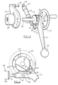
- the free end of the shaft 16 carries a 45° bevel gear 19 the teeth of which mesh with a second 45° bevel gear 21 secured to a second rotatable shaft 22.
- the shaft 22 extends at right angles to the shaft 16, and thus extends horizontally.
- the bevel gear pair constitute a drive transmission whereby rotation of the shaft 22 in either direction is transmitted to the shaft 16 at a 1 : 1 ratio.
- the shaft 22 protrudes from the side wall of the upper part of the housing 12, and within the housing it is supported for rotation by a bearing sleeve 23 anchored to the frame 11. Rigidly secured to the bearing sleeve 23 and lying on the outer face of the housing 11 is a fixed bracket 24, the shaft 22 projecting outwardly from the sleeve 23 and bracket 24. Adjacent the exterior of the housing 12 the shaft 22 carries first and second parallel and axially spaced ratchet discs 25, 26 which are anchored to the shaft 22 for rotation therewith. The ratchet teeth on the disc 25 are inclined in a clockwise direction while the ratchet teeth of the disc 26 are inclined in a counter-clockwise direction.
- ratchet disc 26 Supported for rotation on the shaft 22 adjacent the ratchet disc 26 is an angularly movable manual operating lever 27 which projects radially outwardly with respect to the shaft 22 and has a moulded knob 28 at its free end.
- Pivotally mounted on the face of the lever 27 presented towards the ratchet discs 25, 26 are first and second pivotal pawls 29, 31 the pawl 29 being aligned with the ratchet disc 25 and the pawl 31 being aligned with the ratchet disc 26. Both pawls are resiliently urged to pivot relative to the lever 27 to engage their free ends with the perphiery of the respective ratchet disc.
- a spindle 34 Extending from the bracket 24 parallel to the axis of the shaft 22 is a spindle 34 to which is pivotally connected one end of a spring operated centering unit 35.
- the opposite end of the unit 35 is pivotally connected to a protrusion 36 of the lever 27, the action of the unit 35 being to return the lever 27 to a central, rest position from which is can be moved angularly in either direction about the axis of the shaft 22.
- a pawl lifting cam 37 which projects between the pawls 29, 31 and, in the central, rest position of the lever 27, lifts both pawls out of engagement with their respective ratchet discs.
- the centering unit 35 includes a cylindrical housing 38 having a shackle 39 at one axial end by means of which the housing is pivotally mounted on the spindle 34.
- a push-rod 41 Protruding from the opposite end of the housing is a push-rod 41 having a shackle 42 at its free end whereby the push-rod is pivotally connected to the protrusion 36 of the lever 27.
- first and second flanged sleeves 43, 44 which are urged away apart by a helically wound compression spring 45.
- the sleeve 43 In the rest position of the unit 35 (which corresponds to the central, rest position of the lever 27) the sleeve 43 abuts a shoulder 46 on the housing and a shoulder 47 on the push-rod 41 while the sleeve 44 abuts a shoulder 48 on the housing and a shoulder 49 on a collar 51 anchored to the push-rod 41. If the lever 27 is moved in one angular direction from its central, rest position then the push-rod 41 is depressed into the housing 38 so that the shoulder 47 abutting end of the sleeve 43 drives the sleeve 43 towards the sleeve 44 thus compressing the spring 45.
- the spring 45 restores the sleeve 43 to abutment with the shoulder 46 thus restoring the lever to its central, rest position.
- the push-rod 41 is withdrawn relative to the housing 38 and the collar 51 abutting the sleeve 44 moves the sleeve 44 towards the sleeve 43 again compressing the spring 45.
- the spring 45 returns the sleeve 44 to abutment of the shoulder 48 and in so doing returns the lever to its central, rest position.
- the spring 45 is pre-stressed during assembly of the unit 35 so as to be under at least slight compression in the central, rest position of the unit 35 and lever 27.
- the operation of the press is as follows. Assuming that the movable press tool engaged in the carrier 15 is clear of a workpiece to be operated upon, then there will be no resistance to movement of the carrier 15 and in order to bring the tool into engagement with the workpiece it will be necessary to rotate the shaft 16 through a predetermined number of revolutions dependent upon the gap between the tool and the workpiece. An operator will thus ensure that the lever 27 is released, and is thus in its central, rest position under the action of the centering unit 35. As mentioned above in this position the cam 37 lifts both pawls 29, 31 out of engagement with their corresponding ratchet discs so that the shaft 22 is free to rotate relative to the lever 27.
- the housing can include an extension within which the ratchet pawl arrangement is received both to protect the arrangement from ingress of dirt, and to provide a greater degree of protection for an operator.
- locking means can be provided for locking the lever in an actuated position relative to the housing thereby avoiding the necessity for an operator to hold the lever in position for example where pressure is to be applied to a workpiece for a predetermined length of time.
- the locking means can have preset locking positions or can be arranged to lock the lever in any chosen position.
- the lever 27 shall coupled to the shaft 22 for movement in either direction from the rest position by means of a pawl and ratchet arrangement
- other forms of coupling could be utilized.
- a pair of such devices, oppositely orientated, could be provided in place of the ratchet and pawl arrangement it being understood that there would still be a central rest position in which neither of the devices was operative, so that the shaft 22 could be rotated relative to the lever 27 to provide "coarse" adjustment of the position of the movable tool of the press.
- Torque applied to the shaft 16 when the carrier 15 is not free to move causes twisting of a torsion bar which in turn controls operation of a variable hydraulic valve. Assuming that consequent upon the increase in hydraulic pressure the carrier 15 moves then of course the torsion in the torsion bar is revealed. However if the carrier 15 cannot move then the torsion is maintained until released by reverse rotation of the shaft 16. The torsion bar will act as a return spring for the shaft 16 when the shaft is released.
Landscapes
- Engineering & Computer Science (AREA)
- Mechanical Engineering (AREA)
- Physics & Mathematics (AREA)
- Fluid Mechanics (AREA)
- Press Drives And Press Lines (AREA)
Applications Claiming Priority (2)
| Application Number | Priority Date | Filing Date | Title |
|---|---|---|---|
| GB8805577 | 1988-03-09 | ||
| GB888805577A GB8805577D0 (en) | 1988-03-09 | 1988-03-09 | Hydraulic press |
Publications (2)
| Publication Number | Publication Date |
|---|---|
| EP0332420A2 true EP0332420A2 (fr) | 1989-09-13 |
| EP0332420A3 EP0332420A3 (fr) | 1990-09-05 |
Family
ID=10633108
Family Applications (1)
| Application Number | Title | Priority Date | Filing Date |
|---|---|---|---|
| EP19890302303 Withdrawn EP0332420A3 (fr) | 1988-03-09 | 1989-03-08 | Presse hydraulique |
Country Status (3)
| Country | Link |
|---|---|
| US (1) | US4920783A (fr) |
| EP (1) | EP0332420A3 (fr) |
| GB (1) | GB8805577D0 (fr) |
Cited By (1)
| Publication number | Priority date | Publication date | Assignee | Title |
|---|---|---|---|---|
| WO1993014926A1 (fr) * | 1992-01-24 | 1993-08-05 | David Prouse | Dispositif de commande manuelle destine a une presse assistee |
Families Citing this family (5)
| Publication number | Priority date | Publication date | Assignee | Title |
|---|---|---|---|---|
| US5669296A (en) * | 1995-12-04 | 1997-09-23 | Newton; Alan R. | High ratio screw actuated press |
| US6154942A (en) * | 1997-09-26 | 2000-12-05 | Tesco Engineering, Inc. | Closure panel hemming apparatus |
| DE19950297C1 (de) * | 1999-10-19 | 2001-05-17 | Loettgers Gmbh & Co Kg W | Vorrichtung zum Biegen und/oder Stanzen und/oder Stauchen von Draht- oder streifenartigen Blechteilen |
| US6302315B1 (en) * | 2000-05-01 | 2001-10-16 | General Tool Company | Friction stir welding machine and method |
| US7082809B2 (en) * | 2002-08-01 | 2006-08-01 | Beaver Aerospace & Defense, Inc. | High capacity mechanical drive arrangement |
Family Cites Families (14)
| Publication number | Priority date | Publication date | Assignee | Title |
|---|---|---|---|---|
| US1774148A (en) * | 1925-02-27 | 1930-08-26 | May Otto | Friction spindle press and method for the maximum utilization thereof |
| US1850073A (en) * | 1930-07-12 | 1932-03-22 | Guy A Couetryman | Automobile repair tool |
| US1869225A (en) * | 1930-11-03 | 1932-07-26 | Sircoulomb Louis | Machine for straightening machine parts |
| US2774217A (en) * | 1950-07-05 | 1956-12-18 | Philip E Ashton | Thrust-producing apparatus such as presses and the like |
| US2896529A (en) * | 1954-04-10 | 1959-07-28 | Shiokawa Shozo | Screw-compressor |
| DE1039494B (de) * | 1957-05-31 | 1958-09-25 | Seitz Werke Gmbh | Anpressvorrichtung fuer Filterpressen |
| DE1411745B2 (de) * | 1962-03-17 | 1971-07-15 | Seitz Werke GmbH, 6550 Bad Kreuznach | Handradanordnung insbesondere fuer anpressvorrichtung an filterpressen |
| US3178958A (en) * | 1964-03-06 | 1965-04-20 | Duff Norton Co | Jack mechanism |
| US3468173A (en) * | 1967-05-01 | 1969-09-23 | Us Industries Inc | Machine tool with different speeds on forward and return stroke |
| US3686922A (en) * | 1970-10-23 | 1972-08-29 | Erich Bley | Combination manual and hydraulic arbor press |
| GB2100183B (en) * | 1981-06-17 | 1984-11-07 | Hugan Ltd | Toggle press |
| GB2119682B (en) * | 1982-04-30 | 1985-07-10 | Cam Gears Ltd | Manually controlled power assisted press |
| US4660730A (en) * | 1986-05-22 | 1987-04-28 | Hi-Ranger, Inc. | Apparatus for controlling movement of valve override control handles |
| JPS62199821U (fr) * | 1986-06-10 | 1987-12-19 |
-
1988
- 1988-03-09 GB GB888805577A patent/GB8805577D0/en active Pending
-
1989
- 1989-03-08 EP EP19890302303 patent/EP0332420A3/fr not_active Withdrawn
- 1989-03-09 US US07/321,566 patent/US4920783A/en not_active Expired - Fee Related
Cited By (1)
| Publication number | Priority date | Publication date | Assignee | Title |
|---|---|---|---|---|
| WO1993014926A1 (fr) * | 1992-01-24 | 1993-08-05 | David Prouse | Dispositif de commande manuelle destine a une presse assistee |
Also Published As
| Publication number | Publication date |
|---|---|
| EP0332420A3 (fr) | 1990-09-05 |
| GB8805577D0 (en) | 1988-04-07 |
| US4920783A (en) | 1990-05-01 |
Similar Documents
| Publication | Publication Date | Title |
|---|---|---|
| EP0326783B1 (fr) | Outil à main actionné par moteur | |
| US6199442B1 (en) | Slewing ring brake | |
| US4368648A (en) | Hand brake for railroad car | |
| GB2112495A (en) | Resettable force limiting device | |
| EP1191255A1 (fr) | Variateur épicycloidal réglable | |
| US4664357A (en) | Overload avoiding arrangement for a hoist | |
| GB1591498A (en) | Power driven tool | |
| US4920783A (en) | Hydraulic press | |
| JP2005538323A (ja) | 自動車の自動変速機用駆動ギヤセレクタ装置 | |
| JPH0686894B2 (ja) | 非常時駆動装置 | |
| EP0697571A1 (fr) | Actionneur avec dispositif de rappel à ressort | |
| US4428398A (en) | Pressure control valve | |
| US4325274A (en) | Hydraulic force producing device | |
| DE2904791C2 (de) | Selbstnachstellende Scheibenkupplung | |
| CA1085375A (fr) | Palan muni d'un frein automatique a declencheur | |
| EP0260399B1 (fr) | Dispositif d'actionnement d'un embrayage | |
| US4828093A (en) | Device for controlling a coupling mechanism such as a clutch | |
| DE2326597C3 (de) | Überlastschutzeinrichtung für die Antriebswinde einer Gewinnungs-Schrämmaschine | |
| FR2622945A1 (fr) | Mecanisme d'entrainement debrayable pour couronne tournante | |
| DE2435503C3 (de) | Energieübertragungsvorrichtung | |
| EP1249389B1 (fr) | Mécanisme d'actionnement pour un moyeu à plusieurs vitesses | |
| US4056984A (en) | Valve operating mechanism | |
| EP1287272A1 (fr) | Frein de stationnement commande par un moteur electrique et destine notamment a un vehicule automobile | |
| DE4300021C2 (de) | Handwerkzeugmaschine mit Sicherheitsabschaltung bei blockierter Spindel | |
| US5385597A (en) | Safety device for a drive unit of a vibration roller |
Legal Events
| Date | Code | Title | Description |
|---|---|---|---|
| PUAI | Public reference made under article 153(3) epc to a published international application that has entered the european phase |
Free format text: ORIGINAL CODE: 0009012 |
|
| AK | Designated contracting states |
Kind code of ref document: A2 Designated state(s): DE ES GB |
|
| PUAL | Search report despatched |
Free format text: ORIGINAL CODE: 0009013 |
|
| RHK1 | Main classification (correction) |
Ipc: B30B 1/20 |
|
| AK | Designated contracting states |
Kind code of ref document: A3 Designated state(s): DE ES GB |
|
| STAA | Information on the status of an ep patent application or granted ep patent |
Free format text: STATUS: THE APPLICATION IS DEEMED TO BE WITHDRAWN |
|
| 18D | Application deemed to be withdrawn |
Effective date: 19910306 |