EP0332594A2 - Variable-crown roll - Google Patents
Variable-crown roll Download PDFInfo
- Publication number
- EP0332594A2 EP0332594A2 EP89850032A EP89850032A EP0332594A2 EP 0332594 A2 EP0332594 A2 EP 0332594A2 EP 89850032 A EP89850032 A EP 89850032A EP 89850032 A EP89850032 A EP 89850032A EP 0332594 A2 EP0332594 A2 EP 0332594A2
- Authority
- EP
- European Patent Office
- Prior art keywords
- roll
- nip
- hydraulic
- variable
- central axle
- Prior art date
- Legal status (The legal status is an assumption and is not a legal conclusion. Google has not performed a legal analysis and makes no representation as to the accuracy of the status listed.)
- Granted
Links
- 239000012530 fluid Substances 0.000 claims abstract description 13
- 230000000694 effects Effects 0.000 claims abstract description 10
- 229920000136 polysorbate Polymers 0.000 claims 1
- 239000000243 solution Substances 0.000 description 6
- 238000003490 calendering Methods 0.000 description 2
- 238000005096 rolling process Methods 0.000 description 2
- 238000010276 construction Methods 0.000 description 1
- 238000009499 grossing Methods 0.000 description 1
- 239000000463 material Substances 0.000 description 1
- 230000001105 regulatory effect Effects 0.000 description 1
Images
Classifications
-
- F—MECHANICAL ENGINEERING; LIGHTING; HEATING; WEAPONS; BLASTING
- F16—ENGINEERING ELEMENTS AND UNITS; GENERAL MEASURES FOR PRODUCING AND MAINTAINING EFFECTIVE FUNCTIONING OF MACHINES OR INSTALLATIONS; THERMAL INSULATION IN GENERAL
- F16C—SHAFTS; FLEXIBLE SHAFTS; ELEMENTS OR CRANKSHAFT MECHANISMS; ROTARY BODIES OTHER THAN GEARING ELEMENTS; BEARINGS
- F16C13/00—Rolls, drums, discs, or the like; Bearings or mountings therefor
- F16C13/02—Bearings
-
- D—TEXTILES; PAPER
- D21—PAPER-MAKING; PRODUCTION OF CELLULOSE
- D21G—CALENDERS; ACCESSORIES FOR PAPER-MAKING MACHINES
- D21G1/00—Calenders; Smoothing apparatus
- D21G1/02—Rolls; Their bearings
- D21G1/0206—Controlled deflection rolls
- D21G1/0213—Controlled deflection rolls with deflection compensation means acting between the roller shell and its supporting member
- D21G1/022—Controlled deflection rolls with deflection compensation means acting between the roller shell and its supporting member the means using fluid pressure
-
- F—MECHANICAL ENGINEERING; LIGHTING; HEATING; WEAPONS; BLASTING
- F16—ENGINEERING ELEMENTS AND UNITS; GENERAL MEASURES FOR PRODUCING AND MAINTAINING EFFECTIVE FUNCTIONING OF MACHINES OR INSTALLATIONS; THERMAL INSULATION IN GENERAL
- F16C—SHAFTS; FLEXIBLE SHAFTS; ELEMENTS OR CRANKSHAFT MECHANISMS; ROTARY BODIES OTHER THAN GEARING ELEMENTS; BEARINGS
- F16C13/00—Rolls, drums, discs, or the like; Bearings or mountings therefor
- F16C13/02—Bearings
- F16C13/022—Bearings supporting a hollow roll mantle rotating with respect to a yoke or axle
- F16C13/024—Bearings supporting a hollow roll mantle rotating with respect to a yoke or axle adjustable for positioning, e.g. radial movable bearings for controlling the deflection along the length of the roll mantle
- F16C13/026—Bearings supporting a hollow roll mantle rotating with respect to a yoke or axle adjustable for positioning, e.g. radial movable bearings for controlling the deflection along the length of the roll mantle by fluid pressure
- F16C13/028—Bearings supporting a hollow roll mantle rotating with respect to a yoke or axle adjustable for positioning, e.g. radial movable bearings for controlling the deflection along the length of the roll mantle by fluid pressure with a plurality of supports along the length of the roll mantle, e.g. hydraulic jacks
-
- F—MECHANICAL ENGINEERING; LIGHTING; HEATING; WEAPONS; BLASTING
- F16—ENGINEERING ELEMENTS AND UNITS; GENERAL MEASURES FOR PRODUCING AND MAINTAINING EFFECTIVE FUNCTIONING OF MACHINES OR INSTALLATIONS; THERMAL INSULATION IN GENERAL
- F16C—SHAFTS; FLEXIBLE SHAFTS; ELEMENTS OR CRANKSHAFT MECHANISMS; ROTARY BODIES OTHER THAN GEARING ELEMENTS; BEARINGS
- F16C23/00—Bearings for exclusively rotary movement adjustable for aligning or positioning
- F16C23/06—Ball or roller bearings
Definitions
- variable-crown roll which comprises a massive central axle and a roll mantle, which is arranged as revolving on said axle, hydraulic loading elements or a corresponding pressure chamber or a series thereof being fitted in the space between said central axle and said roll mantle, by means of which said elements or chamber/chambers it is possible to adjust the profile of the nip formed with the counter-roll of said variable-crown roll, and which said loading elements or equivalent are fitted substantially at the nip plane of said nip, and which said roll mantle is journalled as revolving substantially within or near the areas of both of its ends on the central axle by means of bearings, which are fitted on annular parts, hydraulic power units being fitted between said annular parts and the central axle, which said power units can be loaded by the pressure of a hydraulic fluid so as, at least partly, to produce the forces that load the nip and by means of which said power units the roll mantle of the variable-crown roll can be
- variable-crown roll For this purpose, various variable-crown or adjustable-crown rolls are known in prior art (in the following, the designation variable-crown roll will be used for both of them), attempts being made to act upon the distribution of the linear load in a nip by means of said rolls.
- variable-crown rolls for paper machines are known.
- these rolls comprise a massive or tubular stationary roll axle and a roll mantle arranged as revolving around said axle.
- glide-shoe arrangements and/or a pressure-fluid chamber or a series of chambers are fitted so that the axial profile of the mantle at the nip can be aligned or adjusted as desired.
- the nips formed by such rolls such as press nips or calendering nips, are loaded by means of load forces applied to the axle journalsnals of the variable-crown roll and of its counter-roll.
- variable-crown rolls may be so-called rolls with loading arms, wherein the roll mantle is, as a rule, at its ends journalled on the axle so that the ends of the roll mantle cannot move in the radial direction relative the axle, or they may be so-called variable-crown rolls with no loading arms, wherein the stroke length of the piston-cylinder elements of the hydraulic loading elements has been arranged large enough so that it is also sufficient for producing the opening movement and the closing movement, respectively, of the nip, even so that loading arms acting upon the ends of the roll axle and provided with power units are not needed at all.
- variable-crown rolls with no loading arms the hydraulic loading elements, which act upon the inner face of the roll mantle, also produce the nip pressure loading proper, in addition to the crown variation and nip profilation.
- Drawbacks of the prior-art variable-crown rolls with no loading arms are complicated construction and difficulties in making the stroke length of the piston-cylinder elements between the stationary central axle and the roll mantle sufficiently long and in producing sufficiently high loading and crown-variation forces by means of the piston-cylinder elements.
- the end regions of the roll mantle have proved particularly problematic in this respect.
- variable-crown roll wherein the stroke length of the hydraulic cylinder-piston glide-shoe elements is dimensioned large enough so that it is sufficient for carrying out the pressing and lifting movements of the mantle of the variable-crown roll and in which said roll the ends of the cylindrical mantle of the roll are provided with guides that guide the mantle in the direction of the nip plane so that no other devices are needed to open/close the press loading and the nip.
- variable-crown roll is previously known wherein power units are placed outside the bearings of the roll mantle between the central axle and the ends of the roll mantle, and by means of which said power units forces can be applied to the roll mantle by whose means the loading profile of the roll mantle can be aligned.
- variable-crown roll described in said FI Pat. Appl. 791581 is perhaps most closely related to the present invention, in which said roll, facing the bearings of the roll mantle and placed inside their stationary inner rings, there are pistons fitted in cylinder bores in the central axle, by means of which said pistons the roll mantle can be raised so as to open the nip.
- Said piston-cylinder devices are provided for the purpose of opening the nip alone, and by their means it is not possible to produce forces that load the nip.
- the object of the present invention is to avoid the drawbacks that have come out above.
- An object of the present invention is to provide a variable-crown roll which can also be used as a so-called variable-crown roll with no loading arms, i.e. as a roll in which the movement of opening of the nip formed by the roll (as a rule of an order of 30 to 100 mm) away from the counter-roll as well as the closing of the nip and the loading of its end zones can be produced by means of hydraulic glide shoe/piston-cylinder elements fitted inside the mantle of the variable-crown roll and inside extensions of said mantle, if any.
- a further object of the present invention is to provide a variable-crown roll in which, inside the roll mantle or inside extensions provided at the ends of the mantle, between the central axle and the roll mantle, facing the bearings, such power units are advantageously fitted by means of which the nip can be both opened and closed as well as, moreover, by means of which loading forces can be directed at the ends of the roll mantle optimally and in such a way that the entire adjusting capacity of the hydraulic glide elements placed within the journalling interspace of the roll mantle remains available for the compensation for local profile faults.
- the invention is mainly characterized in that the hydraulic power units comprise at least two hydraulic-cylinder-piston devices, the directions of effect of the forces produced by means of said devices diverging from the direction of the nip plane and said devices being arranged so that the resultant of said forces is parallel to the nip plane, and that said annular part is supported as slidingly displaceable relative the central axle in the direction of the nip plane.
- annular part is provided around which the bearing between the central axle and the roll mantle is fitted.
- hydraulic power units are provided, which can be loaded by means of certain pressures of hydraulic fluid for partial generation of the forces that load the nip, and, moreover, by means of said power units, the mantle of the variable-crown roll can be displaced relative its central axle so as to open/close said nip.
- the power units are arranged in such a way that, by means of the arrangement of the invention, as compared with the prior-art solutions, a higher force is produced at lower pressure levels.
- the power units it is favourably possible to use the same pressure level as is used elsewhere in the hydraulic system of the roll.
- the service life of the bearing can be made longer, because the pressure distribution in the bearing is more advantageous than in the prior-art solutions.
- variable-crown roll 10 comprises a stationary central axle 11, on which the roll mantle 12 is arranged revolving.
- hydraulic loading elements 14 are provided, which comprise hydraulic pistons fitted displaceably in cylinder bores 15 formed into the central axle 11, glide shoes placed at the upper ends of said pistons being supported against the inner face 16 of the roll mantle 12.
- the hydraulic loading elements 14 are loaded by means of a pressure medium, e.g.
- the profile of the nip N that can be formed by said variable-crown roll 10 with the counter-roll 50 is adjusted, for said hydraulic loading elements 14 are fitted to act substantially at the nip plane K-K of the nip N.
- a paper web W or equivalent is arranged in the customary way to run through the nip N defined by the outer face of the roll mantle 12 of the variable-crown roll 10 and by the face 51 of the counter-roll 50.
- End parts 40 are attached to the ends of the roll mantle 12 of the variable-crown roll 10, e.g., by means of screws 41.
- the roll mantle 12 of the variable-crown roll 10 is mounted rotatably substantially in the area of or at the proximity of both of its ends by means of bearings 17 on said stationary axle 11, and said axle 11 is supported on the frame of the device that includes the variable-crown roll 10 in accordance with the invention from outside the journalling points of the roll mantle 12.
- the bearings 17 are supported on a bearing face formed on the inner face 16 of the roll mantle, and the stationary inner part of the bearings consists of an annular part 18, along whose outer face the rolling members of the bearings 17 roll.
- the rolling members of the bearings 17 are placed on the annular part 18 in a groove, which are defined in the axial direction by rigidifiers 19 and 20, of which, in the embodiment of Fig.
- the inner rigidifier 19 in the axial direction i.e. the first rigidifier
- the outer rigidifier 20 in the axial direction i.e. the second rigidifier
- the arrangement may also be reversed, in relation to that described above.
- the annular part 18 is supported on the axle 11 of the variable-crown roll in accordance with the invention by means of power units by means of which the nip N can be both opened and closed and by means of which, moreover, loading forces can be applied to the ends of the roll mantle 12 optimally and in such a way that the entire regulating capacity of the hydraulic loading elements 14 placed within the journalling interspace of the roll mantle 12 remains available for compensation of local profile faults.
- Said power units comprise cylinder bores 21a,21b formed into the annular part 18, in which said cylinder bores hydraulic pistons 31a,31b are fitted displaceably, said hydraulic pistons being supported on the central axle 11 of the variable-crown roll.
- the power units 21a, 31a;21b,31b are placed below the bearing 17, and, as is shown in the figure, they are arranged so that their direction of effect diverges from the direction of the nip plane K-K.
- the power units are arranged in pairs and symmetrically relative the nip plane K-K, so that the straight lines of effect of the power units in each pair form an angle relative the nip plane K-K, whereby the resultant of the forces in the pair of power units 21a,31a and 21b,31b, respectively, runs in the nip plane K-K.
- the hydraulic power units are loaded by means of hydraulic fluid, for which axial fluid ducts 35a,35b have been formed into the axle 11, as well as radial fluid ducts 34a,34b communicating with the axial ducts and opening to underneath the pistons 31a,31b onto the plane faces 24a,24b into the spaces defined by the seals 33a,33b.
- ducts 32a,32b have been formed that extend through the pistons and that, thus, pass to the opposite side of each piston into the space between the piston 31a,31b and the bottom of the cylinder bore 21a,21b.
- the pistons 31a,31b are hydraulically relieved, for the same pressure is effective both between the piston 31a,31b and the plane face 24a,24b in the space defined by the seal 33a,33b and at the opposite side of the piston in the pressure space between the piston 31a,31b and the bottom of the cylinder bore 21a,21b.
- the roll mantle 12 of the variable-crown roll in accordance with the invention can be made to move, by means of the power units placed underneath the bearing 17, relative the axle 11 without friction.
- glide faces 23 are provided, which are parallel to the nip plane K-K.
- the glide faces 23 may be made, e.g., of a suitable bearing material, and they are, thus, fixed on the roll axle 11.
- guide faces 22 have been formed on the annular part 18, along which said guide faces 22 the glide faces 23 are fitted to glide when the position of the roll mantle 12 in relation to the axle 11 is changed.
- said faces 22 and 23 guide the annular part 18 and the axle 11 in relation to each other.
- the highly significant advantage is obtained that, by means of power units placed underneath the bearing 17, a sufficiently high force is produced by means of a low pressure level.
- the same pressure level can be used as elsewhere in the roll.
- the service life of the bearing 17 becomes substantially better than in earlier solutions, for the distribution of pressure in the bearing 17 becomes more advantageous, because the power units 21a, 21b;31a,31b produce a power effect in the bearing which acts upon the bearing in the direction of the circumference over a longer distance than if the power units were fitted to act directly in the nip plane K-K.
Landscapes
- Engineering & Computer Science (AREA)
- General Engineering & Computer Science (AREA)
- Mechanical Engineering (AREA)
- Physics & Mathematics (AREA)
- Fluid Mechanics (AREA)
- Rolls And Other Rotary Bodies (AREA)
- Paper (AREA)
- Machines For Manufacturing Corrugated Board In Mechanical Paper-Making Processes (AREA)
- Bending Of Plates, Rods, And Pipes (AREA)
- Preparation Of Compounds By Using Micro-Organisms (AREA)
- Peptides Or Proteins (AREA)
- Reduction Rolling/Reduction Stand/Operation Of Reduction Machine (AREA)
Abstract
Description
- The invention concerns a variable-crown roll, which comprises a massive central axle and a roll mantle, which is arranged as revolving on said axle, hydraulic loading elements or a corresponding pressure chamber or a series thereof being fitted in the space between said central axle and said roll mantle, by means of which said elements or chamber/chambers it is possible to adjust the profile of the nip formed with the counter-roll of said variable-crown roll, and which said loading elements or equivalent are fitted substantially at the nip plane of said nip, and which said roll mantle is journalled as revolving substantially within or near the areas of both of its ends on the central axle by means of bearings, which are fitted on annular parts, hydraulic power units being fitted between said annular parts and the central axle, which said power units can be loaded by the pressure of a hydraulic fluid so as, at least partly, to produce the forces that load the nip and by means of which said power units the roll mantle of the variable-crown roll can be displaced relative the central axle so as to open/close the nip.
- In paper machines, such rolls are commonly used as form a dewatering press nip, a smoothing nip, or a calendering nip with a counter-roll. In these purposes of use it is important that the distribution of the linear load, i.e. the profile of the nip in the axial direction of the rolls can be made constant or that this profile can be adjusted as desired, e.g. so as to control the transverse moisture profile and/or thickness profile (caliper) of the web. For this purpose, various variable-crown or adjustable-crown rolls are known in prior art (in the following, the designation variable-crown roll will be used for both of them), attempts being made to act upon the distribution of the linear load in a nip by means of said rolls.
- In prior art, several different variable-crown rolls for paper machines are known. As a rule, these rolls comprise a massive or tubular stationary roll axle and a roll mantle arranged as revolving around said axle. Between said axle and the mantle, acting upon the inner face of the mantle, glide-shoe arrangements and/or a pressure-fluid chamber or a series of chambers are fitted so that the axial profile of the mantle at the nip can be aligned or adjusted as desired. As a rule, the nips formed by such rolls, such as press nips or calendering nips, are loaded by means of load forces applied to the axle journals of the variable-crown roll and of its counter-roll.
- The variable-crown rolls may be so-called rolls with loading arms, wherein the roll mantle is, as a rule, at its ends journalled on the axle so that the ends of the roll mantle cannot move in the radial direction relative the axle, or they may be so-called variable-crown rolls with no loading arms, wherein the stroke length of the piston-cylinder elements of the hydraulic loading elements has been arranged large enough so that it is also sufficient for producing the opening movement and the closing movement, respectively, of the nip, even so that loading arms acting upon the ends of the roll axle and provided with power units are not needed at all. In such variable-crown rolls with no loading arms, the hydraulic loading elements, which act upon the inner face of the roll mantle, also produce the nip pressure loading proper, in addition to the crown variation and nip profilation. Drawbacks of the prior-art variable-crown rolls with no loading arms are complicated construction and difficulties in making the stroke length of the piston-cylinder elements between the stationary central axle and the roll mantle sufficiently long and in producing sufficiently high loading and crown-variation forces by means of the piston-cylinder elements. In particular the end regions of the roll mantle have proved particularly problematic in this respect.
- In respect of the prior art most closely related to the present invention, reference is made to the Finnish Patent No. 57,004 (corresponds to US Patent No. 3,885,283), to the Finnish Patent No. 67,923 (corresponds to German Published Pat. Appl. 3,003,396), and to the cancelled Finnish Patent Application 791581 (corresponds to British Published Pat. Appl. 2,022,775). In the above FI Patent 57,004 a variable-crown roll is described wherein the stroke length of the hydraulic cylinder-piston glide-shoe elements is dimensioned large enough so that it is sufficient for carrying out the pressing and lifting movements of the mantle of the variable-crown roll and in which said roll the ends of the cylindrical mantle of the roll are provided with guides that guide the mantle in the direction of the nip plane so that no other devices are needed to open/close the press loading and the nip.
- From said FI Patent 67,923, a variable-crown roll is previously known wherein power units are placed outside the bearings of the roll mantle between the central axle and the ends of the roll mantle, and by means of which said power units forces can be applied to the roll mantle by whose means the loading profile of the roll mantle can be aligned.
- Of the publications mentioned above, the variable-crown roll described in said FI Pat. Appl. 791581 is perhaps most closely related to the present invention, in which said roll, facing the bearings of the roll mantle and placed inside their stationary inner rings, there are pistons fitted in cylinder bores in the central axle, by means of which said pistons the roll mantle can be raised so as to open the nip. Said piston-cylinder devices are provided for the purpose of opening the nip alone, and by their means it is not possible to produce forces that load the nip.
- The object of the present invention is to avoid the drawbacks that have come out above.
- An object of the present invention is to provide a variable-crown roll which can also be used as a so-called variable-crown roll with no loading arms, i.e. as a roll in which the movement of opening of the nip formed by the roll (as a rule of an order of 30 to 100 mm) away from the counter-roll as well as the closing of the nip and the loading of its end zones can be produced by means of hydraulic glide shoe/piston-cylinder elements fitted inside the mantle of the variable-crown roll and inside extensions of said mantle, if any.
- A further object of the present invention is to provide a variable-crown roll in which, inside the roll mantle or inside extensions provided at the ends of the mantle, between the central axle and the roll mantle, facing the bearings, such power units are advantageously fitted by means of which the nip can be both opened and closed as well as, moreover, by means of which loading forces can be directed at the ends of the roll mantle optimally and in such a way that the entire adjusting capacity of the hydraulic glide elements placed within the journalling interspace of the roll mantle remains available for the compensation for local profile faults.
- In view of achieving the objectives stated above and those that will come out in the following, the invention is mainly characterized in that the hydraulic power units comprise at least two hydraulic-cylinder-piston devices, the directions of effect of the forces produced by means of said devices diverging from the direction of the nip plane and said devices being arranged so that the resultant of said forces is parallel to the nip plane, and that said annular part is supported as slidingly displaceable relative the central axle in the direction of the nip plane.
- In the invention, inside the end zones of the revolving mantle of the variable-crown roll and/or inside particular extension sleeves, on the end part of the central axle, an annular part is provided around which the bearing between the central axle and the roll mantle is fitted. Between the annular part and the end part of the central axle, hydraulic power units are provided, which can be loaded by means of certain pressures of hydraulic fluid for partial generation of the forces that load the nip, and, moreover, by means of said power units, the mantle of the variable-crown roll can be displaced relative its central axle so as to open/close said nip. In the solution in accordance with the invention, the power units are arranged in such a way that, by means of the arrangement of the invention, as compared with the prior-art solutions, a higher force is produced at lower pressure levels. In the power units, it is favourably possible to use the same pressure level as is used elsewhere in the hydraulic system of the roll. Moreover, in the invention, the service life of the bearing can be made longer, because the pressure distribution in the bearing is more advantageous than in the prior-art solutions.
- In the following, the invention will be described in detail with reference to an exemplifying embodiment of the invention, illustrated in the figures in the accompanying drawing, the invention being by no means strictly confined to the details of said embodiment.
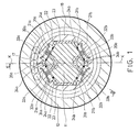
- Figure 1 is a schematical vertical sectional view of a variable-crown roll in accordance with the invention at the level of an end bearing of the roll.
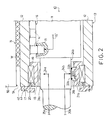
- Figure 2 is a partial sectional view of a roll as shown in Fig. 1 and of a counter-roll placed in nip contact with said roll, taken along the line II-II in Fig. 1.
- Referring to Figures 1 and 2, the variable-crown roll shown in them is denoted generally with the
reference numeral 10. In the ordinary way, the variable-crown roll 10 comprises a stationarycentral axle 11, on which theroll mantle 12 is arranged revolving. Between theroll mantle 12 and thecentral axle 11,hydraulic loading elements 14 are provided, which comprise hydraulic pistons fitted displaceably incylinder bores 15 formed into thecentral axle 11, glide shoes placed at the upper ends of said pistons being supported against theinner face 16 of theroll mantle 12. Thehydraulic loading elements 14 are loaded by means of a pressure medium, e.g. pressure fluid, against theinner face 16 of the roll mantle, which said pressure fluid is fed into thecylinder bores 15 in thehydraulic loading elements 14 to underneath the hydraulic pistons alongfluid ducts 15′. Thus, by means of thehydraulic loading elements 14, the profile of the nip N that can be formed by said variable-crown roll 10 with thecounter-roll 50 is adjusted, for saidhydraulic loading elements 14 are fitted to act substantially at the nip plane K-K of the nip N. For example, a paper web W or equivalent is arranged in the customary way to run through the nip N defined by the outer face of theroll mantle 12 of the variable-crown roll 10 and by theface 51 of thecounter-roll 50.End parts 40 are attached to the ends of theroll mantle 12 of the variable-crown roll 10, e.g., by means ofscrews 41. - The
roll mantle 12 of the variable-crown roll 10 is mounted rotatably substantially in the area of or at the proximity of both of its ends by means ofbearings 17 on saidstationary axle 11, and saidaxle 11 is supported on the frame of the device that includes the variable-crown roll 10 in accordance with the invention from outside the journalling points of theroll mantle 12. From outside, thebearings 17 are supported on a bearing face formed on theinner face 16 of the roll mantle, and the stationary inner part of the bearings consists of anannular part 18, along whose outer face the rolling members of thebearings 17 roll. The rolling members of thebearings 17 are placed on theannular part 18 in a groove, which are defined in the axial direction byrigidifiers inner rigidifier 19 in the axial direction, i.e. the first rigidifier, is stationary, whereas theouter rigidifier 20 in the axial direction, i.e. the second rigidifier, is preferably detachable, being appropriately attached to theannular part 18 by means of a screw attachment. Of course, the arrangement may also be reversed, in relation to that described above. - The
annular part 18 is supported on theaxle 11 of the variable-crown roll in accordance with the invention by means of power units by means of which the nip N can be both opened and closed and by means of which, moreover, loading forces can be applied to the ends of theroll mantle 12 optimally and in such a way that the entire regulating capacity of thehydraulic loading elements 14 placed within the journalling interspace of theroll mantle 12 remains available for compensation of local profile faults. Said power units comprisecylinder bores annular part 18, in which said cylinder boreshydraulic pistons central axle 11 of the variable-crown roll. Thus, thepower units bearing 17, and, as is shown in the figure, they are arranged so that their direction of effect diverges from the direction of the nip plane K-K. As can be seen in particular from Fig. 1, the power units are arranged in pairs and symmetrically relative the nip plane K-K, so that the straight lines of effect of the power units in each pair form an angle relative the nip plane K-K, whereby the resultant of the forces in the pair ofpower units bearing 17, two sets of power units are placed, of which one set, the pair ofpower units power units - Since the
pistons pistons axle 11. For this purpose,plane faces axle 11 facing thepistons piston plane face seals axial fluid ducts axle 11, as well asradial fluid ducts pistons seals pistons ducts piston pistons piston plane face seal piston roll mantle 12 of the variable-crown roll in accordance with the invention can be made to move, by means of the power units placed underneath thebearing 17, relative theaxle 11 without friction. - In order to ensure that the direction of the movement of the
roll mantle 12 relative theaxle 11 is parallel to the nip plane K-K, on theroll axle 11, at both sides of the nip plane K-K,glide faces 23 are provided, which are parallel to the nip plane K-K. Theglide faces 23 may be made, e.g., of a suitable bearing material, and they are, thus, fixed on theroll axle 11. In a corresponding way,guide faces 22 have been formed on theannular part 18, along which said guide faces 22 theglide faces 23 are fitted to glide when the position of theroll mantle 12 in relation to theaxle 11 is changed. Thus, saidfaces annular part 18 and theaxle 11 in relation to each other. - By means of the solution in accordance with the invention, the highly significant advantage is obtained that, by means of power units placed underneath the
bearing 17, a sufficiently high force is produced by means of a low pressure level. Thus, in a preferred embodiment, in thepower units bearing 17 becomes substantially better than in earlier solutions, for the distribution of pressure in thebearing 17 becomes more advantageous, because thepower units - Above, the invention has been described by way of example with reference to the figures in the accompanying drawing. The invention is, however, not confined to the exemplifying embodiment illustrated in the figures alone, but different details of the invention maY show variation within the scope of the inventive idea defined in the accompanying patent claims.
Claims (8)
Priority Applications (1)
| Application Number | Priority Date | Filing Date | Title |
|---|---|---|---|
| AT89850032T ATE99366T1 (en) | 1988-02-05 | 1989-02-03 | ROLLER WITH ADJUSTABLE BEND LINE. |
Applications Claiming Priority (2)
| Application Number | Priority Date | Filing Date | Title |
|---|---|---|---|
| FI880515A FI79177C (en) | 1988-02-05 | 1988-02-05 | BOEJNINGSREGLERAD VALS. |
| FI880515 | 1988-02-05 |
Publications (3)
| Publication Number | Publication Date |
|---|---|
| EP0332594A2 true EP0332594A2 (en) | 1989-09-13 |
| EP0332594A3 EP0332594A3 (en) | 1990-08-16 |
| EP0332594B1 EP0332594B1 (en) | 1993-12-29 |
Family
ID=8525853
Family Applications (1)
| Application Number | Title | Priority Date | Filing Date |
|---|---|---|---|
| EP89850032A Expired - Lifetime EP0332594B1 (en) | 1988-02-05 | 1989-02-03 | Variable-crown roll |
Country Status (5)
| Country | Link |
|---|---|
| EP (1) | EP0332594B1 (en) |
| CN (1) | CN1019032B (en) |
| AT (1) | ATE99366T1 (en) |
| DE (1) | DE68911718T2 (en) |
| FI (1) | FI79177C (en) |
Cited By (1)
| Publication number | Priority date | Publication date | Assignee | Title |
|---|---|---|---|---|
| EP0705938A2 (en) | 1994-09-15 | 1996-04-10 | Valmet Paper Machinery Inc. | Method and equipment for supporting a roll mantle in the direction |
Families Citing this family (20)
| Publication number | Priority date | Publication date | Assignee | Title |
|---|---|---|---|---|
| DK0803277T3 (en) * | 1993-01-13 | 2002-06-17 | Kansai Electric Power Co | Gas-liquid contact apparatus |
| DE4305371C2 (en) * | 1993-02-22 | 1995-11-23 | Kleinewefers Gmbh | Roller arrangement with a deflection compensation roller |
| US5329849A (en) * | 1993-06-11 | 1994-07-19 | Beloit Technologies, Inc. | Self-loading controlled crown roll |
| FI95062C (en) * | 1993-12-29 | 1995-12-11 | Valmet Paper Machinery Inc | Calendar |
| FI97565C (en) * | 1995-02-22 | 1997-01-10 | Valmet Paper Machinery Inc | Method for sliding the roller sheath of a tubular roller intended for a paper machine or equivalent and a tubular roller applying the method |
| FI98320C (en) * | 1994-03-09 | 1997-05-26 | Valmet Paper Machinery Inc | Method for sliding the roller sheath of a tubular roller intended for a paper machine or equivalent and a tubular roller applying the method |
| FI100481B (en) * | 1995-10-23 | 1997-12-15 | Valmet Corp | A method for controlling the temperature of the end regions of a sliding bearing ad roller sheath of a bending compensated roller |
| FI110014B (en) | 1996-10-23 | 2002-11-15 | Metso Paper Inc | Method for sliding the roller sheath of a preformed roller of a paper machine or its equivalent and a sliding roller |
| FI104100B1 (en) | 1998-06-10 | 1999-11-15 | Valmet Corp | Integrated paper machine |
| DE19947398C2 (en) * | 1999-10-01 | 2001-08-16 | Voith Paper Patent Gmbh | Deflection adjustment roller |
| DE10026939A1 (en) * | 1999-10-01 | 2001-12-13 | Voith Paper Patent Gmbh | Deflection adjustment roller |
| FI116091B (en) | 2000-04-12 | 2005-09-15 | Metso Paper Inc | A method for measuring plain bearing pressure in a fixed-shell deflection compensated roll |
| DE10050596A1 (en) | 2000-10-12 | 2002-04-18 | Voith Paper Patent Gmbh | Roller with an adjustable bending action, as a press roller, has hydrostatic mantle supports against the inner carrier in pairs flanking the press plane for an effective and controlled bending at high speeds |
| FI119524B (en) | 2006-10-12 | 2008-12-15 | Metso Paper Inc | Sealing device for the end of a paper / cardboard machine or finishing machine roller |
| FI20075658L (en) | 2007-09-20 | 2009-03-21 | Metso Paper Inc | Arrangement in a deflection-compensated roll of a paper/cardboard machine |
| DE102008046150A1 (en) | 2008-06-13 | 2009-12-17 | Metso Paper, Inc. | Method for prevention of bar ring oscillations in roll gap construction of manufacturing machine for fiber course material, involves arranging lower rolls and upper rolls one above other |
| DE102008045850A1 (en) | 2008-09-05 | 2010-03-11 | Metso Paper, Inc. | Roller gap construction's bar ring-vibrations preventing method for calender e.g. two-roller calender, of manufacturing machine, involves holding piston of hydraulic cylinders in distance to end position in cylinders during operation |
| ITFI20130106A1 (en) * | 2013-05-09 | 2014-11-10 | Toscotec S P A | SHOE PRESS. |
| CN105987084B (en) * | 2015-02-11 | 2018-05-29 | 沈阳工业大学 | The anti-gas bubble pulsation percussion mechanism of naval vessels main shaft |
| CN110314739B (en) * | 2019-07-16 | 2021-01-05 | 杨峰 | Roller sleeve |
Family Cites Families (7)
| Publication number | Priority date | Publication date | Assignee | Title |
|---|---|---|---|---|
| US3494675A (en) * | 1968-06-11 | 1970-02-10 | Farrel Corp | Controlled deflection roll |
| US3587152A (en) * | 1968-06-12 | 1971-06-28 | Usm Corp | Controlled deflection roll |
| DE2655894A1 (en) * | 1976-12-09 | 1978-06-22 | Valmet Oy | ROLLER WITH CONTROLLABLE DEFLECTION |
| DE2919748C2 (en) * | 1979-05-10 | 1983-08-18 | Escher Wyss AG, Zürich | Rolling device for rolling web-shaped materials |
| DE3131799C2 (en) * | 1981-08-12 | 1984-08-30 | Kleinewefers Gmbh, 4150 Krefeld | Roller press for paper and similar webs, in particular calenders |
| DE3539428A1 (en) * | 1985-11-07 | 1987-05-21 | Kleinewefers Gmbh | DEFORMING CONTROL ROLLER |
| FI75217C (en) * | 1986-11-10 | 1988-05-09 | Valmet Oy | BOEJNINGSREGLERAD VALS. |
-
1988
- 1988-02-05 FI FI880515A patent/FI79177C/en active IP Right Grant
-
1989
- 1989-02-03 AT AT89850032T patent/ATE99366T1/en not_active IP Right Cessation
- 1989-02-03 EP EP89850032A patent/EP0332594B1/en not_active Expired - Lifetime
- 1989-02-03 DE DE89850032T patent/DE68911718T2/en not_active Expired - Lifetime
- 1989-02-04 CN CN89100638A patent/CN1019032B/en not_active Expired
Cited By (1)
| Publication number | Priority date | Publication date | Assignee | Title |
|---|---|---|---|---|
| EP0705938A2 (en) | 1994-09-15 | 1996-04-10 | Valmet Paper Machinery Inc. | Method and equipment for supporting a roll mantle in the direction |
Also Published As
| Publication number | Publication date |
|---|---|
| CN1036609A (en) | 1989-10-25 |
| EP0332594A3 (en) | 1990-08-16 |
| FI79177B (en) | 1989-07-31 |
| EP0332594B1 (en) | 1993-12-29 |
| CN1019032B (en) | 1992-11-11 |
| DE68911718D1 (en) | 1994-02-10 |
| DE68911718T2 (en) | 1994-04-28 |
| ATE99366T1 (en) | 1994-01-15 |
| FI880515A0 (en) | 1988-02-05 |
| FI79177C (en) | 1989-11-10 |
Similar Documents
| Publication | Publication Date | Title |
|---|---|---|
| EP0332594B1 (en) | Variable-crown roll | |
| US4757585A (en) | Variable-crown roll | |
| EP0848107B1 (en) | Calender for calendering of a paper web | |
| EP0241442A2 (en) | Method for controlling the deflection of an adjustable-crown roll as well as a paper machine roll wherein the method is applied | |
| US4856154A (en) | Method and device in an adjustable crown roll | |
| EP0373942B1 (en) | Support arrangement for a variable-crown roll | |
| US5590593A (en) | Mounting arrangement for calendar rolls in a calender | |
| EP0897484B1 (en) | Hydrostatic glide bearing for a roll or equivalent | |
| CA2147730A1 (en) | Roll for a papermaking machine | |
| US4194446A (en) | Rolls, such as filled calender rolls, having deflection compensation | |
| US4747195A (en) | Roll for use in a paper machine | |
| CA2198229A1 (en) | Position control for self-loading roll | |
| CA1070535A (en) | Deflection-compensated, preferably soft-surface roll for use in a calender | |
| US4856155A (en) | Method and device in an adjustable-crown roll | |
| US4850088A (en) | Self-loading controlled deflection roll | |
| US5896813A (en) | Gradient calender | |
| EP0886696A1 (en) | A tubular roll provided with hydraulically loaded glide bearings | |
| US4757586A (en) | Glide-shoe arrangement for a variable-crown roll | |
| FI81184C (en) | BOEJNINGSKOMPENSERAD VALS. | |
| FI80772C (en) | FOERFARANDE VID EN BOEJNINGSREGLERAD VALS OCH EN BOEJNINGSREGLERAD VALS. | |
| FI82535B (en) | Method for measurement and adjustment of the position of the roll shell of a bend-adjusted roll | |
| CA2249382C (en) | Hydrostatic glide bearing for a roll or equivalent | |
| FI98319C (en) | A bend adjustable roll and method of controlling the load of a bend adjustable roll | |
| FI74068C (en) | FOERFARANDE OCH ANORDNING VID EN BOEJNINGSKOMPENSERAD ELLER -REGLERAD VALS I EN PAPPERSMASKIN. | |
| WO2001021889A1 (en) | Method and arrangement for control of rolls in a calender |
Legal Events
| Date | Code | Title | Description |
|---|---|---|---|
| PUAI | Public reference made under article 153(3) epc to a published international application that has entered the european phase |
Free format text: ORIGINAL CODE: 0009012 |
|
| AK | Designated contracting states |
Kind code of ref document: A2 Designated state(s): AT DE FR GB IT SE |
|
| PUAL | Search report despatched |
Free format text: ORIGINAL CODE: 0009013 |
|
| AK | Designated contracting states |
Kind code of ref document: A3 Designated state(s): AT DE FR GB IT SE |
|
| 17P | Request for examination filed |
Effective date: 19900928 |
|
| 17Q | First examination report despatched |
Effective date: 19920507 |
|
| GRAA | (expected) grant |
Free format text: ORIGINAL CODE: 0009210 |
|
| AK | Designated contracting states |
Kind code of ref document: B1 Designated state(s): AT DE FR GB IT SE |
|
| REF | Corresponds to: |
Ref document number: 99366 Country of ref document: AT Date of ref document: 19940115 Kind code of ref document: T |
|
| REF | Corresponds to: |
Ref document number: 68911718 Country of ref document: DE Date of ref document: 19940210 |
|
| ITF | It: translation for a ep patent filed | ||
| ET | Fr: translation filed | ||
| PLBE | No opposition filed within time limit |
Free format text: ORIGINAL CODE: 0009261 |
|
| STAA | Information on the status of an ep patent application or granted ep patent |
Free format text: STATUS: NO OPPOSITION FILED WITHIN TIME LIMIT |
|
| 26N | No opposition filed | ||
| EAL | Se: european patent in force in sweden |
Ref document number: 89850032.7 |
|
| REG | Reference to a national code |
Ref country code: GB Ref legal event code: IF02 |
|
| PGFP | Annual fee paid to national office [announced via postgrant information from national office to epo] |
Ref country code: GB Payment date: 20020115 Year of fee payment: 14 |
|
| PGFP | Annual fee paid to national office [announced via postgrant information from national office to epo] |
Ref country code: SE Payment date: 20020204 Year of fee payment: 14 |
|
| PGFP | Annual fee paid to national office [announced via postgrant information from national office to epo] |
Ref country code: FR Payment date: 20020207 Year of fee payment: 14 |
|
| PG25 | Lapsed in a contracting state [announced via postgrant information from national office to epo] |
Ref country code: GB Free format text: LAPSE BECAUSE OF NON-PAYMENT OF DUE FEES Effective date: 20030203 |
|
| PG25 | Lapsed in a contracting state [announced via postgrant information from national office to epo] |
Ref country code: SE Free format text: LAPSE BECAUSE OF NON-PAYMENT OF DUE FEES Effective date: 20030204 |
|
| GBPC | Gb: european patent ceased through non-payment of renewal fee | ||
| EUG | Se: european patent has lapsed | ||
| PG25 | Lapsed in a contracting state [announced via postgrant information from national office to epo] |
Ref country code: FR Free format text: LAPSE BECAUSE OF NON-PAYMENT OF DUE FEES Effective date: 20031031 |
|
| REG | Reference to a national code |
Ref country code: FR Ref legal event code: ST |
|
| PG25 | Lapsed in a contracting state [announced via postgrant information from national office to epo] |
Ref country code: IT Free format text: LAPSE BECAUSE OF NON-PAYMENT OF DUE FEES Effective date: 20050203 |
|
| PGFP | Annual fee paid to national office [announced via postgrant information from national office to epo] |
Ref country code: DE Payment date: 20080219 Year of fee payment: 20 |
|
| PGFP | Annual fee paid to national office [announced via postgrant information from national office to epo] |
Ref country code: AT Payment date: 20080215 Year of fee payment: 20 |