EP0332690B1 - Verbesserter flussmeter mit druckmessung - Google Patents
Verbesserter flussmeter mit druckmessung Download PDFInfo
- Publication number
- EP0332690B1 EP0332690B1 EP88908607A EP88908607A EP0332690B1 EP 0332690 B1 EP0332690 B1 EP 0332690B1 EP 88908607 A EP88908607 A EP 88908607A EP 88908607 A EP88908607 A EP 88908607A EP 0332690 B1 EP0332690 B1 EP 0332690B1
- Authority
- EP
- European Patent Office
- Prior art keywords
- pressure
- source
- fluid
- volume
- reservoir
- Prior art date
- Legal status (The legal status is an assumption and is not a legal conclusion. Google has not performed a legal analysis and makes no representation as to the accuracy of the status listed.)
- Expired - Lifetime
Links
- 238000009530 blood pressure measurement Methods 0.000 title description 2
- 239000012530 fluid Substances 0.000 claims abstract description 103
- 238000005259 measurement Methods 0.000 claims abstract description 71
- 230000008859 change Effects 0.000 claims abstract description 34
- 238000004891 communication Methods 0.000 claims abstract description 23
- 238000005086 pumping Methods 0.000 claims abstract description 21
- 230000000694 effects Effects 0.000 claims abstract description 5
- 230000000295 complement effect Effects 0.000 claims abstract description 3
- 230000008867 communication pathway Effects 0.000 claims description 21
- 239000012528 membrane Substances 0.000 claims description 19
- 230000004913 activation Effects 0.000 claims description 11
- 230000037361 pathway Effects 0.000 claims description 3
- 238000012544 monitoring process Methods 0.000 claims 7
- 230000002463 transducing effect Effects 0.000 claims 4
- 238000006073 displacement reaction Methods 0.000 description 12
- 238000001802 infusion Methods 0.000 description 8
- 238000013459 approach Methods 0.000 description 4
- 239000000463 material Substances 0.000 description 2
- 239000002184 metal Substances 0.000 description 2
- 229910052751 metal Inorganic materials 0.000 description 2
- 238000000034 method Methods 0.000 description 2
- 230000004044 response Effects 0.000 description 2
- 230000001594 aberrant effect Effects 0.000 description 1
- 230000009471 action Effects 0.000 description 1
- 230000003213 activating effect Effects 0.000 description 1
- 230000032683 aging Effects 0.000 description 1
- 230000008901 benefit Effects 0.000 description 1
- 230000033228 biological regulation Effects 0.000 description 1
- 238000002512 chemotherapy Methods 0.000 description 1
- 230000003247 decreasing effect Effects 0.000 description 1
- 238000013461 design Methods 0.000 description 1
- 238000001514 detection method Methods 0.000 description 1
- 238000010586 diagram Methods 0.000 description 1
- 229940079593 drug Drugs 0.000 description 1
- 239000003814 drug Substances 0.000 description 1
- 238000005516 engineering process Methods 0.000 description 1
- 230000008595 infiltration Effects 0.000 description 1
- 238000001764 infiltration Methods 0.000 description 1
- 238000001990 intravenous administration Methods 0.000 description 1
- 230000001788 irregular Effects 0.000 description 1
- 150000002739 metals Chemical class 0.000 description 1
- 238000013508 migration Methods 0.000 description 1
- 230000005012 migration Effects 0.000 description 1
- 230000003287 optical effect Effects 0.000 description 1
- 238000010926 purge Methods 0.000 description 1
- 230000009885 systemic effect Effects 0.000 description 1
- 231100000331 toxic Toxicity 0.000 description 1
- 230000002588 toxic effect Effects 0.000 description 1
- 238000011144 upstream manufacturing Methods 0.000 description 1
- 238000013022 venting Methods 0.000 description 1
- 230000003612 virological effect Effects 0.000 description 1
- 238000005303 weighing Methods 0.000 description 1
Images
Classifications
-
- A—HUMAN NECESSITIES
- A61—MEDICAL OR VETERINARY SCIENCE; HYGIENE
- A61M—DEVICES FOR INTRODUCING MEDIA INTO, OR ONTO, THE BODY; DEVICES FOR TRANSDUCING BODY MEDIA OR FOR TAKING MEDIA FROM THE BODY; DEVICES FOR PRODUCING OR ENDING SLEEP OR STUPOR
- A61M5/00—Devices for bringing media into the body in a subcutaneous, intra-vascular or intramuscular way; Accessories therefor, e.g. filling or cleaning devices, arm-rests
- A61M5/14—Infusion devices, e.g. infusing by gravity; Blood infusion; Accessories therefor
- A61M5/168—Means for controlling media flow to the body or for metering media to the body, e.g. drip meters, counters ; Monitoring media flow to the body
- A61M5/16804—Flow controllers
- A61M5/16813—Flow controllers by controlling the degree of opening of the flow line
-
- A—HUMAN NECESSITIES
- A61—MEDICAL OR VETERINARY SCIENCE; HYGIENE
- A61M—DEVICES FOR INTRODUCING MEDIA INTO, OR ONTO, THE BODY; DEVICES FOR TRANSDUCING BODY MEDIA OR FOR TAKING MEDIA FROM THE BODY; DEVICES FOR PRODUCING OR ENDING SLEEP OR STUPOR
- A61M5/00—Devices for bringing media into the body in a subcutaneous, intra-vascular or intramuscular way; Accessories therefor, e.g. filling or cleaning devices, arm-rests
- A61M5/14—Infusion devices, e.g. infusing by gravity; Blood infusion; Accessories therefor
- A61M5/168—Means for controlling media flow to the body or for metering media to the body, e.g. drip meters, counters ; Monitoring media flow to the body
- A61M5/16804—Flow controllers
- A61M5/16809—Flow controllers by repeated filling and emptying of an intermediate volume
-
- A—HUMAN NECESSITIES
- A61—MEDICAL OR VETERINARY SCIENCE; HYGIENE
- A61M—DEVICES FOR INTRODUCING MEDIA INTO, OR ONTO, THE BODY; DEVICES FOR TRANSDUCING BODY MEDIA OR FOR TAKING MEDIA FROM THE BODY; DEVICES FOR PRODUCING OR ENDING SLEEP OR STUPOR
- A61M5/00—Devices for bringing media into the body in a subcutaneous, intra-vascular or intramuscular way; Accessories therefor, e.g. filling or cleaning devices, arm-rests
- A61M5/14—Infusion devices, e.g. infusing by gravity; Blood infusion; Accessories therefor
- A61M5/168—Means for controlling media flow to the body or for metering media to the body, e.g. drip meters, counters ; Monitoring media flow to the body
- A61M5/16831—Monitoring, detecting, signalling or eliminating infusion flow anomalies
- A61M5/16854—Monitoring, detecting, signalling or eliminating infusion flow anomalies by monitoring line pressure
- A61M5/16859—Evaluation of pressure response, e.g. to an applied pulse
-
- A—HUMAN NECESSITIES
- A61—MEDICAL OR VETERINARY SCIENCE; HYGIENE
- A61M—DEVICES FOR INTRODUCING MEDIA INTO, OR ONTO, THE BODY; DEVICES FOR TRANSDUCING BODY MEDIA OR FOR TAKING MEDIA FROM THE BODY; DEVICES FOR PRODUCING OR ENDING SLEEP OR STUPOR
- A61M5/00—Devices for bringing media into the body in a subcutaneous, intra-vascular or intramuscular way; Accessories therefor, e.g. filling or cleaning devices, arm-rests
- A61M5/36—Devices for bringing media into the body in a subcutaneous, intra-vascular or intramuscular way; Accessories therefor, e.g. filling or cleaning devices, arm-rests with means for eliminating or preventing injection or infusion of air into body
- A61M5/365—Air detectors
-
- F—MECHANICAL ENGINEERING; LIGHTING; HEATING; WEAPONS; BLASTING
- F04—POSITIVE - DISPLACEMENT MACHINES FOR LIQUIDS; PUMPS FOR LIQUIDS OR ELASTIC FLUIDS
- F04B—POSITIVE-DISPLACEMENT MACHINES FOR LIQUIDS; PUMPS
- F04B43/00—Machines, pumps, or pumping installations having flexible working members
- F04B43/02—Machines, pumps, or pumping installations having flexible working members having plate-like flexible members, e.g. diaphragms
- F04B43/04—Pumps having electric drive
- F04B43/043—Micropumps
-
- F—MECHANICAL ENGINEERING; LIGHTING; HEATING; WEAPONS; BLASTING
- F16—ENGINEERING ELEMENTS AND UNITS; GENERAL MEASURES FOR PRODUCING AND MAINTAINING EFFECTIVE FUNCTIONING OF MACHINES OR INSTALLATIONS; THERMAL INSULATION IN GENERAL
- F16K—VALVES; TAPS; COCKS; ACTUATING-FLOATS; DEVICES FOR VENTING OR AERATING
- F16K31/00—Actuating devices; Operating means; Releasing devices
- F16K31/004—Actuating devices; Operating means; Releasing devices actuated by piezoelectric means
- F16K31/005—Piezoelectric benders
-
- G—PHYSICS
- G01—MEASURING; TESTING
- G01F—MEASURING VOLUME, VOLUME FLOW, MASS FLOW OR LIQUID LEVEL; METERING BY VOLUME
- G01F1/00—Measuring the volume flow or mass flow of fluid or fluent solid material wherein the fluid passes through a meter in a continuous flow
- G01F1/05—Measuring the volume flow or mass flow of fluid or fluent solid material wherein the fluid passes through a meter in a continuous flow by using mechanical effects
- G01F1/34—Measuring the volume flow or mass flow of fluid or fluent solid material wherein the fluid passes through a meter in a continuous flow by using mechanical effects by measuring pressure or differential pressure
-
- G—PHYSICS
- G01—MEASURING; TESTING
- G01P—MEASURING LINEAR OR ANGULAR SPEED, ACCELERATION, DECELERATION, OR SHOCK; INDICATING PRESENCE, ABSENCE, OR DIRECTION, OF MOVEMENT
- G01P13/00—Indicating or recording presence, absence, or direction, of movement
- G01P13/0006—Indicating or recording presence, absence, or direction, of movement of fluids or of granulous or powder-like substances
- G01P13/0066—Indicating or recording presence, absence, or direction, of movement of fluids or of granulous or powder-like substances by using differences of pressure in the fluid
-
- A—HUMAN NECESSITIES
- A61—MEDICAL OR VETERINARY SCIENCE; HYGIENE
- A61M—DEVICES FOR INTRODUCING MEDIA INTO, OR ONTO, THE BODY; DEVICES FOR TRANSDUCING BODY MEDIA OR FOR TAKING MEDIA FROM THE BODY; DEVICES FOR PRODUCING OR ENDING SLEEP OR STUPOR
- A61M5/00—Devices for bringing media into the body in a subcutaneous, intra-vascular or intramuscular way; Accessories therefor, e.g. filling or cleaning devices, arm-rests
- A61M5/14—Infusion devices, e.g. infusing by gravity; Blood infusion; Accessories therefor
- A61M2005/1401—Functional features
- A61M2005/1403—Flushing or purging
-
- A—HUMAN NECESSITIES
- A61—MEDICAL OR VETERINARY SCIENCE; HYGIENE
- A61M—DEVICES FOR INTRODUCING MEDIA INTO, OR ONTO, THE BODY; DEVICES FOR TRANSDUCING BODY MEDIA OR FOR TAKING MEDIA FROM THE BODY; DEVICES FOR PRODUCING OR ENDING SLEEP OR STUPOR
- A61M2205/00—General characteristics of the apparatus
- A61M2205/15—Detection of leaks
-
- A—HUMAN NECESSITIES
- A61—MEDICAL OR VETERINARY SCIENCE; HYGIENE
- A61M—DEVICES FOR INTRODUCING MEDIA INTO, OR ONTO, THE BODY; DEVICES FOR TRANSDUCING BODY MEDIA OR FOR TAKING MEDIA FROM THE BODY; DEVICES FOR PRODUCING OR ENDING SLEEP OR STUPOR
- A61M39/00—Tubes, tube connectors, tube couplings, valves, access sites or the like, specially adapted for medical use
- A61M39/22—Valves or arrangement of valves
- A61M39/26—Valves closing automatically on disconnecting the line and opening on reconnection thereof
-
- Y—GENERAL TAGGING OF NEW TECHNOLOGICAL DEVELOPMENTS; GENERAL TAGGING OF CROSS-SECTIONAL TECHNOLOGIES SPANNING OVER SEVERAL SECTIONS OF THE IPC; TECHNICAL SUBJECTS COVERED BY FORMER USPC CROSS-REFERENCE ART COLLECTIONS [XRACs] AND DIGESTS
- Y10—TECHNICAL SUBJECTS COVERED BY FORMER USPC
- Y10S—TECHNICAL SUBJECTS COVERED BY FORMER USPC CROSS-REFERENCE ART COLLECTIONS [XRACs] AND DIGESTS
- Y10S128/00—Surgery
- Y10S128/13—Infusion monitoring
Definitions
- the present invention relates generally to systems for controlling fluid flow, and in particular to medical infusion technology, although other embodiments are discussed below.
- the present invention provides a system for measuring flow of a fluid through a line.
- a region of fluid along the line is isolated from pressure effects outside of the region.
- a source chamber contains a measurement gas in communication with the isolated region, such that the source chamber and the isolated region together define a fixed volume, and such that a change in volume of fluid in the isolated region produces a complementary change in the volume of the source chamber with a resulting chamber in the pressure of the measurement gas contained in the source chamber.
- a reservoir chamber in communication with the source chamber for containing a known volume of measurement gas, and means for pumping measurement gas from the reservoir chamber into the source chamber. The pressure of the measurement gas in the reservoir chamber and the pressure of the measurement fluid in the source chamber are monitored as fluid flows into and out of the region. This pressure data is then analyzed to determine the volume of fluid in the isolated region.
- the present invention precisely measures discrete volume increments of fluid along a line by taking advantage of the known physical relationship between the pressure and volume of a gas. This is accomplished by isolating a region of the line and housing that region in communication with a measurement gas such that the isolated region of fluid and the measurement gas occupy a fixed and ascertainable volume. Thus, the movement of fluid into and out of the isolated region produces a corresponding change in the pressure of the measurement gas.
- the pressure of the measurement gas is monitored by a transducer, and the resulting data is used to compute the volume of fluid delivered, using methods described below.
- a system of this type must include calibration means for establishing reference quantities against which later measured quanitities can be compared.
- One approach to calibration is disclosed in US-A-4808161 and EP-A-0262182 which are hereby incorporated by reference and neither of which is published within the meaning of Article 5A(2)EPC.
- the systems disclosed therein are calibrated by measuring the pressure of the measurement gas during a calibration cycle, during which the system, in the absence of fluid flow, induces a known decrease in volume of the measurement gas.
- the system measures the pressure of the measurement gas during the flow of volume increments of fluid into and out of the isolated region.
- the system uses various disclosed physical and mathematical relationships, the system then computes the volume of fluid delivered using the calibration data together with pressure measurements taken during fluid flow.
- the earlier device proved to be extremely accurate at low rates of fluid delivery, but was not totally free from error.
- a certain percentage of error was inherent in the mechanical creation of a precise volume displacement.
- error was found to be caused by a certain bowing out of the folds, which was found to be inevitable.
- any precision could be affected by the aging of system.
- Other embodiments would still require precise mechanical displacement and generally good seal arrangement along the moving mechnical interface.
- the present device solves these problems of the earlier device by employing pressure displacement instead of the precise volume displacement of the earlier system.
- pressure displacement solves many of the problems of the earlier device.
- the use of pressure displacement does not require a precise mechanical displacement, thus eliminating the errors associated therewith.
- the system may utilize pressure displacement in such a fashion that the presence of back pressure does not necessitate significantly more pumping that would be the case in the absence of back pressure.
- the system can be configured to compensate for a wide range of back pressures, including situations where back pressure exceeds fluid reservoir head pressure.
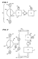
- Fig. 1 shows a schematic drawing of a simplified embodiment of the present invention.
- the system includes two chambers, reservoir chamber 11 and source chamber 12 for housing a measurement gas.
- These chambers may be constructed of a rigid plastic using methods known in the art, although a wide variety of other materials, including metals, may also be suitable, the principal desideratum being that the chambers maintain a fixed volume regardless of the pressure of the measurement gas. It is thus contemplated that the volume of reservoir chamber 11 in this embodiment is known, although the volume could be determined heuristically in the course of initial calibration of the system.
- Each chamber has an associated pressure transducer 13, 14.
- the two chambers are connected, but are separated by a pump arrangement 111 that can move measurement gas contained in reservoir chamber 11 into source chamber 12 with a resulting decrease in pressure in the reservoir chamber and an increase in pressure in the source chamber.
- the pump arrangement 111 also serves to prevent backflow of measurement gas.
- the source chamber is in communication with a region 15 of the fluid line 16 that can be isolated by valves 17 and 18 from fluid pressure effects elsewhere in the line. Communication between the line fluid and the measurement gas is afforded through flexible membrane 19.
- a bulge 110 is provided in the region. The bulge serves two purposes. First, the bulge allows a greater amount of line fluid to impinge against the measurement gas, thus increasing the pressure communication between the line fluid and the measurement gas. Second, the bulge, because of its substantially spherical shape, provides maximum radial rigidity, thus preventing the isolated region from becoming distorted as a result of high measurement gas pressure.
- valve 17 or valve 18 when either valve 17 or valve 18 is closed, movement of fluid into or out of the isolated region 15 will, via flexible membrane 19, decrease or increase the volume of the measurement gas in the source chamber, with a resulting change in the pressure of the measurement gas.
- ⁇ V S ( ⁇ P R o V R / ⁇ P S o ) [ ⁇ P S /(P S + ⁇ P S )]
- Total fluid delivered can be calculated by summing each individual ⁇ V S , which can be expressed by the following formula:
- steps E, F, and G may be repeated a desired number of times as a subcycle within larger cycle of steps B through G.
- Fig. 2 shows a schematic diagram of a preferred embodiment of the present invention.
- This embodiment involves a slightly different arrangement for placing the reservoir chamber 11 and the source chamber 12 in communication with each other and with the isolated region of the fluid line.
- the embodiment of Fig. 2 provides a communication pathway 21, gated by valve 22, to the isolated region.
- the pathway 23 between the source chamber 12 and the isolated region 15 is gated by valve 24.
- it is possible to circulate measurement fluid around a closed circuit, namely from reservoir chamber 11 to source chamber 12 into the bulge 110 and then back to the reservoir chamber 11, with a resulting economy of operation.
- a measurement gas such as air
- a measurement gas such as air
- valves 17, 18, 22 and 24 are closed.
- Valves 17 and 22 are then opened.
- the opening of valve 17 allows fluid to flow into the isolated region.
- the opening of valve 22 defines two separate volumes. One of these volumes is the sum of the volumes of the reservoir chamber 11 and communication pathway 21 up to flexible membrane 19. The second is the volume of source chamber 12 plus the volume of that portion of communication pathway 23 up to valve 24. The pressures of measurement gas associated with these two volumes are then measured and recorded.
- Valve 17 is then closed. Pump 25 is then run to create a pressure differential between the reservoir chamber and the source chamber. Then valve 22 is closed. At this point, because fluid flow has been stopped, the pressure of the measurement gas is the same on either side of valve 22, now closed. Thus, either pressure quantity could be measured.
- transducer 13 measures the pressure between the valve and the flexible membrane.
- the pressure P S of the source chamber up to valve 24, which is closed, and the pressure P (R+D) of the reservoir chamber, including communication pathway 21 up to flexible membrane 19, are measured before and after activation of pump 25 to to calculate ⁇ P S o and ⁇ P (R+D) o : (14) ⁇ P S o ⁇ P Sf o - P Si o (15) ⁇ P (R+D) o ⁇ P (R+D)f o - P (R+D)i o
- P Si which is the pressure of the source chamber before opening valve 24, is remeasured. If there has been no leak in the system, or other error, P Si should be equal to P sf o , which was the pressure measured after activation of pump 25 but before fluid flow. Valve 24 is then opened.
- V D o ⁇ P Scal o V S o / ⁇ P (R+D) o -V S This V D o should, if the system is operating properly, be equal to V D o above. If the two values for V D o are not equal, this could indicate various system errors, including leakage of measurement gas.
- the operation of the device depicted in Fig. 2 and described above can be summed up in the following steps:
- measurement gas follows a cyclical travel pattern. Measurement gas is pumped from the reservoir chamber into the source chamber. The repeated opening and closing of valves 22 and 24 result in the migration of measurement gas from the source chamber back into the reservoir chamber. It will thus be seen that the system displays an innovative economy of design, since no venting or other means of pressure balancing is required.
- the present invention can be configured to operate as a pump. There is a point in the operation cycle when valves 18 and 24 are both open. Becuase the measurement gas in source chamber 12 is at a relatively high pressure, fluid will tend to be pushed out of the isolated region. If a high enough pressure differential is created between the measurement gas in the source chamber and the measurement gas in the reservoir chamber, significant pumping action will result.
- the pressure differential can also be used to solve the problem of back pressure. It will be seen that the system will provide data as to fluid flow through the line even if back pressure results in no flow at all, or in backflow. These phenomena will produce a corresponding change in measurement gas pressure, which in turn will yield a zero or negative volume increment using the calculations disclosed above. This information can be used to compensate for downstream pressure conditions.
- the microprocessor, or other controlling device can be programmed to increase the pressure differential where small or negative flows are detected. The pressure differential would be increased by activating pump 25 as needed.
- steps J through L may be repeated a desired number of times as a subcycle within a larger cycle of steps B through L.
- the operating pressure of source chamber 12 is kept at approximately that of the line pressure at valve 17, the system may be operated in a controller mode.
- Fig. 2 It is contemplated to construct the embodiment of Fig. 2 out of rigid plastic, arranging the chambers and pathways in such a way that the final structure can be housed in a block configuration, although other materials, including metal, and configurations, known to practitioners of ordinary skill in the art, are also be within the scope of the present invention, as defined by the following claims.
Landscapes
- Health & Medical Sciences (AREA)
- Engineering & Computer Science (AREA)
- Heart & Thoracic Surgery (AREA)
- Hematology (AREA)
- Veterinary Medicine (AREA)
- Public Health (AREA)
- General Health & Medical Sciences (AREA)
- Vascular Medicine (AREA)
- Anesthesiology (AREA)
- Biomedical Technology (AREA)
- Animal Behavior & Ethology (AREA)
- Life Sciences & Earth Sciences (AREA)
- General Engineering & Computer Science (AREA)
- Physics & Mathematics (AREA)
- Mechanical Engineering (AREA)
- General Physics & Mathematics (AREA)
- Emergency Medicine (AREA)
- Fluid Mechanics (AREA)
- Infusion, Injection, And Reservoir Apparatuses (AREA)
- Measuring Volume Flow (AREA)
- Reciprocating Pumps (AREA)
- Measuring Fluid Pressure (AREA)
Claims (13)
- Ein System zum Steuern bzw. Regeln der Strömung eines Fluids durch eine Leitung (16), das System umfaßt:
Ein Spendemittel (17, 18) zum Isolieren eines Bereichs (15) der Leitung von Druckeffekten in der Leitung außerhalb des Bereichs, wobei der Bereich einen Eingang und einen Ausgang für das Fluid hat, und zum wiederholten Spenden von Volumeninkrementen des Fluids in den und aus dem Bereich;
ein Quellenmittel (12) zum Enthalten eines Steuer- bzw. Regelgases in Verbindung mit dem isolierten Bereich (15) und derart, daß eine Änderung im Volumen des Fluids in den isolierten Bereich eine komplementäre Änderung in dem Volumen des Quellenmittels mit einer resultierenden Änderung in dem Druck des Steuer- bzw. Regelgases, das in dem Quellenmittel enthalten ist, erzeugt;
ein Pumpmittel (111);
und ein Steuer- bzw. Regelmittel;
gekennzeichnet-
dadurch, daß das Quellenmittel (12) und der isolierte Bereich (15) zusammen ein festes Volumen definieren;
durch ein Reservoirmittel (11) in Verbindung mit dem Quellenmittel (12) zum Enthalten eines bekannten Volumens an Steuer- bzw. Regelgas;
dadurch, daß das Pumpmittel (111) dahingehend betreibbar ist, daß es eine Quantität des Steuer- bzw. Regelgases zwischen dem Reservoirmittel (11) und dem Quellenmittel (12) bewegt, so daß dadurch Änderungen in dem Druck des Steuer- bzw. Regelgases, das in dem Reservoirmittel enthalten ist, und dem Steuer- bzw. Regelgas, das in dem Quellenmittel enthalten ist, erzeugt werden;
durch Drucküberwachungsmittel (13, 14) zum Erzeugen von Daten, die sich auf den Druck des Steuer- bzw. Regelgases in dem Quellenmittel (12) und des Steuer- bzw. Regelgases in dem Reservoirmittel (11) beziehen, und
dadurch, daß das Steuer- bzw. Regelmittel in Verbindung mit den Drucküberwachungsmitteln (13, 14), dem Pumpmittel (111) und dem Spendemittel (17, 18) ist zum Bewirken, daß das Spendemittel Fluid in bestimmbaren Inkrementen, basierend auf Daten von den Drucküberwachungsmitteln, die an vorbestimmten Stellen während eines Kalibrierungs- und Spendezyklus genommen worden sind, spendet. - Ein System zum Steuern bzw. Regeln der Strömung eines Fluids durch eine Leitung (16), das System umfaßt:
Ein Spendemittel (17, 18) zum Isolieren eines Bereichs (15) der Leitung von Druckeffekten in der Leitung außerhalb des Bereichs, wobei der Bereich einen Eingang und einen Ausgang für das Fluid hat, und zum wiederholten Spenden von Volumeninkrementen des Fluids in den und aus dem Bereich;
eine Quellenkammer zum Enthalten eines ersten Volumens von Steuer- bzw. Regelgas;
einen Quellenverbindungsweg (23) zwischen der Quellenkammer (12) und dem isolierten Bereich (15);
ein Pumpmittel (25);
und ein Steuer- bzw. Regelmittel;
gekennzeichnet-
durch eine Reservoirkammer (11) in Verbindung mit dem Quellenkammer (12) zum Enthalten eines zweiten Volumens an Steuer- bzw. Regelgas;
dadurch, daß das Pumpmittel (111) dahingehend betreibbar ist, daß es eine Quantität an Steuer- bzw. Regelgases zwischen der Reservoirkammer (11) und der Quellenkammer (12) bewegt, so daß dadurch Änderungen in dem Druck des Steuer- bzw. Regelgases in der Reservoirkammer und in dem Druck des Steuer- bzw. Regelgases, das in der Quellenkammer enthalten ist, erzeugt werden;
durch einen Reservoirverbindungsweg (21) zwischen der Reservoirkammer (11) und dem isolierten Bereich (15), wobei der Quellenverbindungsweg (23) und der Reservoirverbindungsweg (21) sich an einer gewissen Stelle entlang jedem jeweiligen Weg vereinigen, um einen gemeinsamen Verbindungsweg zu bilden, der zu dem isolierten Bereich (15) führt;
ein Quellenventilmittel (24) zum Öffnen und Schließen des Quellenverbindungswegs (23);
ein Reservoirventilmittel (22) zum Öffnen und Schließen des Reservoirverbindungswegs (21);
der isolierte Bereich (15), die Quellenkammer (12), die Reservoirkammer (11), der Quellenverbindungsweg (23), der Reservoirverbindungsweg (21) und der gemeinsame Verbindungsweg sind so in Beziehung zueinander angeordnet, daß sie zusammen ein festes Volumen definieren, und derart, daß eine Änderung im Volumen des Fluids in dem isolierten Bereich eine korrelative Änderung im Druck in dem gemeinsamen Verbindungsweg und in jeder anderen Umschließung, die in Druckverbindung mit dem gemeinsamen Verbindungsweg ist, erzeugt;
ein erstes Druckumwandlungsmittel (13) in Druckverbindung mit der Quellenkammer (12) zum Erzeugen von Daten, die sich auf den Druck in dem Steuer- bzw. Regelgas in der Quellenkammer (12) beziehen, und in jeder anderen Umschließung, die in Druckverbindung mit der Quellenkammer ist, und ein zweites Druckumwandlungsmittel (14) in Druckverbindung mit dem gemeinsamen Verbindungsweg (21) zum Erzeugen von Daten, die sich auf den Druck des Steuer- bzw. Regelgases in dem gemeinsamen Verbindungsweg und und in jeder anderen Umschließung, die in Druckverbindung mit dem gemeinsamen Verbindungsweg ist, beziehen; und
dadurch, daß die Steuer- bzw. Regelmittel in Verbindung mit den Druckumwandlungsmitteln (13, 14), dem Pumpmittel (25), dem Spendemittel (17, 18), dem Quellenventilmittel (24) und dem Reservoirventilmittel (22) sind zum Bewirken, daß das Spendemittel (17, 18) Fluid in bestimmbaren Inkrementen, basierend auf Daten von den Druckumwandlungsmitteln, genommen an vorbestimmten Stellen während eines Kalibrier- und Spendezyklus', spendet. - Ein System nach Anspruch 1 oder 2, worin das Steuer- bzw. Regelgas Luft ist.
- Ein System nach Anspruch 1, 2 oder 3, worin das Spendemittel ein Eingangsventil (17) an dem Fluideingang zu dem Bereich (15) und ein Ausgangsventil (18) an dem Fluidausgang aus dem Bereich umfaßt.
- Ein System nach irgendeinem vorhergehenden Anspruch, worin der isolierte Bereich (15) eine flexible Grenzflächenoberfläche (19) aufweist, die eine Grenze zwischen dem Fluid und dem in dem Quellenmittel enthaltenen Steuer- bzw. Regelgas definiert.
- Ein System nach Anspruch 5, worin der isolierte Bereich (15) eine starre Umschließung (110) mit einem Eingang, einem Ausgang und einem Fenster aufweist, wobei die flexible Grenzflächenoberfläche (19) das Fenster bedeckt.
- Ein System nach Anspruch 5 in Verbindung mit Anspruch 1, worin das Steuer- bzw. Regelmittel ein Mittel zum Steuern bzw. Regeln von Fluidströmung gemäß einem Kalibrierungs- und Spendezyklus wie folgt aufweist:(A) Schließen des Eingangs- und Ausgangsventils (17, 18), wobei Fluid in dem isolierten Bereich (15) vorhanden ist;(B) Empfangen von Daten des Drucks in dem Reservoirmittel (11) und dem Quellenmittel (12) von den Drucküberwachungsmitteln (13, 14);(C) Betätigen des Pumpmittels (111), um Meßgas von dem Reservoirmittel (11) zu dem Quellenmittel (12) zu bewegen;(D) Empfangen von Daten des resultierenden Drucks in dem Reservoirmittel (11) und in dem Quellenmittel (12) von den Drucküberwachungsmitteln (13, 14);(E) Abschließen des Pumpmittels (111) derart, daß jede Verbindung zwischen dem Reservoirmittel (11) und dem Quellenmittel (12) abgeschnitten ist;(F) Öffnen des Ausgangsventils (18), so daß es dadurch Fluid ermöglicht wird, aus dem isolierten Bereich (15) herauszuströmen;(G) Empfangen von Daten des resultierenden Drucks in dem Quellenmittel (12);(H) Berechnen des Volumens des abgegebenen Fluids, basierend auf Daten aus den Schritten (B), (D) und (G);(I) Schließen des Ausgangsventils (18);(J) Öffnen des Eingangsventils (17), so daß es dadurch Fluid ermöglicht wird, in den isolierten Bereich (15) zu strömen;(K) Schließen des Eingangsventils (17);(L) Wiederholen des Unterzyklus' (F) - (K), bis ein gewünschter Betrag an Fluid abgegeben worden ist.
- Ein System nach Anspruch 7, weiter umfassend in dem Pumpzyklus:(M) Überwachen der Rate der Fluidabgabe, und wenn die Rate der Fluidabgabe unter ein gewünschtes Niveau abgefallen ist, Erhöhen der Druckdifferenz zwischen dem Reservoirmittel und dem Quellenmittel (12), und Wiederaufnehmen des Zyklus' vom Schritt (D).
- Ein System nach Anspruch 7 oder 8, worin das Volumen an abgegebenem Fluid durch die Beziehung

bestimmt wird, worin:ΔVS = Volumeninkrement des abgegebenen Fluids;ΔPR° = Änderung im Druck des Steuer- bzw. Regelgases in dem Reservoirmittel (11), bewirkt durch Bewegung des Steuer- bzw. Regelgases aus dem Reservoirmittel zu dem Quellenmittel (12);VR = bekanntes Volumen des Reservoirmittels (11);ΔPS° = Änderung im Druck des Steuer- bzw. Regelgases in dem Quellenmittel (12), verursacht durch die Bewegung von Steuer- bzw. Regelgas von dem Reservoirmittel (11) zu dem Quellenmittel (12), gemessen vor der Fluidströmung;ΔPS = Änderung im Druck des Meßgases in dem Quellenmittel (12), der aus der Bewegung von Fluid aus dem isolierten Bereich (15) heraus resultiert;PS = Druck des Steuer- bzw. Regelgases in dem Quellenmittel (12). - Ein System nach Anspruch 5 in Verbindung mit Anspruch 2, worin das Steuer- bzw. Regelmittel ein Mittel zum Steuern bzw. Regeln der Fluidströmung gemäß einem Pumpzyklus wie folgt aufweist:(A) Initialisieren des Systems durch Herstellen eines Drucks von einer Atmosphäre des Steuer- bzw. Regelgases in der Reservoirkammer (11), der Quellenkammer (12) und allen Verbindungswegen (21, 23), und Schließen des Eingangsventils (17), des Ausgangsventils (18), des Quellenventilmittels (24) und des Reservoirventilmittels (22);(B) Empfangen von Druckmeßwertdaten von den Druckwandlermitteln (13, 14);(C) Öffnen des Eingangsventils (17) und des Reservoirventilmittels (24), so daß es dadurch Fluid ermöglicht wird, in den isolierten Bereich (15) zu strömen;(D) Betätigen des Pumpmittels (25), um ein Druckdifferential zwischen der Reservoirkammer (11) und der Quellenkammer (12) zu erzeugen, und dann Stoppen des Pumpmittels;(E) Schließen des Eingangsventils (17) und des Reservoirventilmittels (24);(F) Empfangen von neuen Druckmeßwertdaten von den Druckwandlermitteln (13, 14);(G) Berechnen des Volumens des Fluids in dem isolierten Bereich (15), basierend auf den Daten, die in den Schritten (B) und (F) erhalten worden sind;(H) Öffnen des Quellenventilmittels (22);(I) Empfangen von Druckmeßwertdaten des Drucks des Steuer- bzw. Regelgases in der Quellenkammer (12) von den Druckwandlermitteln (13, 14);(J) Öffnen des Ausgangsventils (18), so daß dadurch eine Änderung in dem Volumen des Fluids in dem isolierten Bereich (15) bewirkt wird;(K) Schließen des Ausgangsventils (18) und des Quellenventilmittels (22), und Empfangen von Druckmeßwertdaten des Drucks des Steuer- bzw. Regelgases in der Quellenkammer (12) von den Druckwandlermitteln (13, 14);(L) Berechnen des Volumens des abgegebenen Fluids unter Verwendung von Daten, die von (G), (I) und (K) erhalten worden sind; und(M) Wiederholen der Schritte (F) - (L), bis ein gewünschtes Volumen an Fluid abgegeben worden ist.
- Ein System nach Anspruch 10, weiter umfassend in dem Spendezyklus:
Überwachen der Rate der Fluidabgabe, und wenn die Rate der Fluidabgabe unter ein gewünschtes Niveau abgefallen ist, Erhöhen der Druckdifferenz zwischen der Reservoirkammer (11) und der Quellenkammer (12), und Wiederaufnehmen des Zyklus' vom Schritt (E). - Ein System nach Anspruch 10 oder 11, worin das im Schritt (G) berechnete Volumen durch die folgende Beziehung bestimmt wird:

worinVf = Volumen des Fluids in dem isolierten Bereich (15);VT = bekanntes Gesamtvolumen des Fluids und Steuer- bzw. Regelgases, enthalten in dem isolierten Bereich und in Einschließungen in Druckverbindung mit dem isolierten Bereich;VD° = Volumen des Steuer- bzw. Regelgases, das in Einschließungen in Druckverbindung mit dem isolierten Bereich enthalten ist;worin VD° durch die folgende Beziehung bestimmt wird:
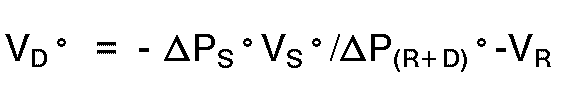
worinΔPS° = Änderung im Druck des Steuer- bzw. Regelgases in der Quellenkammer (12), die aus der Aktivierung des Pumpmittels (25) resultiert;VS° = Volumen der Quellenkammer (12);ΔP(R+D)° = Änderung im Druck des Steuer- bzw. Regelgases in der Reservoirkammer (11) (bis zur flexiblen Membrane), die aus der Aktivierung des Pumpmittels (25) resultiert;VR = bekanntes Volumen der Reservoirkammer (11);und worin das im Schritt (L) berechnete Volumen bestimmt wird durch die Beziehung:

worin:ΔV = Änderung im Volumen des Fluids in dem isolierten Bereich (15);ΔVD = Änderung im Volumen des Steuer- bzw. Regelgases in dem isolierten Bereich;und worin DVD bestimmt wird durch die folgende Beziehung:

worinPSi = Druck des Steuer- bzw. Regelgases in der Quellenkammer (12) vor dem Öffnen des Quellenventilmittels (24);VSi = Volumen des Steuer- bzw. Regelgases in der Quellenkammer (12) vor dem Öffnen des Quellenventilmittels (24);PS = Änderung im Druck in dem Steuer- bzw. Regelgas in der Quellenkammer (12), die aus dem Öffnen des Quellenventilmittels (24) resultiert. - Ein System nach Anspruch 12, worin das Steuer- bzw. Regelmittel ein Testen des Systems durch alternatives Berechnen des im Schritt (G) berechneten Volumens durch die folgende Beziehung vorsieht:

worinPScal° = die Änderung im Druck des Steuer- bzw. Regelgases in der Quellenkammer (12) bis zu der flexiblen Membrane (19), die aus dem Öffnen des Quellenventilmittels (24) resultiert;P(R+D)° = Änderung im Druck des Steuer- bzw. Regelgases in der Reservoirkammer (12) (bis zu der flexiblen Membrane (19)), die aus der Aktivierung des Pumpmittels (25) resultiert;VS° = Volumen der Quellenkammer (12).
Applications Claiming Priority (2)
| Application Number | Priority Date | Filing Date | Title |
|---|---|---|---|
| US07/092,481 US4826482A (en) | 1986-03-04 | 1987-09-03 | Enhanced pressure measurement flow control system |
| US92481 | 1987-09-03 |
Publications (3)
| Publication Number | Publication Date |
|---|---|
| EP0332690A1 EP0332690A1 (de) | 1989-09-20 |
| EP0332690A4 EP0332690A4 (en) | 1990-09-26 |
| EP0332690B1 true EP0332690B1 (de) | 1993-08-04 |
Family
ID=22233431
Family Applications (1)
| Application Number | Title | Priority Date | Filing Date |
|---|---|---|---|
| EP88908607A Expired - Lifetime EP0332690B1 (de) | 1987-09-03 | 1988-09-01 | Verbesserter flussmeter mit druckmessung |
Country Status (6)
| Country | Link |
|---|---|
| US (1) | US4826482A (de) |
| EP (1) | EP0332690B1 (de) |
| JP (1) | JP3092070B2 (de) |
| CA (1) | CA1290211C (de) |
| DE (1) | DE3882966T2 (de) |
| WO (1) | WO1989001795A1 (de) |
Cited By (2)
| Publication number | Priority date | Publication date | Assignee | Title |
|---|---|---|---|---|
| WO2005009512A1 (en) | 2003-07-31 | 2005-02-03 | Debiotech S.A. | A system for performing fluid administration |
| WO2005009511A2 (en) | 2003-07-31 | 2005-02-03 | Debiotech S.A. | A system for performing peritoneal dialysis |
Families Citing this family (176)
| Publication number | Priority date | Publication date | Assignee | Title |
|---|---|---|---|---|
| US5349852A (en) * | 1986-03-04 | 1994-09-27 | Deka Products Limited Partnership | Pump controller using acoustic spectral analysis |
| US5088515A (en) * | 1989-05-01 | 1992-02-18 | Kamen Dean L | Valve system with removable fluid interface |
| US5575310A (en) * | 1986-03-04 | 1996-11-19 | Deka Products Limited Partnership | Flow control system with volume-measuring system using a resonatable mass |
| US4976162A (en) * | 1987-09-03 | 1990-12-11 | Kamen Dean L | Enhanced pressure measurement flow control system |
| DE3805368C1 (de) * | 1988-02-17 | 1989-08-24 | Peter P. Dipl.-Ing. Wiest | |
| US5026348A (en) * | 1988-06-06 | 1991-06-25 | The General Hospital Corporation | Apparatus and method for the detection of IV catheter obstruction and extravasation |
| US5205819A (en) * | 1989-05-11 | 1993-04-27 | Bespak Plc | Pump apparatus for biomedical use |
| US4984457A (en) * | 1989-08-18 | 1991-01-15 | The United States Of America As Represented By The Administrator Of The National Aeronautics And Space Administration | Tank gauging apparatus and method |
| FI88343C (fi) * | 1989-12-28 | 1993-04-26 | Antti Johannes Niemi | Foerfarande och anordning foer beaktande av varierande volym och floede vid reglering av genomstroemningsprocesser |
| US5185084A (en) * | 1990-03-02 | 1993-02-09 | Cytyc Corporation | Method and apparatus for control of flow through a filter chamber by measured chamber equilibration pressure |
| FR2672218B1 (fr) * | 1991-02-06 | 1998-04-24 | Hospal Ind | Dispositif et procede de mise a niveau d'un liquide dans une chambre d'un circuit extracorporel de sang. |
| DE4121185A1 (de) * | 1991-03-11 | 1993-01-07 | Pierburg Gmbh | Vorrichtung zum messen des anteils fluessigen brennstoffs in einem tank |
| US5755683A (en) * | 1995-06-07 | 1998-05-26 | Deka Products Limited Partnership | Stopcock valve |
| US5713865A (en) * | 1991-11-15 | 1998-02-03 | Deka Products Limited Partnership | Intravenous-line air-elimination system |
| US5560247A (en) * | 1992-09-16 | 1996-10-01 | Honda Giken Kogyo Kabushiki Kaisha | Exhaust gas sampling device for outboard motor |
| EP0847769B1 (de) * | 1993-03-03 | 2001-08-29 | Deka Products Limited Partnership | Kassette für Periotonealdialyse |
| US5474683A (en) * | 1993-03-03 | 1995-12-12 | Deka Products Limited Partnership | Peritoneal dialysis systems and methods employing pneumatic pressure and temperature-corrected liquid volume measurements |
| US5438510A (en) * | 1993-03-03 | 1995-08-01 | Deka Products Limited Partnership | User interface and monitoring functions for automated peritoneal dialysis systems |
| US5324422A (en) * | 1993-03-03 | 1994-06-28 | Baxter International Inc. | User interface for automated peritoneal dialysis systems |
| US5431626A (en) * | 1993-03-03 | 1995-07-11 | Deka Products Limited Partnership | Liquid pumping mechanisms for peritoneal dialysis systems employing fluid pressure |
| US5350357A (en) * | 1993-03-03 | 1994-09-27 | Deka Products Limited Partnership | Peritoneal dialysis systems employing a liquid distribution and pumping cassette that emulates gravity flow |
| US5328382A (en) * | 1993-04-13 | 1994-07-12 | Molex Incorporated | Electrical connector with external seal and internal terminal retaining means |
| US5507737A (en) * | 1993-04-22 | 1996-04-16 | Siemens Elema Ab | Apparatus for determining the volume of a bellows reservoir for medication in an implantable infusion system |
| SE9301344D0 (sv) * | 1993-04-22 | 1993-04-22 | Siemens-Elema Ab | Foerfarande och anordning foer att bestaemma volymen hos en baelgbehaallare foer medikament vid ett implanterbart infusionssystem |
| US5421208A (en) * | 1994-05-19 | 1995-06-06 | Baxter International Inc. | Instantaneous volume measurement system and method for non-invasively measuring liquid parameters |
| US5624409A (en) * | 1994-06-10 | 1997-04-29 | Fluidsense Corporation | Variable-pulse dynamic fluid flow controller |
| US5640995A (en) * | 1995-03-14 | 1997-06-24 | Baxter International Inc. | Electrofluidic standard module and custom circuit board assembly |
| US5520638A (en) * | 1995-03-28 | 1996-05-28 | Arthrex, Inc. | Main pump tubing for arthroscopy infusion pump |
| US6070761A (en) * | 1997-08-22 | 2000-06-06 | Deka Products Limited Partnership | Vial loading method and apparatus for intelligent admixture and delivery of intravenous drugs |
| GB9724223D0 (en) * | 1997-11-18 | 1998-01-14 | Pa Consulting Services | Drug delivery device |
| US6041801A (en) | 1998-07-01 | 2000-03-28 | Deka Products Limited Partnership | System and method for measuring when fluid has stopped flowing within a line |
| US6666665B1 (en) | 1999-03-04 | 2003-12-23 | Baxter International Inc. | Fluid delivery mechanism having a plurality of plungers for compressing a metering chamber |
| US6905479B1 (en) | 1999-07-20 | 2005-06-14 | Deka Products Limited Partnership | Pumping cartridge having an integrated filter and method for filtering a fluid with the cartridge |
| US6302653B1 (en) * | 1999-07-20 | 2001-10-16 | Deka Products Limited Partnership | Methods and systems for detecting the presence of a gas in a pump and preventing a gas from being pumped from a pump |
| US6416293B1 (en) | 1999-07-20 | 2002-07-09 | Deka Products Limited Partnership | Pumping cartridge including a bypass valve and method for directing flow in a pumping cartridge |
| US6877713B1 (en) | 1999-07-20 | 2005-04-12 | Deka Products Limited Partnership | Tube occluder and method for occluding collapsible tubes |
| US6382923B1 (en) * | 1999-07-20 | 2002-05-07 | Deka Products Ltd. Partnership | Pump chamber having at least one spacer for inhibiting the pumping of a gas |
| US6604908B1 (en) | 1999-07-20 | 2003-08-12 | Deka Products Limited Partnership | Methods and systems for pulsed delivery of fluids from a pump |
| US8722422B2 (en) | 1999-09-03 | 2014-05-13 | Therakos, Inc. | Uninterrupted flow pump apparatus and method |
| US6495366B1 (en) | 1999-09-03 | 2002-12-17 | Therakos, Inc. | Uninterrupted flow pump apparatus and method |
| US6497676B1 (en) | 2000-02-10 | 2002-12-24 | Baxter International | Method and apparatus for monitoring and controlling peritoneal dialysis therapy |
| US6793643B1 (en) | 2000-04-21 | 2004-09-21 | Therakos, Inc. | Low extracorporeal volume treatment system |
| US6503062B1 (en) | 2000-07-10 | 2003-01-07 | Deka Products Limited Partnership | Method for regulating fluid pump pressure |
| US6905314B2 (en) | 2001-10-16 | 2005-06-14 | Baxter International Inc. | Pump having flexible liner and compounding apparatus having such a pump |
| US6769231B2 (en) | 2001-07-19 | 2004-08-03 | Baxter International, Inc. | Apparatus, method and flexible bag for use in manufacturing |
| US20030017066A1 (en) * | 2001-07-19 | 2003-01-23 | Baxter International Inc. | Apparatus, flexible bag and method for dispensing |
| US20030125662A1 (en) | 2002-01-03 | 2003-07-03 | Tuan Bui | Method and apparatus for providing medical treatment therapy based on calculated demand |
| US20080172026A1 (en) | 2006-10-17 | 2008-07-17 | Blomquist Michael L | Insulin pump having a suspension bolus |
| AU2003230862A1 (en) | 2002-04-11 | 2003-10-27 | Deka Products Limited Partnership | System and method for delivering a target volume of fluid |
| US6939111B2 (en) * | 2002-05-24 | 2005-09-06 | Baxter International Inc. | Method and apparatus for controlling medical fluid pressure |
| US7153286B2 (en) | 2002-05-24 | 2006-12-26 | Baxter International Inc. | Automated dialysis system |
| US7175606B2 (en) | 2002-05-24 | 2007-02-13 | Baxter International Inc. | Disposable medical fluid unit having rigid frame |
| DE10224750A1 (de) | 2002-06-04 | 2003-12-24 | Fresenius Medical Care De Gmbh | Vorrichtung zur Behandlung einer medizinischen Flüssigkeit |
| US7238164B2 (en) | 2002-07-19 | 2007-07-03 | Baxter International Inc. | Systems, methods and apparatuses for pumping cassette-based therapies |
| AU2003274901A1 (en) | 2002-07-19 | 2004-02-09 | Baxter Healthcare S.A. | Systems and methods for performing peritoneal dialysis |
| US7008403B1 (en) * | 2002-07-19 | 2006-03-07 | Cognitive Ventures Corporation | Infusion pump and method for use |
| US7007824B2 (en) * | 2003-01-24 | 2006-03-07 | Baxter International Inc. | Liquid dispenser and flexible bag therefor |
| US20040144799A1 (en) * | 2003-01-24 | 2004-07-29 | Baxter International Inc. | Liquid dispenser and flexible bag therefor |
| EP1617888B1 (de) | 2003-04-23 | 2019-06-12 | Valeritas, Inc. | Hydraulisch aktivierte pumpe für langzeitabgabe von medikamenten |
| US20050011908A1 (en) * | 2003-07-16 | 2005-01-20 | Baxter International, Inc. | Dispenser and pressure/vacuum converting machine |
| JP4691503B2 (ja) * | 2003-10-28 | 2011-06-01 | バクスター・インターナショナル・インコーポレイテッド | 医療用流体システムのための、改善されたプライミング、一体性および水頭高さの方法および装置 |
| US7662139B2 (en) * | 2003-10-30 | 2010-02-16 | Deka Products Limited Partnership | Pump cassette with spiking assembly |
| US7354190B2 (en) * | 2003-10-30 | 2008-04-08 | Deka Products Limited Partnership | Two-stage mixing system, apparatus, and method |
| US8158102B2 (en) * | 2003-10-30 | 2012-04-17 | Deka Products Limited Partnership | System, device, and method for mixing a substance with a liquid |
| US8029454B2 (en) | 2003-11-05 | 2011-10-04 | Baxter International Inc. | High convection home hemodialysis/hemofiltration and sorbent system |
| US7776006B2 (en) | 2003-11-05 | 2010-08-17 | Baxter International Inc. | Medical fluid pumping system having real time volume determination |
| WO2006014425A1 (en) | 2004-07-02 | 2006-02-09 | Biovalve Technologies, Inc. | Methods and devices for delivering glp-1 and uses thereof |
| JP4722654B2 (ja) * | 2004-12-20 | 2011-07-13 | ルネサスエレクトロニクス株式会社 | オシレータ及びこれを用いたチャージポンプ回路 |
| US7935074B2 (en) | 2005-02-28 | 2011-05-03 | Fresenius Medical Care Holdings, Inc. | Cassette system for peritoneal dialysis machine |
| US20060195064A1 (en) * | 2005-02-28 | 2006-08-31 | Fresenius Medical Care Holdings, Inc. | Portable apparatus for peritoneal dialysis therapy |
| US20060276748A1 (en) * | 2005-05-17 | 2006-12-07 | Infussafe Llc | Infusion monitoring device system and method |
| US8197231B2 (en) | 2005-07-13 | 2012-06-12 | Purity Solutions Llc | Diaphragm pump and related methods |
| US20080092969A1 (en) * | 2006-08-07 | 2008-04-24 | Diperna Paul Mario | Variable flow reshapable flow restrictor apparatus and related methods |
| US10010686B2 (en) | 2006-02-27 | 2018-07-03 | Ivenix, Inc. | Fluid control system and disposable assembly |
| WO2007106232A2 (en) * | 2006-02-27 | 2007-09-20 | Fluidnet Corporation | Volume measurement using gas laws |
| US9146564B2 (en) | 2006-03-06 | 2015-09-29 | Deka Products Limited Partnership | Product dispensing system |
| WO2007110825A2 (en) * | 2006-03-29 | 2007-10-04 | Koninklijke Philips Electronics N.V. | Fluid processing and volume determination system |
| KR101361376B1 (ko) | 2006-03-30 | 2014-02-10 | 발레리타스 인코포레이티드 | 복합-카트리지 유체 전달 장치 |
| US10537671B2 (en) | 2006-04-14 | 2020-01-21 | Deka Products Limited Partnership | Automated control mechanisms in a hemodialysis apparatus |
| EP2724736B1 (de) | 2006-04-14 | 2022-06-08 | DEKA Products Limited Partnership | Kassette mit eingehauster pumpe |
| US8926550B2 (en) * | 2006-08-31 | 2015-01-06 | Fresenius Medical Care Holdings, Inc. | Data communication system for peritoneal dialysis machine |
| US8870811B2 (en) * | 2006-08-31 | 2014-10-28 | Fresenius Medical Care Holdings, Inc. | Peritoneal dialysis systems and related methods |
| US7998115B2 (en) | 2007-02-15 | 2011-08-16 | Baxter International Inc. | Dialysis system having optical flowrate detection |
| US7731689B2 (en) | 2007-02-15 | 2010-06-08 | Baxter International Inc. | Dialysis system having inductive heating |
| US8558964B2 (en) | 2007-02-15 | 2013-10-15 | Baxter International Inc. | Dialysis system having display with electromagnetic compliance (“EMC”) seal |
| US8870812B2 (en) | 2007-02-15 | 2014-10-28 | Baxter International Inc. | Dialysis system having video display with ambient light adjustment |
| US8361023B2 (en) | 2007-02-15 | 2013-01-29 | Baxter International Inc. | Dialysis system with efficient battery back-up |
| US8425471B2 (en) | 2007-02-27 | 2013-04-23 | Deka Products Limited Partnership | Reagent supply for a hemodialysis system |
| US8562834B2 (en) | 2007-02-27 | 2013-10-22 | Deka Products Limited Partnership | Modular assembly for a portable hemodialysis system |
| US8409441B2 (en) | 2007-02-27 | 2013-04-02 | Deka Products Limited Partnership | Blood treatment systems and methods |
| US20090107335A1 (en) | 2007-02-27 | 2009-04-30 | Deka Products Limited Partnership | Air trap for a medical infusion device |
| US8888470B2 (en) | 2007-02-27 | 2014-11-18 | Deka Products Limited Partnership | Pumping cassette |
| US8393690B2 (en) | 2007-02-27 | 2013-03-12 | Deka Products Limited Partnership | Enclosure for a portable hemodialysis system |
| US8042563B2 (en) | 2007-02-27 | 2011-10-25 | Deka Products Limited Partnership | Cassette system integrated apparatus |
| US8491184B2 (en) | 2007-02-27 | 2013-07-23 | Deka Products Limited Partnership | Sensor apparatus systems, devices and methods |
| KR101861192B1 (ko) | 2007-02-27 | 2018-05-28 | 데카 프로덕츠 리미티드 파트너쉽 | 혈액투석 장치 및 방법 |
| US9028691B2 (en) | 2007-02-27 | 2015-05-12 | Deka Products Limited Partnership | Blood circuit assembly for a hemodialysis system |
| US8357298B2 (en) | 2007-02-27 | 2013-01-22 | Deka Products Limited Partnership | Hemodialysis systems and methods |
| AU2008260230B2 (en) * | 2007-05-29 | 2013-09-19 | Fresenius Medical Care Holdings, Inc. | Solutions, dialysates, and related methods |
| US7909795B2 (en) * | 2007-07-05 | 2011-03-22 | Baxter International Inc. | Dialysis system having disposable cassette and interface therefore |
| US7957927B2 (en) * | 2007-07-05 | 2011-06-07 | Baxter International Inc. | Temperature compensation for pneumatic pumping system |
| US8715235B2 (en) * | 2007-07-05 | 2014-05-06 | Baxter International Inc. | Dialysis system having disposable cassette and heated cassette interface |
| US9270010B2 (en) | 2007-09-06 | 2016-02-23 | Deka Products Limited Partnership | RFID system with an eddy current trap |
| US7892197B2 (en) * | 2007-09-19 | 2011-02-22 | Fresenius Medical Care Holdings, Inc. | Automatic prime of an extracorporeal blood circuit |
| US8771508B2 (en) | 2008-08-27 | 2014-07-08 | Deka Products Limited Partnership | Dialyzer cartridge mounting arrangement for a hemodialysis system |
| US8863772B2 (en) * | 2008-08-27 | 2014-10-21 | Deka Products Limited Partnership | Occluder for a medical infusion system |
| US7905853B2 (en) | 2007-10-30 | 2011-03-15 | Baxter International Inc. | Dialysis system having integrated pneumatic manifold |
| US11738130B2 (en) | 2008-01-23 | 2023-08-29 | Deka Products Limited Partnership | Fluid line autoconnect apparatus and methods for medical treatment system |
| US10201647B2 (en) | 2008-01-23 | 2019-02-12 | Deka Products Limited Partnership | Medical treatment system and methods using a plurality of fluid lines |
| MX340210B (es) | 2008-01-23 | 2016-06-29 | Deka Products Ltd Partnership * | Componentes desechables para sistemas y métodos de autoconexión de una linea de fluido. |
| US8986253B2 (en) | 2008-01-25 | 2015-03-24 | Tandem Diabetes Care, Inc. | Two chamber pumps and related methods |
| US20090191067A1 (en) * | 2008-01-25 | 2009-07-30 | Phluid,Inc. | Two chamber pumps and related methods |
| US8062513B2 (en) | 2008-07-09 | 2011-11-22 | Baxter International Inc. | Dialysis system and machine having therapy prescription recall |
| US9514283B2 (en) | 2008-07-09 | 2016-12-06 | Baxter International Inc. | Dialysis system having inventory management including online dextrose mixing |
| US8056582B2 (en) * | 2008-08-08 | 2011-11-15 | Tandem Diabetes Care, Inc. | System of stepped flow rate regulation using compressible members |
| US8359877B2 (en) | 2008-08-15 | 2013-01-29 | Deka Products Limited Partnership | Water vending apparatus |
| MX2011002251A (es) | 2008-08-27 | 2011-05-19 | Deka Products Lp | Arquitectura de control y metodos para sistemas de tratamiento de la sangre. |
| US8408421B2 (en) | 2008-09-16 | 2013-04-02 | Tandem Diabetes Care, Inc. | Flow regulating stopcocks and related methods |
| CA2737461A1 (en) | 2008-09-19 | 2010-03-25 | Tandem Diabetes Care, Inc. | Solute concentration measurement device and related methods |
| US8192401B2 (en) | 2009-03-20 | 2012-06-05 | Fresenius Medical Care Holdings, Inc. | Medical fluid pump systems and related components and methods |
| WO2011008858A1 (en) | 2009-07-15 | 2011-01-20 | Fresenius Medical Care Holdings, Inc. | Medical fluid cassettes and related systems and methods |
| US8926561B2 (en) | 2009-07-30 | 2015-01-06 | Tandem Diabetes Care, Inc. | Infusion pump system with disposable cartridge having pressure venting and pressure feedback |
| US8720913B2 (en) | 2009-08-11 | 2014-05-13 | Fresenius Medical Care Holdings, Inc. | Portable peritoneal dialysis carts and related systems |
| US9207143B2 (en) * | 2009-08-18 | 2015-12-08 | Innovative Pressure Testing, Llc | System and method for determining leaks in a complex system |
| US10031042B2 (en) | 2009-08-18 | 2018-07-24 | Innovative Pressure Testing, Llc | System and method for detecting leaks |
| WO2011053810A2 (en) | 2009-10-30 | 2011-05-05 | Deka Products Limited Partnership | Apparatus and method for detecting disconnection of an intravascular access device |
| CN105251072B (zh) * | 2009-12-24 | 2017-08-25 | 昆山韦睿医疗科技有限公司 | 一种透析系统 |
| WO2013096909A2 (en) | 2011-12-21 | 2013-06-27 | Deka Products Limited Partnership | System, method, and apparatus for infusing fluid |
| DE102010053973A1 (de) | 2010-12-09 | 2012-06-14 | Fresenius Medical Care Deutschland Gmbh | Medizinisches Gerät mit einer Heizung |
| EP2654825B1 (de) | 2010-12-20 | 2017-08-02 | Fresenius Medical Care Holdings, Inc. | Medizinische flüssigkeitskassetten sowie entsprechende systeme und verfahren |
| US8382711B2 (en) * | 2010-12-29 | 2013-02-26 | Baxter International Inc. | Intravenous pumping air management systems and methods |
| US9624915B2 (en) | 2011-03-09 | 2017-04-18 | Fresenius Medical Care Holdings, Inc. | Medical fluid delivery sets and related systems and methods |
| AU2012254069B2 (en) | 2011-04-21 | 2015-10-08 | Fresenius Medical Care Holdings, Inc. | Medical fluid pumping systems and related devices and methods |
| SG10201809897VA (en) | 2011-05-24 | 2018-12-28 | Deka Products Lp | Hemodialysis System |
| MX344664B (es) | 2011-05-24 | 2017-01-04 | Deka Products Lp | Sistemas y metodos de tratamiento de la sangre. |
| DE102011106113B4 (de) * | 2011-06-09 | 2013-11-21 | Fresenius Medical Care Deutschland Gmbh | Verfahren und Vorrichtung zum Überprüfen der Förderleistung mindestens eines ersten und eines zweiten Fördermittels einer Vorrichtung zur extrakorporalen Blutbehandlung |
| MX352606B (es) | 2011-10-28 | 2017-11-29 | Deka Products Lp | Sistema de dosificacion de producto con bomba de solenoide controlada por modulacion por anchura de impulsos. |
| US9186449B2 (en) | 2011-11-01 | 2015-11-17 | Fresenius Medical Care Holdings, Inc. | Dialysis machine support assemblies and related systems and methods |
| US12303631B2 (en) | 2011-11-04 | 2025-05-20 | Deka Products Limited Partnership | Medical treatment system and methods using a plurality of fluid lines |
| US9180242B2 (en) | 2012-05-17 | 2015-11-10 | Tandem Diabetes Care, Inc. | Methods and devices for multiple fluid transfer |
| US9364655B2 (en) | 2012-05-24 | 2016-06-14 | Deka Products Limited Partnership | Flexible tubing occlusion assembly |
| CN104507516B (zh) | 2012-05-24 | 2018-02-16 | 德卡产品有限公司 | 用于输注流体的装置 |
| US9555186B2 (en) | 2012-06-05 | 2017-01-31 | Tandem Diabetes Care, Inc. | Infusion pump system with disposable cartridge having pressure venting and pressure feedback |
| US9610392B2 (en) | 2012-06-08 | 2017-04-04 | Fresenius Medical Care Holdings, Inc. | Medical fluid cassettes and related systems and methods |
| US9500188B2 (en) | 2012-06-11 | 2016-11-22 | Fresenius Medical Care Holdings, Inc. | Medical fluid cassettes and related systems and methods |
| CN105143094B (zh) | 2013-03-14 | 2019-06-14 | 德卡产品有限公司 | 产品配制系统 |
| US9561323B2 (en) | 2013-03-14 | 2017-02-07 | Fresenius Medical Care Holdings, Inc. | Medical fluid cassette leak detection methods and devices |
| US9173998B2 (en) | 2013-03-14 | 2015-11-03 | Tandem Diabetes Care, Inc. | System and method for detecting occlusions in an infusion pump |
| US9713664B2 (en) | 2013-03-15 | 2017-07-25 | Fresenius Medical Care Holdings, Inc. | Nuclear magnetic resonance module for a dialysis machine |
| US9433718B2 (en) | 2013-03-15 | 2016-09-06 | Fresenius Medical Care Holdings, Inc. | Medical fluid system including radio frequency (RF) device within a magnetic assembly, and fluid cartridge body with one of multiple passageways disposed within the RF device, and specially configured cartridge gap accepting a portion of said RF device |
| JP6456911B2 (ja) | 2013-03-15 | 2019-01-23 | デカ・プロダクツ・リミテッド・パートナーシップ | 血液処置システムおよび方法 |
| US9180243B2 (en) | 2013-03-15 | 2015-11-10 | Tandem Diabetes Care, Inc. | Detection of infusion pump conditions |
| US9566377B2 (en) | 2013-03-15 | 2017-02-14 | Fresenius Medical Care Holdings, Inc. | Medical fluid sensing and concentration determination in a fluid cartridge with multiple passageways, using a radio frequency device situated within a magnetic field |
| US9772386B2 (en) | 2013-03-15 | 2017-09-26 | Fresenius Medical Care Holdings, Inc. | Dialysis system with sample concentration determination device using magnet and radio frequency coil assemblies |
| US9597439B2 (en) | 2013-03-15 | 2017-03-21 | Fresenius Medical Care Holdings, Inc. | Medical fluid sensing and concentration determination using radio frequency energy and a magnetic field |
| US10117985B2 (en) | 2013-08-21 | 2018-11-06 | Fresenius Medical Care Holdings, Inc. | Determining a volume of medical fluid pumped into or out of a medical fluid cassette |
| EP3058328B1 (de) | 2013-10-17 | 2020-04-29 | Innovative Pressure Testing LLC | System und verfahren für benchmark-druckprüfung |
| CA2926288C (en) | 2013-10-17 | 2020-04-14 | Innovative Pressure Testing, Llc | System and method for a benchmark pressure test |
| US10286135B2 (en) | 2014-03-28 | 2019-05-14 | Fresenius Medical Care Holdings, Inc. | Measuring conductivity of a medical fluid |
| EP4316547A3 (de) | 2014-05-27 | 2024-05-08 | DEKA Products Limited Partnership | Systeme und verfahren zur erkennung einer gefässzugangstrennung |
| EP3148607B1 (de) | 2014-05-27 | 2019-07-10 | DEKA Products Limited Partnership | Steuerungssysteme für medizinische blut- oder fluidhandhabungsvorrichtungen |
| EP4714477A2 (de) | 2014-06-05 | 2026-03-25 | DEKA Products Limited Partnership | Medizinisches behandlungssystem und verfahren mit mehreren flüssigkeitsleitungen |
| EP3359641B1 (de) | 2015-10-09 | 2020-01-08 | DEKA Products Limited Partnership | Fluidume und bioreaktorsystem |
| EP3165881A1 (de) * | 2015-11-04 | 2017-05-10 | ETH Zurich | Verfahren, vorrichtung und system zur schätzung eines flüssigkeitsvolumens und geeigneter gasdruck in einem membranausdehnungsgefäss |
| US11299705B2 (en) | 2016-11-07 | 2022-04-12 | Deka Products Limited Partnership | System and method for creating tissue |
| GB2561898A (en) * | 2017-04-28 | 2018-10-31 | Mexichem Fluor Sa De Cv | Improvements in or relating to propellant conditioning assemblies |
| US11135345B2 (en) | 2017-05-10 | 2021-10-05 | Fresenius Medical Care Holdings, Inc. | On demand dialysate mixing using concentrates |
| US11179516B2 (en) | 2017-06-22 | 2021-11-23 | Baxter International Inc. | Systems and methods for incorporating patient pressure into medical fluid delivery |
| CN109724667B (zh) * | 2017-10-30 | 2022-08-05 | 诺信公司 | 容器内液体体积百分比的检测方法和系统以及具有该系统的分配器 |
| SG11202009657YA (en) | 2018-04-17 | 2020-10-29 | Deka Products Lp | Peritoneal dialysis cassette with pneumatic pump |
| US11504458B2 (en) | 2018-10-17 | 2022-11-22 | Fresenius Medical Care Holdings, Inc. | Ultrasonic authentication for dialysis |
| AU2019404039B2 (en) | 2018-12-19 | 2022-07-07 | Boston Scientific Scimed, Inc. | Dampening element for fluid management system |
| CA3123018C (en) | 2019-03-19 | 2024-05-14 | Deka Products Limited Partnership | Volumetric standard cassettes |
| US12054924B2 (en) | 2020-05-28 | 2024-08-06 | Zurn Water, Llc | Smart and connected backflow preventer assembly |
| WO2022225820A1 (en) | 2021-04-19 | 2022-10-27 | Baxter International Inc. | Peritoneal dialysis system using ideal gas law |
| US20230039808A1 (en) * | 2021-08-07 | 2023-02-09 | Johnson & Johnson Surgical Vision, Inc. | Electronically detecting phacoemulsification tip engagement with a lens |
Family Cites Families (7)
| Publication number | Priority date | Publication date | Assignee | Title |
|---|---|---|---|---|
| US2116636A (en) * | 1936-02-18 | 1938-05-10 | Neumann Georg | Device for indicating the amount of material in a tank |
| US2747400A (en) * | 1952-05-06 | 1956-05-29 | Fatio Paul | Apparatus for volumetric measurements |
| US4204538A (en) * | 1978-06-07 | 1980-05-27 | Imed Corporation | Cassette for intravenous controller |
| US4237881A (en) * | 1978-12-26 | 1980-12-09 | Anatros Corporation | Device for the intravenous or enteric infusion of liquids into the human body at a predetermined constant rate |
| US4505701A (en) * | 1982-05-17 | 1985-03-19 | Navato Jose R | Automatic parenteral infusion apparatus |
| US4486190A (en) * | 1982-12-27 | 1984-12-04 | Consolidated Controls Corporation | Precision medication dispensing system and method |
| DE3408331C2 (de) * | 1984-03-07 | 1986-06-12 | Fresenius AG, 6380 Bad Homburg | Pumpanordnung für medizinische Zwecke |
-
1987
- 1987-09-03 US US07/092,481 patent/US4826482A/en not_active Expired - Lifetime
-
1988
- 1988-09-01 EP EP88908607A patent/EP0332690B1/de not_active Expired - Lifetime
- 1988-09-01 JP JP63507766A patent/JP3092070B2/ja not_active Expired - Lifetime
- 1988-09-01 DE DE88908607T patent/DE3882966T2/de not_active Expired - Lifetime
- 1988-09-01 WO PCT/US1988/003079 patent/WO1989001795A1/en not_active Ceased
- 1988-09-06 CA CA000576571A patent/CA1290211C/en not_active Expired - Lifetime
Cited By (2)
| Publication number | Priority date | Publication date | Assignee | Title |
|---|---|---|---|---|
| WO2005009512A1 (en) | 2003-07-31 | 2005-02-03 | Debiotech S.A. | A system for performing fluid administration |
| WO2005009511A2 (en) | 2003-07-31 | 2005-02-03 | Debiotech S.A. | A system for performing peritoneal dialysis |
Also Published As
| Publication number | Publication date |
|---|---|
| JP3092070B2 (ja) | 2000-09-25 |
| EP0332690A4 (en) | 1990-09-26 |
| CA1290211C (en) | 1991-10-08 |
| DE3882966D1 (de) | 1993-09-09 |
| EP0332690A1 (de) | 1989-09-20 |
| JPH02501198A (ja) | 1990-04-26 |
| WO1989001795A1 (en) | 1989-03-09 |
| DE3882966T2 (de) | 1993-11-25 |
| US4826482A (en) | 1989-05-02 |
Similar Documents
| Publication | Publication Date | Title |
|---|---|---|
| EP0332690B1 (de) | Verbesserter flussmeter mit druckmessung | |
| US8986253B2 (en) | Two chamber pumps and related methods | |
| US5193990A (en) | Fluid management system with auxiliary dispensing chamber | |
| US7255680B1 (en) | Positive pressure infusion system having downstream resistance measurement capability | |
| EP0262182B1 (de) | Durchflussregelsystem mittels druckmessung | |
| US20070264130A1 (en) | Infusion Pumps and Methods for Use | |
| EP1131559B1 (de) | Methode und einrichtung zur dichtigkeitsprüfung einer membranpumpe | |
| AU609804B2 (en) | Pressure sensor assembly for disposable pump cassette | |
| US8408421B2 (en) | Flow regulating stopcocks and related methods | |
| EP0471000B1 (de) | Verbessertes debitregelungssystem durch druckmessung | |
| US20090191067A1 (en) | Two chamber pumps and related methods | |
| CN111902786B (zh) | 具有绝对压力和差压换能器的质量流量控制器 | |
| US4790194A (en) | Flow measurement device | |
| US20090131863A1 (en) | Volume Measurement Using Gas Laws | |
| EP0670476B1 (de) | Flüssigkeitsdetektor | |
| GB2373054A (en) | Computer program for performing a method calibrating and correcting mass flow measurement in real time | |
| JP7815587B2 (ja) | マイクロ流体液体送出装置 | |
| JPS586504B2 (ja) | 限外濾過量測定装置 | |
| HK1119982B (en) | Positive pressure infusion system having downstream resistance measurement capability | |
| HK1151997A (en) | Positive pressure infusion system having downstream resistance measurement capability |
Legal Events
| Date | Code | Title | Description |
|---|---|---|---|
| PUAI | Public reference made under article 153(3) epc to a published international application that has entered the european phase |
Free format text: ORIGINAL CODE: 0009012 |
|
| 17P | Request for examination filed |
Effective date: 19890526 |
|
| AK | Designated contracting states |
Kind code of ref document: A1 Designated state(s): BE CH DE FR GB IT LI NL SE |
|
| A4 | Supplementary search report drawn up and despatched |
Effective date: 19900809 |
|
| AK | Designated contracting states |
Kind code of ref document: A4 Designated state(s): BE CH DE FR GB IT LI NL SE |
|
| RAP1 | Party data changed (applicant data changed or rights of an application transferred) |
Owner name: DEKA PRODUCTS LIMITED PARTNERSHIP |
|
| RIN1 | Information on inventor provided before grant (corrected) |
Inventor name: KAMEN, DEAN L. |
|
| 17Q | First examination report despatched |
Effective date: 19920818 |
|
| GRAA | (expected) grant |
Free format text: ORIGINAL CODE: 0009210 |
|
| AK | Designated contracting states |
Kind code of ref document: B1 Designated state(s): BE CH DE FR GB IT LI NL SE |
|
| ITF | It: translation for a ep patent filed | ||
| REF | Corresponds to: |
Ref document number: 3882966 Country of ref document: DE Date of ref document: 19930909 |
|
| ET | Fr: translation filed | ||
| PLBE | No opposition filed within time limit |
Free format text: ORIGINAL CODE: 0009261 |
|
| STAA | Information on the status of an ep patent application or granted ep patent |
Free format text: STATUS: NO OPPOSITION FILED WITHIN TIME LIMIT |
|
| 26N | No opposition filed | ||
| EAL | Se: european patent in force in sweden |
Ref document number: 88908607.0 |
|
| REG | Reference to a national code |
Ref country code: GB Ref legal event code: IF02 |
|
| PGFP | Annual fee paid to national office [announced via postgrant information from national office to epo] |
Ref country code: CH Payment date: 20070924 Year of fee payment: 20 |
|
| PGFP | Annual fee paid to national office [announced via postgrant information from national office to epo] |
Ref country code: GB Payment date: 20070926 Year of fee payment: 20 |
|
| PGFP | Annual fee paid to national office [announced via postgrant information from national office to epo] |
Ref country code: IT Payment date: 20070927 Year of fee payment: 20 Ref country code: DE Payment date: 20071031 Year of fee payment: 20 Ref country code: NL Payment date: 20070923 Year of fee payment: 20 |
|
| PGFP | Annual fee paid to national office [announced via postgrant information from national office to epo] |
Ref country code: BE Payment date: 20071025 Year of fee payment: 20 Ref country code: SE Payment date: 20070926 Year of fee payment: 20 |
|
| PGFP | Annual fee paid to national office [announced via postgrant information from national office to epo] |
Ref country code: FR Payment date: 20070917 Year of fee payment: 20 |
|
| REG | Reference to a national code |
Ref country code: CH Ref legal event code: PL |
|
| REG | Reference to a national code |
Ref country code: GB Ref legal event code: PE20 Expiry date: 20080831 |
|
| BE20 | Be: patent expired |
Owner name: *DEKA PRODUCTS LTD PARTNERSHIP Effective date: 20080901 |
|
| NLV7 | Nl: ceased due to reaching the maximum lifetime of a patent |
Effective date: 20080901 |
|
| EUG | Se: european patent has lapsed | ||
| PG25 | Lapsed in a contracting state [announced via postgrant information from national office to epo] |
Ref country code: NL Free format text: LAPSE BECAUSE OF EXPIRATION OF PROTECTION Effective date: 20080901 |
|
| PG25 | Lapsed in a contracting state [announced via postgrant information from national office to epo] |
Ref country code: GB Free format text: LAPSE BECAUSE OF EXPIRATION OF PROTECTION Effective date: 20080831 |