EP0332725B1 - Mit beschränkter Sauerstoffdurchlässigkeit versehener Plastikverschluss mit angeklebter Abdichtungsverbindung und Verfahren zur Herstellung desselben - Google Patents
Mit beschränkter Sauerstoffdurchlässigkeit versehener Plastikverschluss mit angeklebter Abdichtungsverbindung und Verfahren zur Herstellung desselben Download PDFInfo
- Publication number
- EP0332725B1 EP0332725B1 EP19880104123 EP88104123A EP0332725B1 EP 0332725 B1 EP0332725 B1 EP 0332725B1 EP 19880104123 EP19880104123 EP 19880104123 EP 88104123 A EP88104123 A EP 88104123A EP 0332725 B1 EP0332725 B1 EP 0332725B1
- Authority
- EP
- European Patent Office
- Prior art keywords
- insert
- accordance
- closure
- metal foil
- layer
- Prior art date
- Legal status (The legal status is an assumption and is not a legal conclusion. Google has not performed a legal analysis and makes no representation as to the accuracy of the status listed.)
- Expired
Links
- 239000004033 plastic Substances 0.000 title claims description 14
- 229920003023 plastic Polymers 0.000 title claims description 14
- 238000000034 method Methods 0.000 title claims description 10
- 230000004888 barrier function Effects 0.000 title claims description 6
- 238000013023 gasketing Methods 0.000 title claims description 6
- 150000001875 compounds Chemical class 0.000 title claims description 5
- QVGXLLKOCUKJST-UHFFFAOYSA-N atomic oxygen Chemical compound [O] QVGXLLKOCUKJST-UHFFFAOYSA-N 0.000 title 1
- 229910052760 oxygen Inorganic materials 0.000 title 1
- 239000001301 oxygen Substances 0.000 title 1
- 239000011888 foil Substances 0.000 claims description 19
- 238000000576 coating method Methods 0.000 claims description 14
- 229910052751 metal Inorganic materials 0.000 claims description 14
- 239000002184 metal Substances 0.000 claims description 14
- 239000011248 coating agent Substances 0.000 claims description 11
- 238000002347 injection Methods 0.000 claims description 8
- 239000007924 injection Substances 0.000 claims description 8
- 229920001944 Plastisol Polymers 0.000 claims description 7
- 239000004999 plastisol Substances 0.000 claims description 7
- 239000002904 solvent Substances 0.000 claims description 7
- -1 polypropylene Polymers 0.000 claims description 6
- 239000004743 Polypropylene Substances 0.000 claims description 5
- 229920001155 polypropylene Polymers 0.000 claims description 5
- 229920002397 thermoplastic olefin Polymers 0.000 claims description 5
- 239000005008 organosol coating Substances 0.000 claims description 4
- 239000007787 solid Substances 0.000 claims description 4
- 229910052782 aluminium Inorganic materials 0.000 claims description 3
- XAGFODPZIPBFFR-UHFFFAOYSA-N aluminium Chemical compound [Al] XAGFODPZIPBFFR-UHFFFAOYSA-N 0.000 claims description 3
- 239000000463 material Substances 0.000 claims description 3
- BZHJMEDXRYGGRV-UHFFFAOYSA-N Vinyl chloride Chemical compound ClC=C BZHJMEDXRYGGRV-UHFFFAOYSA-N 0.000 claims description 2
- 229920001577 copolymer Polymers 0.000 claims description 2
- 239000006185 dispersion Substances 0.000 claims description 2
- ISWSIDIOOBJBQZ-UHFFFAOYSA-N phenol group Chemical group C1(=CC=CC=C1)O ISWSIDIOOBJBQZ-UHFFFAOYSA-N 0.000 claims description 2
- 229920001897 terpolymer Polymers 0.000 claims description 2
- 239000002987 primer (paints) Substances 0.000 claims 8
- 230000002093 peripheral effect Effects 0.000 claims 1
- 239000002131 composite material Substances 0.000 description 4
- 238000007756 gravure coating Methods 0.000 description 3
- 229920000098 polyolefin Polymers 0.000 description 3
- 229920005629 polypropylene homopolymer Polymers 0.000 description 3
- 238000010438 heat treatment Methods 0.000 description 2
- 238000001746 injection moulding Methods 0.000 description 2
- 239000004698 Polyethylene Substances 0.000 description 1
- 230000000694 effects Effects 0.000 description 1
- 238000001125 extrusion Methods 0.000 description 1
- 230000004927 fusion Effects 0.000 description 1
- 230000006698 induction Effects 0.000 description 1
- 238000003475 lamination Methods 0.000 description 1
- 239000007788 liquid Substances 0.000 description 1
- 230000007774 longterm Effects 0.000 description 1
- 239000002905 metal composite material Substances 0.000 description 1
- 238000009928 pasteurization Methods 0.000 description 1
- 229920000573 polyethylene Polymers 0.000 description 1
- 229920005606 polypropylene copolymer Polymers 0.000 description 1
- 239000000565 sealant Substances 0.000 description 1
Images
Classifications
-
- B—PERFORMING OPERATIONS; TRANSPORTING
- B65—CONVEYING; PACKING; STORING; HANDLING THIN OR FILAMENTARY MATERIAL
- B65D—CONTAINERS FOR STORAGE OR TRANSPORT OF ARTICLES OR MATERIALS, e.g. BAGS, BARRELS, BOTTLES, BOXES, CANS, CARTONS, CRATES, DRUMS, JARS, TANKS, HOPPERS, FORWARDING CONTAINERS; ACCESSORIES, CLOSURES, OR FITTINGS THEREFOR; PACKAGING ELEMENTS; PACKAGES
- B65D41/00—Caps, e.g. crown caps or crown seals, i.e. members having parts arranged for engagement with the external periphery of a neck or wall defining a pouring opening or discharge aperture; Protective cap-like covers for closure members, e.g. decorative covers of metal foil or paper
- B65D41/02—Caps or cap-like covers without lines of weakness, tearing strips, tags, or like opening or removal devices
- B65D41/04—Threaded or like caps or cap-like covers secured by rotation
- B65D41/0435—Threaded or like caps or cap-like covers secured by rotation with separate sealing elements
- B65D41/045—Discs
-
- B—PERFORMING OPERATIONS; TRANSPORTING
- B32—LAYERED PRODUCTS
- B32B—LAYERED PRODUCTS, i.e. PRODUCTS BUILT-UP OF STRATA OF FLAT OR NON-FLAT, e.g. CELLULAR OR HONEYCOMB, FORM
- B32B15/00—Layered products comprising a layer of metal
- B32B15/04—Layered products comprising a layer of metal comprising metal as the main or only constituent of a layer, which is next to another layer of the same or of a different material
- B32B15/08—Layered products comprising a layer of metal comprising metal as the main or only constituent of a layer, which is next to another layer of the same or of a different material of synthetic resin
-
- B—PERFORMING OPERATIONS; TRANSPORTING
- B65—CONVEYING; PACKING; STORING; HANDLING THIN OR FILAMENTARY MATERIAL
- B65D—CONTAINERS FOR STORAGE OR TRANSPORT OF ARTICLES OR MATERIALS, e.g. BAGS, BARRELS, BOTTLES, BOXES, CANS, CARTONS, CRATES, DRUMS, JARS, TANKS, HOPPERS, FORWARDING CONTAINERS; ACCESSORIES, CLOSURES, OR FITTINGS THEREFOR; PACKAGING ELEMENTS; PACKAGES
- B65D41/00—Caps, e.g. crown caps or crown seals, i.e. members having parts arranged for engagement with the external periphery of a neck or wall defining a pouring opening or discharge aperture; Protective cap-like covers for closure members, e.g. decorative covers of metal foil or paper
- B65D41/02—Caps or cap-like covers without lines of weakness, tearing strips, tags, or like opening or removal devices
- B65D41/04—Threaded or like caps or cap-like covers secured by rotation
- B65D41/0435—Threaded or like caps or cap-like covers secured by rotation with separate sealing elements
Definitions
- This invention relates in general to new and useful improvements in closures for a bottle or the like, and more particularly to a plastic/metal composite closure which includes a plastic closure molded and adhered simultaneously to a coated foil insert to which a conventional plastisol gasketing compound may be adhered to provide a hermetic container seal.
- the primary object of this invention is to provide a lidded, lugged or threaded type composite closure for vacuum or pressure type products requiring very low orders of gas and/or liquid permeation with a functional hermetic seal.
- Another object of this invention is to provide a foil lined plastic closure which will maintain a hermetic seal under pasteurization, hot fill and retort conditions.
- Still another object of the invention is to provide a barrier metal foil closure panel insert which will simultaneously adhere to a polyolefin closure during the actual gasketing compound spun-lined and fused within the closure.
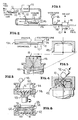
- Figure 1 is a schematic view showing the method of forming a barrier metal foil closure panel insert in accordance with this invention.
- FIG. 2 is an enlarged fragmentary elevational view of the insert showing the general details thereof.
- Figure 3 is an exploded perspective view with parts in section of a mold for injection molding a plastic closure about the insert.
- Figure 4 is an elevational view with parts in section of the closed mold of Figure 3 and shows a plastic closure being injection molded.
- Figure 5 is an elevational view with parts broken away and shown in section of an apparatus for spin-lining the composite closure with a plastisol gasketing compound.
- Figure 6 is a schematic elevational view with parts broken away and shown in section of the plastisol gasketing material being fused.
- FIG. 1 wherein there is illustrated the method of forming the barrier metal foil closure panel insert, which insert is generally identified by the numeral 10.
- a metal foil web 12 which is preferably in the form of a dead soft aluminum foil having a thickness on the order of 0.0381 mm. (1.5 mil).
- the web 12 is conveyed through a direct gravure coating apparatus, generally identified by the numeral 14, wherein a coating 16 is applied to one face or surface of the web 12.
- the coating 16 is preferably applied as a solvent based 50% solids phenolic/vinyl chloride terpolymer organosol identified by the numeral 18 with the gravure coating apparatus using a 65 line gravure cylinder 20.
- the coated web is then passed through an oven 22 which is maintained at an air temperature on the order of 232°C. with the oven dwell time being on the order of 27 seconds.
- the weight of the dried coating 16 is on the order of 7.38 lbs./ream or 1.19 mg/cm2. (7.7mg/in.2).
- the other face or surface of the web 12 is provided with a coating 24 utilizing a direct gravure coating apparatus generally identified by the numeral 26.
- the coating apparatus 26 applies a solvent based 12% solids polyolefin carboxylic acid copolymer primer dispersion 28 which may include polyethylene or polypropylene copolymers and homopolymers to form the coating 24.
- the coating apparatus 26 includes a 65 line gravure cylinder 30.
- the coated web 12 is then passed through an oven 32 having an air temperature on the order of 232°C. (450°F.) with an oven dwell time on the order of 20 seconds.
- the resultant dried coating 24 has a film weight on the order of 1.60 lbs./ream or 0.26 mg/cm2. (1.68 mg/in.2).
- a layer 34 of a thermoplastic polyolefin, preferably polypropylene homopolymer is applied to the coating 24 .
- the layer 34 has a thickness on the order of 0.0762 mm. (3 mil) and is either applied as an extrusion coat utilizing an extruder 36 as shown in Figure 1, or the layer 34 may be applied as a film to the coating 24 by conventional hot roll hip lamination at about 190°C.
- the resultant composite web material passes into a die cutting apparatus 40 which die cuts from the composite web 38 the inserts 10.
- a typical insert 10 includes a central aluminum foil layer.
- Each insert 10 is placed in an injection mold for a closure, the injection mold being generally identified by the numeral schematically illustrated and includes a base 44 having an upwardly extending core 46 and a top mold member 48.
- the core 46 projects above the base and the insert 10 is seated thereon and held in place by a vacuum drawn through passages 50.
- the core is particularly adapted to define internal threads on a resultant closure although the mold 42 may be constructed so as to provide the closure with lugs or other suitable retaining means.
- the mold 42 is presented to an injection nozzle 52 through which a polyolefin e.g. polypropylene is injected into the mold cavity to form a polpropylene closure member generally identified by the numeral 54.
- a polyolefin e.g. polypropylene
- the polypropylene homopolymer layer 34 is heat bonded to the newly injected polypropylene. In this manner, the insert 10 becomes a fixed and bonded part of the closure 54 leaving exposed the organosol surface 16.
- the closure 54 After the closure 54 has been formed in the injection mold 42, the closure is mounted in a fixture 56 which is part of a spin-lining apparatus including a suitable dispensing gun 58.
- the fixture 56 is preferably provided with vacuum passages 59 to retain the closure 54 in place during the spin application of a plastisol gasket 60.
- the gasket 60 may either be an annular gasket or an overall gasket and has a thickness in the range of 0.889 mm. to 1.524 mm. (.035 to .060 inch).
- the coated closure 54 is then subjected to a convection and/or induction or a dielectric heating apparatus to effect a fusion of the gasket 60 and the bonding thereof to the organosol coating 16.
- a convection and/or induction or a dielectric heating apparatus to effect a fusion of the gasket 60 and the bonding thereof to the organosol coating 16.
- a heating fixture is schematically shown in Figure 6 and identified by the numeral 62.
- the resultant closure member 54 includes a body 64 having an integral end panel 66 and generally a base lip 68.
- the insert 10 has the layer 34 thereof bonded to the end panel 66 and is further interlocked with the body 64 of the closure 54.
- the body 64 as illustrated, is provided with internal securing threads 70 although the body may be provided with other types of securing means, including lugs and the like.
Landscapes
- Engineering & Computer Science (AREA)
- Mechanical Engineering (AREA)
- Laminated Bodies (AREA)
- Injection Moulding Of Plastics Or The Like (AREA)
- Closures For Containers (AREA)
Claims (21)
- Aus einer Metallfolie bestehender, sperrschichtbildender Einsatz (10) für einen Kunststoffverschluß mit einer aus einer Metallfolie (12) bestehenden Schicht, einem Haftgrund (24) auf einer Fläche der aus der Metallfolie bestehenden Schicht, einer mit dem Haftgrund stoffschlüssig verbundenen Schicht (34) aus einem Kunststoffbindemittel und einem Organosolüberzug (16) auf der entgegengesetzten Fläche der aus der Metallfolie bestehenden Schicht.
- Einsatz nach Anspruch 1, dadurch gekennzeichnet, daß die Rindemittelschicht aus einem thermoplastischen Polyolefin mit einer Dicke in einer Größenordnung von 0,0762 mm besteht.
- Einsatz nach Anspruch 1, dadurch gekennzeichnet, daß die aus der Metallfolie bestehende Schicht (12) aus einer Folie aus totweichem Aluminium besteht.
- Einsatz nach Anspruch 3, dadurch gekennzeichnet, daß die aus einer Metallfolie bestehende Schicht (12) eine Dicke in einer Größenordnung von 0,0381 mm hat.
- Einsatz nach Anspruch 1, dadurch gekennzeichnet, daß der Haftgrund (24) ein solcher ist, mit dem ein thermoplastisches Polyolefin direkt stoffschlüssig verbindbar ist.
- Einsatz nach Anspruch 1, dadurch gekennzeichnet, daß der Haftgrund (24) eine Lösungsmittel und 12% Feststoff enthaltende Dispersion eines Polypropylen-Carbonsäure-Copolymers ist.
- Einsatz nach Anspruch 6, dadurch gekennzeichnet, daß die Kunststoffbindemittelschicht (34) aus Polypropylen besteht.
- Einsatz nach Anspruch 6, dadurch gekennzeichnet, daß der Haftgrund (24) ein im Tiefdruck aufgetragenes Lösungsmittel ist.
- Einsatz nach Anspruch 1, dadurch gekennzeichnet, daß das Organosol (16) ein Lösungsmittel und 50% Feststoff enthaltendes Organosol eines Phenolharz/Vinylchlorid-Terpolymers ist.
- Einsatz nach Anspruch 9, dadurch gekennzeichnet, daß das Organosol (16) in der Wärme mit einer Plastisoldichtmasse stoffschlüssig verbindbar ist.
- Einsatz nach Anspruch 9, dadurch gekennzeichnet, daß das Organosol ein im Tiefdruck aufgetragenes Lösungsmittel ist.
- Einsatz nach Anspruch 6, dadurch gekennzeichnet, daß der Haftgrund (24) ein Flächengewicht in der Grüßenordnung von 0,26 mg/cm² hat.
- Einsatz nach Anspruch 9, dadurch gekennzeichnet, daß das Organisol (16) ein Flächengewicht in der Größenordnung von 1,19 mg/cm³ hat.
- Verfahren zum Herstellen eines Verschlußplatteneinsatzes (10) für einen Kunststoffverschluß mit folgenden Schritten: es wird eine aus einer Metallfolie bestehende Schicht (12) verwendet, eine Fläche der aus der Metallfolie bestehenden Schicht wird mit einem Organosol (16) überzogen, die entgegengesetzte Fläche der aus der Metallfolie bestehenden Schicht wird mit einem Haftgrund (24) überzogen, auf den Haftgrund wird eine Schicht aus einem thermoplastischen Polyolefin (34) aufgetragen und mit dem Haftgrund stoffschlüssig verbunden, und dann werden von der so überzogenen Materialbahn einzelne Einsätze abgeschnitten.
- Verfahren nach Anspruch 14, dadurch gekennzeichnet, daß jeder der genannten Überzüge in Form eines Materials auf Lösungsmittelbasis mit einem Tiefdruckzylinder (20, 30) aufgetragen wird.
- Verfahren nach Anspruch 15, dadurch gekennzeichnet, daß die Überzüge beim Durchwandern eines Ofens (32) getrocknet werden.
- Verfahren nach Anspruch 15, dadurch gekennzeichnet, daß die Überzüge nacheinander aufgetragen werden und nach jedem Auftrageschritt die überzogene Bahn durch einen Ofen (32) geführt wird.
- Verfahren nach Anspruch 14, dadurch gekennzeichnet, daß jeder Einsatz (10) in ein Spritzgießwerkzeug (42) gelegt und um den Einsatz (10) herum ein eine Endplatte (66) besitzender Kunststoffverschluß (10) im Spritzguß derart hergestellt wird, daß die Schicht aus dem thermoplastischen Polyolefin (34) mit der Endplatte (66) des Verschlusses direkt stoffschlüssig verbunden wird.
- Verfahren nach Anspruch 18, dadurch gekennzeichnet, daß auf den Organosolüberzug (16) des den Einsatz (10) enthaltenden Kunststoffverschlusses (54) eine Plastisoldichtung (60) aufgetragen wird.
- Verschlußanordnung mit einem im Spritzguß hergestellten Verschlußteil (54), der aus Polypropylen besteht und einen Körper (64) und eine Endplatte (66) besitzt, ferner mit einem zur dichten Anlage an einem in dem Körper sitzenden Rehälter dienenden Einsatz (10), der aus einem Schichtstoff besteht, der eine aus einer Metallfolie bestehende Sperrschicht besitzt und der in der Wärme direkt mit der Endplatte (66) stoffschlüssig verbunden worden ist, und mit einer Plastisoldichtung (60), die der Einsatz im Abstand von der Endplatte trägt.
- Verschlußanordnung nach Anspruch 20, dadurch gekennzeichnet, daß der Körper (64) um einen Umfangsrand des Einsatzes (10) herum geformt ist.
Priority Applications (3)
| Application Number | Priority Date | Filing Date | Title |
|---|---|---|---|
| US07/025,635 US4774134A (en) | 1987-03-13 | 1987-03-13 | Low oxygen barrier type plastic closure with an adhered gasketing compound and method of forming same |
| DE8888104123T DE3875106D1 (de) | 1988-03-15 | 1988-03-15 | Mit beschraenkter sauerstoffdurchlaessigkeit versehener plastikverschluss mit angeklebter abdichtungsverbindung und verfahren zur herstellung desselben. |
| EP19880104123 EP0332725B1 (de) | 1988-03-15 | 1988-03-15 | Mit beschränkter Sauerstoffdurchlässigkeit versehener Plastikverschluss mit angeklebter Abdichtungsverbindung und Verfahren zur Herstellung desselben |
Applications Claiming Priority (1)
| Application Number | Priority Date | Filing Date | Title |
|---|---|---|---|
| EP19880104123 EP0332725B1 (de) | 1988-03-15 | 1988-03-15 | Mit beschränkter Sauerstoffdurchlässigkeit versehener Plastikverschluss mit angeklebter Abdichtungsverbindung und Verfahren zur Herstellung desselben |
Publications (2)
| Publication Number | Publication Date |
|---|---|
| EP0332725A1 EP0332725A1 (de) | 1989-09-20 |
| EP0332725B1 true EP0332725B1 (de) | 1992-09-30 |
Family
ID=8198811
Family Applications (1)
| Application Number | Title | Priority Date | Filing Date |
|---|---|---|---|
| EP19880104123 Expired EP0332725B1 (de) | 1987-03-13 | 1988-03-15 | Mit beschränkter Sauerstoffdurchlässigkeit versehener Plastikverschluss mit angeklebter Abdichtungsverbindung und Verfahren zur Herstellung desselben |
Country Status (2)
| Country | Link |
|---|---|
| EP (1) | EP0332725B1 (de) |
| DE (1) | DE3875106D1 (de) |
Cited By (1)
| Publication number | Priority date | Publication date | Assignee | Title |
|---|---|---|---|---|
| DE102004063109A1 (de) * | 2004-12-22 | 2006-07-13 | 3H Kunststofftechnik Tintelnot Gmbh | Verfahren und Mittel zum Verbinden und/oder Abdichten von Teilen |
Families Citing this family (4)
| Publication number | Priority date | Publication date | Assignee | Title |
|---|---|---|---|---|
| FR2703029B1 (fr) * | 1993-03-26 | 1995-05-24 | Capsules Metalliques Ste Lorra | Procédé pour réaliser un dispositif de bouchage pour un récipient, et dispositif de bouchage obtenu. |
| DE19616616C2 (de) * | 1996-04-25 | 1999-04-08 | Alfelder Kunststoffw Meyer H | Dichtungsscheibe für eine Verschlußkappe für Behältnisse |
| SE0200434D0 (sv) | 2002-02-13 | 2002-02-13 | Modulpac Ab | Plastkapsyl och sätt att tillverka denna |
| US9150328B2 (en) | 2009-10-28 | 2015-10-06 | Sonoco Development, Inc. | Container assembly having a heat-sealed metal end, a metal end therefor, and a method for making same |
Family Cites Families (3)
| Publication number | Priority date | Publication date | Assignee | Title |
|---|---|---|---|---|
| US3928109A (en) * | 1972-09-11 | 1975-12-23 | Phoenix Closures Inc | Method of assembling and bonding a laminated liner within a closure member |
| US4436478A (en) * | 1981-07-27 | 1984-03-13 | The West Company | Apparatus for making molded articles |
| JPS61111335A (ja) * | 1984-11-05 | 1986-05-29 | Dainippon Toryo Co Ltd | プラスチツク成形方法 |
-
1988
- 1988-03-15 EP EP19880104123 patent/EP0332725B1/de not_active Expired
- 1988-03-15 DE DE8888104123T patent/DE3875106D1/de not_active Expired - Lifetime
Cited By (1)
| Publication number | Priority date | Publication date | Assignee | Title |
|---|---|---|---|---|
| DE102004063109A1 (de) * | 2004-12-22 | 2006-07-13 | 3H Kunststofftechnik Tintelnot Gmbh | Verfahren und Mittel zum Verbinden und/oder Abdichten von Teilen |
Also Published As
| Publication number | Publication date |
|---|---|
| EP0332725A1 (de) | 1989-09-20 |
| DE3875106D1 (de) | 1992-11-05 |
Similar Documents
| Publication | Publication Date | Title |
|---|---|---|
| US4573596A (en) | Plastic container with vapor barrier | |
| EP0341044B1 (de) | Kunststoffbehälter und Verfahren zu seiner Herstellung | |
| US4756437A (en) | Closure cap with vapor impermeable lamina | |
| KR950001847B1 (ko) | 개봉 용이성 용기 및 그의 제조방법 | |
| US4844270A (en) | Screw cap jar | |
| US2620939A (en) | Sealing closure for containers | |
| EP1487710B1 (de) | Stopfen | |
| US4774134A (en) | Low oxygen barrier type plastic closure with an adhered gasketing compound and method of forming same | |
| US3385470A (en) | Containers | |
| US4076570A (en) | Process for the production of a multiple layer laminate | |
| EP0038108A2 (de) | Thermoplastische Verpackungsfolien mit verbesserten Heissiegeleigenschaften | |
| JPS6228355A (ja) | ヒ−トシ−ル容器 | |
| US3397101A (en) | Method of improving the heat sealing qualities of thermoplastic film oriented by stretching | |
| CA2778253A1 (en) | Container assembly having a heat-sealed metal end, a metal end therefor, and a method for making same | |
| US4391863A (en) | Peel resistant coextruded sheet | |
| CA2276133C (en) | Method for making tubular containers | |
| EP0332725A1 (de) | Mit beschränkter Sauerstoffdurchlässigkeit versehener Plastikverschluss mit angeklebter Abdichtungsverbindung und Verfahren zur Herstellung desselben | |
| EP0306820A1 (de) | Kunststoffkappe mit niedriger Sauerstoffdurchlässigkeit sowie Verfahren zu ihrer Herstellung | |
| CA1304634C (en) | Low oxygen barrier type plastic closure with an adhered gasketing compound and method of forming same | |
| JP4030137B2 (ja) | イージーピール容器およびその製造方法 | |
| EP0384606A1 (de) | Verbundstoffe aus Metall und Polymer | |
| JP3776491B2 (ja) | バリア性成形品及びその製造方法 | |
| JP3624034B2 (ja) | ガスバリヤー性容器及びその製造方法 | |
| JP2020189649A (ja) | 複合容器及びその製造方法 | |
| US3220907A (en) | Method of making a bottle closure |
Legal Events
| Date | Code | Title | Description |
|---|---|---|---|
| PUAI | Public reference made under article 153(3) epc to a published international application that has entered the european phase |
Free format text: ORIGINAL CODE: 0009012 |
|
| AK | Designated contracting states |
Kind code of ref document: A1 Designated state(s): BE DE ES FR GB IT NL |
|
| 17P | Request for examination filed |
Effective date: 19900223 |
|
| 17Q | First examination report despatched |
Effective date: 19910626 |
|
| GRAA | (expected) grant |
Free format text: ORIGINAL CODE: 0009210 |
|
| AK | Designated contracting states |
Kind code of ref document: B1 Designated state(s): BE DE ES FR GB IT NL |
|
| PG25 | Lapsed in a contracting state [announced via postgrant information from national office to epo] |
Ref country code: IT Free format text: LAPSE BECAUSE OF FAILURE TO SUBMIT A TRANSLATION OF THE DESCRIPTION OR TO PAY THE FEE WITHIN THE PRE;WARNING: LAPSES OF ITALIAN PATENTS WITH EFFECTIVE DATE BEFORE 2007 MAY HAVE OCCURRED AT ANY TIME BEFORE 2007. THE CORRECT EFFECTIVE DATE MAY BE DIFFERENT FROM THE ONE RECORDED.SCRIBED TIME-LIMIT Effective date: 19920930 Ref country code: DE Effective date: 19920930 Ref country code: BE Effective date: 19920930 Ref country code: NL Effective date: 19920930 Ref country code: FR Effective date: 19920930 Ref country code: ES Free format text: THE PATENT HAS BEEN ANNULLED BY A DECISION OF A NATIONAL AUTHORITY Effective date: 19920930 |
|
| REF | Corresponds to: |
Ref document number: 3875106 Country of ref document: DE Date of ref document: 19921105 |
|
| EN | Fr: translation not filed | ||
| PG25 | Lapsed in a contracting state [announced via postgrant information from national office to epo] |
Ref country code: GB Effective date: 19930315 |
|
| NLV1 | Nl: lapsed or annulled due to failure to fulfill the requirements of art. 29p and 29m of the patents act | ||
| PLBE | No opposition filed within time limit |
Free format text: ORIGINAL CODE: 0009261 |
|
| STAA | Information on the status of an ep patent application or granted ep patent |
Free format text: STATUS: NO OPPOSITION FILED WITHIN TIME LIMIT |
|
| 26N | No opposition filed | ||
| GBPC | Gb: european patent ceased through non-payment of renewal fee |
Effective date: 19930315 |