EP0332732A2 - Dispositif pour effectuer des déterminations photométriques et spectrophotométriques et des réactions chimiques microscopiques, procédé apparenté - Google Patents
Dispositif pour effectuer des déterminations photométriques et spectrophotométriques et des réactions chimiques microscopiques, procédé apparenté Download PDFInfo
- Publication number
- EP0332732A2 EP0332732A2 EP88109707A EP88109707A EP0332732A2 EP 0332732 A2 EP0332732 A2 EP 0332732A2 EP 88109707 A EP88109707 A EP 88109707A EP 88109707 A EP88109707 A EP 88109707A EP 0332732 A2 EP0332732 A2 EP 0332732A2
- Authority
- EP
- European Patent Office
- Prior art keywords
- microcell
- capillary tube
- liquid
- container
- photometric
- Prior art date
- Legal status (The legal status is an assumption and is not a legal conclusion. Google has not performed a legal analysis and makes no representation as to the accuracy of the status listed.)
- Withdrawn
Links
- 239000000126 substance Substances 0.000 title claims description 6
- 238000002798 spectrophotometry method Methods 0.000 title claims description 5
- 239000007788 liquid Substances 0.000 claims abstract description 22
- 238000004458 analytical method Methods 0.000 claims abstract description 17
- 238000000034 method Methods 0.000 claims abstract description 10
- 239000003153 chemical reaction reagent Substances 0.000 claims abstract description 8
- 238000005070 sampling Methods 0.000 claims abstract description 7
- 239000008280 blood Substances 0.000 claims description 14
- 210000004369 blood Anatomy 0.000 claims description 14
- 239000000463 material Substances 0.000 claims description 2
- BPYKTIZUTYGOLE-IFADSCNNSA-N Bilirubin Chemical compound N1C(=O)C(C)=C(C=C)\C1=C\C1=C(C)C(CCC(O)=O)=C(CC2=C(C(C)=C(\C=C/3C(=C(C=C)C(=O)N\3)C)N2)CCC(O)=O)N1 BPYKTIZUTYGOLE-IFADSCNNSA-N 0.000 description 8
- 239000011521 glass Substances 0.000 description 5
- 238000005259 measurement Methods 0.000 description 4
- 238000006243 chemical reaction Methods 0.000 description 3
- 230000003287 optical effect Effects 0.000 description 3
- 238000005375 photometry Methods 0.000 description 3
- 230000005855 radiation Effects 0.000 description 2
- 238000000926 separation method Methods 0.000 description 2
- 241001391944 Commicarpus scandens Species 0.000 description 1
- 230000036765 blood level Effects 0.000 description 1
- 238000011534 incubation Methods 0.000 description 1
- 238000002347 injection Methods 0.000 description 1
- 239000007924 injection Substances 0.000 description 1
- 239000005304 optical glass Substances 0.000 description 1
- 238000003825 pressing Methods 0.000 description 1
- 230000000284 resting effect Effects 0.000 description 1
- 239000007787 solid Substances 0.000 description 1
Images


Classifications
-
- B—PERFORMING OPERATIONS; TRANSPORTING
- B01—PHYSICAL OR CHEMICAL PROCESSES OR APPARATUS IN GENERAL
- B01L—CHEMICAL OR PHYSICAL LABORATORY APPARATUS FOR GENERAL USE
- B01L3/00—Containers or dishes for laboratory use, e.g. laboratory glassware; Droppers
- B01L3/50—Containers for the purpose of retaining a material to be analysed, e.g. test tubes
- B01L3/502—Containers for the purpose of retaining a material to be analysed, e.g. test tubes with fluid transport, e.g. in multi-compartment structures
- B01L3/5021—Test tubes specially adapted for centrifugation purposes
-
- B—PERFORMING OPERATIONS; TRANSPORTING
- B01—PHYSICAL OR CHEMICAL PROCESSES OR APPARATUS IN GENERAL
- B01L—CHEMICAL OR PHYSICAL LABORATORY APPARATUS FOR GENERAL USE
- B01L3/00—Containers or dishes for laboratory use, e.g. laboratory glassware; Droppers
- B01L3/54—Labware with identification means
- B01L3/545—Labware with identification means for laboratory containers
- B01L3/5453—Labware with identification means for laboratory containers for test tubes
Definitions
- the present invention refers to a device and the related procedure for photometric and spectrophotometric determinations on liquids of any type, such as, for example, sampling and measurement of blood levels of bilirubin in pediatrics, as well as chemical microreactions.
- Measurement of bilirubin in the plasma of newborns is done essentially by photometric methods, i.e. by illuminating the plasma container, which must be transparent to the radiation used and is generally made of glass, with a photometric lamp.
- Devices that allow small amounts of blood to be drawn from the patient, based essentially on the use of a glass capillary tube the bottom end of which is brought into contact with a drop of blood from the newborn.
- the blood is drawn up into the tube, which has an internal diameter of approximately 1,6 mm., by capillarity.
- the bottom end of the tube filled with blood is then pressed down on a piece of a substance such as plasticine, about 10 mm thick, so that the plasticine that enters the opening forms a stopper for the capillary tube.
- the plasma is subsequently separated from the corpuscular part of the blood by placing the stopped capillary, with its axis horizontal and the plasticine stopper facing outwards, in a centrifuge. In this manner, the corpuscular part of the blood collects near the plasticine stopper, while the plasma phase collects at the opposite end.
- the capillary according to the known method, is disposed vertically, with the plasma in the upper part, and is placed directly on the optical axis of the bilirubinometer, thus acting as a phtometric cell.
- a second known device also entails drawing the blood with a glass capillary tube, which is then stopped and centrifuged in a similar way to that indicated above.
- the capillary tube with the separated plasma and corpuscular part of the blood is then cut with an injection vial saw to divide the two sections, one containing the plasma and the other the corpuscular part.
- the plasma is then poured into an optical glass microcell with flat parallel sides 0,25 mm apart, so that an optically perfect layer is obtained and the bilirubin can be measured without photometric or methodological errors.
- the optical system does not require excessive light intensities and thus its life can be up to a hundredfold that of the preceding system.
- the purpose of the present invention is to provide a sampling device for photometric and spectrophotometric analysis on any type of liquid, such as, for example, analysis of blood bilirubin, capable of overcoming the above problems, i.e. that permits simple, safe drawing of the liquid for analysis, separation of the phases making up the liquid if necessary and accurate analysis.
- a further purpose is to provide a device that also permits other analyses on the liquid, involving chemical microreactions, using suitable reagents.
- a further purpose is to be able to identify the sampling and analysis device with a suitable code that can be read by a scanner attached to the analyzer, containing, as well as identification of the sample to be analyzed, any information on characteristic analysis parmeters so that this code serves to control all the working parameters of the analyzer (wave length of the light radiation, conversion factors, temperature, duration and intensity of shaking, incubation, times etc.).
- a suitable code that can be read by a scanner attached to the analyzer, containing, as well as identification of the sample to be analyzed, any information on characteristic analysis parmeters so that this code serves to control all the working parameters of the analyzer (wave length of the light radiation, conversion factors, temperature, duration and intensity of shaking, incubation, times etc.).
- the main purpose has been achieved by providing a device for sampling liquids, particularly blood, for photometric and spectrophotometric analysis and a related sampling and analysis process as stated in the attached claims 1 and 8.
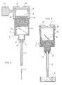
- FIGS. 1 and 2 show the device 1 consisting of a capillary tube 2 and a microcell 3 set above said capillary and integral with it.
- the microcell 3 has flat parallel surfaces, preferably set 0,25 mm apart.
- a micropiston 4 is shown, which can be pushed up inside the capillary tube to the desired height.
- the device is operated as follows: the base of the capillary tube 2 is brought into contact with a drop of blood from the patient, which is sucked up by capillarity and reaches a certain height inside the capillary tube.
- the capillary tube 2 is then pressed down on a 10 mm thick piece of plasticine so that the plasticine enters the bottom opening forming a stopper.
- the device is then placed with its axis horizontal, with the plasticine stopper facing towards the outside of the centrifuge rotor, and centrifuged, so that the corpuscular part of the blood is separated from the plasma phase. If centrifuging is not necessary, the next step can be performed immediately.
- the device 1 is placed with its axis vertical again, then the liquid contained in the capillary tube 2 is pushed upward by pressing the capillary down repeatedly on a piece of plasticine, which forms successive stoppers that gradually reach up higher into the capillary 2, or by inserting at the base of the capillary tube a micropiston 4 of plastic material connected to an electronically controlled motor, said piston being inserted to the desired height.
- the plasma stratified in the top part of the capillary tube 2 and pushed by the micropiston 4, thus enters the microcell 3, which can be subjected to photometric analysis with low intensity lamps, giving highly accurate results thanks to the reduced thickness and perfect flatness of the walls 3a and 3b of the microcell 3.
- Figure 3 shows a similar device to the one in the preceding figures, in which analogous components to those already described have been designated by primed numbers, with the sole difference that a piercing element 5 is inserted in the microcell 3′, preferably positioned centrally with respect to the hole in the base of the microcell, which connects the microcell to the capillary tube 2′.
- the capillary tube 2′ the bottom end of which can be inserted into a container 30 of any shape containing the liquid to be drawn, is connected at its top end to the microcell 3′.
- the lower one 31, smaller in volume, will have thin transparent walls, parallel and facing each other, allowing optical measurements to be made perferctly.
- the upper area 32, larger in section, demarcates an upper chamber 32, symmetrical with the lower chamber 31.
- the lower chamber 31 ends in a cylindrical narrowing forming a neck 33 into which the capillary tube 2′ is inserted.
- the connection and seal between the neck and the capillary tube are guaranteed by an elastic sheath 34, having a clindrical shape and variable diameter, the top of wich encloses the neck 33 and the bottom the capillary tube 2′.
- This elastic sheath 34 serves as the connection for the arm of a mechanical shaker designed to shake the liquids inside.
- a piercing element 5 consisting, for example, of a cylindrical element 11 the top edge of which is cut slantwise 35.
- a container 37 can be inserted into the upper chamber 32 from above, the base 39 of said container already being prepared for cutting and piercing; the outside diameter of the container 37 is slightly smaller than the inside diameter of the upper chamber 32.
- the desired chemical reagent in the desired physical state (liquid, solid) can be placed inside the container 37.
- the container 37 is provided with a stopper 38 and a vent-hole 40, initially closed by a tear-off seal 41. The circumference of this seal extends beyond the vent-hole 40 and rests on a ledge formed by a further projection 36 of the upper chamber 32.
- the tear-off seal 41 also has a tab 42 bearing codes that can be read by a scanner belonging to the analyzer and contain identification of the specimen for analysis, as well as all information concerning the parameters that the scanner must read for the analysis to be performed correctly.
- the tear-off seal 41 is removed, upon which air can enter the container 37.
- This container can be pushed downward, manually or automatically, until its base 39 is pierced by the cutting edge 35 and the walls of the container 37 descend to occupy space 36.
- the chemical reagent is thus mixed with the liquid to be analyzed contained in the cell 3′ and reacts.
- the tear-off seal 41 prevents the container from being accidentally inserted into the microcell during transport or handling and its base 39 thus being cut.
- the arm of a shaker sets the elastic neck 34 in vibration to mix the reagent and the specimen, so that after the time required for the reaction, measurement can be carried out in the cell 31.
Landscapes
- Chemical & Material Sciences (AREA)
- Health & Medical Sciences (AREA)
- Analytical Chemistry (AREA)
- Clinical Laboratory Science (AREA)
- Chemical Kinetics & Catalysis (AREA)
- General Health & Medical Sciences (AREA)
- Hematology (AREA)
- Automatic Analysis And Handling Materials Therefor (AREA)
- Investigating Or Analysing Biological Materials (AREA)
Applications Claiming Priority (2)
| Application Number | Priority Date | Filing Date | Title |
|---|---|---|---|
| IT8819788A IT1216101B (it) | 1988-03-15 | 1988-03-15 | Microreazioni chimiche e relativo dispositivo atto a realizzare procedimento. determinazioni fotometriche e spettrofometriche nonche' |
| IT19788 | 1988-03-15 |
Publications (2)
| Publication Number | Publication Date |
|---|---|
| EP0332732A2 true EP0332732A2 (fr) | 1989-09-20 |
| EP0332732A3 EP0332732A3 (fr) | 1990-08-29 |
Family
ID=11161218
Family Applications (1)
| Application Number | Title | Priority Date | Filing Date |
|---|---|---|---|
| EP88109707A Withdrawn EP0332732A3 (fr) | 1988-03-15 | 1988-06-17 | Dispositif pour effectuer des déterminations photométriques et spectrophotométriques et des réactions chimiques microscopiques, procédé apparenté |
Country Status (2)
| Country | Link |
|---|---|
| EP (1) | EP0332732A3 (fr) |
| IT (1) | IT1216101B (fr) |
Cited By (3)
| Publication number | Priority date | Publication date | Assignee | Title |
|---|---|---|---|---|
| DE19535046A1 (de) * | 1995-09-21 | 1997-03-27 | Eppendorf Geraetebau Netheler | System zum Pipettieren und photometrischen Messen von Proben |
| WO1998036260A1 (fr) * | 1997-02-15 | 1998-08-20 | Rts Thurnall Plc | Microtube individuel avec bouchon a cloison et procede |
| US7986406B2 (en) | 2005-11-22 | 2011-07-26 | Bp Chemicals Limited | Method and apparatus for spectroscopic analysis |
Family Cites Families (7)
| Publication number | Priority date | Publication date | Assignee | Title |
|---|---|---|---|---|
| US2655152A (en) * | 1951-01-30 | 1953-10-13 | Abbott Lab | Blood sampling apparatus |
| US3263554A (en) * | 1961-12-26 | 1966-08-02 | Beckman Instruments Inc | Cuvette with means for controlled volumetric displacement |
| DE1598269A1 (de) * | 1965-05-27 | 1971-12-23 | Ceskoslovenska Akademie Ved | Kuevette fuer Durchflussphotometer |
| FR1538351A (fr) * | 1967-04-18 | 1968-09-06 | Roussel Uclaf | Dispositif perfectionné de cuve à échantillon pour mesures optiques |
| US3572952A (en) * | 1968-02-20 | 1971-03-30 | American Optical Corp | Float cuvette |
| IT998660B (it) * | 1973-09-27 | 1976-02-20 | Erba Carlo Spa | Cartuccia analitica contenente i reagenti specifici per determina zioni spettrofotometriche |
| DE3405292A1 (de) * | 1984-02-15 | 1985-09-05 | Eppendorf Gerätebau Netheler + Hinz GmbH, 2000 Hamburg | Verfahren zum durchfuehren von probenanalysen sowie rack zur durchfuehrung des verfahrens |
-
1988
- 1988-03-15 IT IT8819788A patent/IT1216101B/it active
- 1988-06-17 EP EP88109707A patent/EP0332732A3/fr not_active Withdrawn
Cited By (5)
| Publication number | Priority date | Publication date | Assignee | Title |
|---|---|---|---|---|
| DE19535046A1 (de) * | 1995-09-21 | 1997-03-27 | Eppendorf Geraetebau Netheler | System zum Pipettieren und photometrischen Messen von Proben |
| DE19535046C2 (de) * | 1995-09-21 | 1998-04-16 | Eppendorf Geraetebau Netheler | Handgerät zum Pipettieren und photometrischen Messen von Proben |
| US5844686A (en) * | 1995-09-21 | 1998-12-01 | Eppendorf-Netheler-Hinz, Gmbh | System for pipetting and photometrically evaluating samples |
| WO1998036260A1 (fr) * | 1997-02-15 | 1998-08-20 | Rts Thurnall Plc | Microtube individuel avec bouchon a cloison et procede |
| US7986406B2 (en) | 2005-11-22 | 2011-07-26 | Bp Chemicals Limited | Method and apparatus for spectroscopic analysis |
Also Published As
| Publication number | Publication date |
|---|---|
| EP0332732A3 (fr) | 1990-08-29 |
| IT1216101B (it) | 1990-02-22 |
| IT8819788A0 (it) | 1988-03-15 |
Similar Documents
| Publication | Publication Date | Title |
|---|---|---|
| US4310488A (en) | Sample or reagent container for analyzers | |
| US5112490A (en) | Sample filtration, separation and dispensing device | |
| US5833630A (en) | Sample collection device | |
| KR101009447B1 (ko) | 체액 샘플링, 전처리 및 투입장치 및 방법 | |
| US5163582A (en) | Apparatus and method for aliquotting blood serum or blood plasma | |
| Cunningham | Fluidics and sample handling in clinical chemical analysis | |
| US5211310A (en) | Apparatus and method for dispensing phases of blood | |
| US8158062B2 (en) | Disposable fluid sample collection device | |
| KR100562179B1 (ko) | 중공형 절두체를 사용하는 분석물 농도 측정방법 | |
| US5645798A (en) | Test elements in sealed chambers for analyzing compounds contained in liquid samples | |
| US5555920A (en) | Method and apparatus for aliquotting blood serum or blood plasma | |
| US3992150A (en) | Method and equipment for speedy preparation of test liquids | |
| US5257984A (en) | Blood collector | |
| DK157263B (da) | Reaktionskuvette og reaktionsbakke bestaaende af et antal af saadanne reaktionskuvetter | |
| CA2011100C (fr) | Mesure de couches de matieres centrifugees dans tube sous vide | |
| CN1969184A (zh) | 样本采集、处理和分析组件 | |
| EP1684904B1 (fr) | Cuve a reactifs | |
| BR0209540B1 (pt) | Aparelho, cartucho e dispositivo de exame e uso do aparelho de exame | |
| EP0746754A1 (fr) | Recipient pour appareil d'essai automatise | |
| JPH01257268A (ja) | 液体サンプルの稀釈及び混合のための装置及び方法 | |
| US6689318B1 (en) | Apparatus for analysis of physiological fluids | |
| EP0217000A2 (fr) | Système de récipient à réactifs pour un appareil d'analyse clinique | |
| EP4190451A1 (fr) | Pointe de pipette et système de pipette pour la collecte de sang capillaire | |
| EP0114874A1 (fr) | Recipient pour petites quantites de liquides | |
| US5000922A (en) | Sample filtration, separation and dispensing device |
Legal Events
| Date | Code | Title | Description |
|---|---|---|---|
| PUAI | Public reference made under article 153(3) epc to a published international application that has entered the european phase |
Free format text: ORIGINAL CODE: 0009012 |
|
| AK | Designated contracting states |
Kind code of ref document: A2 Designated state(s): DE ES FR GB IT |
|
| PUAL | Search report despatched |
Free format text: ORIGINAL CODE: 0009013 |
|
| AK | Designated contracting states |
Kind code of ref document: A3 Designated state(s): DE ES FR GB IT |
|
| STAA | Information on the status of an ep patent application or granted ep patent |
Free format text: STATUS: THE APPLICATION IS DEEMED TO BE WITHDRAWN |
|
| 18D | Application deemed to be withdrawn |
Effective date: 19910301 |