EP0332748B1 - Plateforme modulaire pour échafaudage volant - Google Patents
Plateforme modulaire pour échafaudage volant Download PDFInfo
- Publication number
- EP0332748B1 EP0332748B1 EP88118687A EP88118687A EP0332748B1 EP 0332748 B1 EP0332748 B1 EP 0332748B1 EP 88118687 A EP88118687 A EP 88118687A EP 88118687 A EP88118687 A EP 88118687A EP 0332748 B1 EP0332748 B1 EP 0332748B1
- Authority
- EP
- European Patent Office
- Prior art keywords
- posts
- tubular member
- platform
- outer tubular
- fastened
- Prior art date
- Legal status (The legal status is an assumption and is not a legal conclusion. Google has not performed a legal analysis and makes no representation as to the accuracy of the status listed.)
- Expired
Links
- 239000000725 suspension Substances 0.000 claims description 16
- 239000002184 metal Substances 0.000 claims description 5
- 238000000034 method Methods 0.000 description 6
- 238000003466 welding Methods 0.000 description 6
- 230000008878 coupling Effects 0.000 description 2
- 238000010168 coupling process Methods 0.000 description 2
- 238000005859 coupling reaction Methods 0.000 description 2
- 230000000284 resting effect Effects 0.000 description 2
- 229910000831 Steel Inorganic materials 0.000 description 1
- 238000004873 anchoring Methods 0.000 description 1
- 230000004323 axial length Effects 0.000 description 1
- 230000000694 effects Effects 0.000 description 1
- 239000002783 friction material Substances 0.000 description 1
- 230000000717 retained effect Effects 0.000 description 1
- 239000010959 steel Substances 0.000 description 1
Images


Classifications
-
- E—FIXED CONSTRUCTIONS
- E04—BUILDING
- E04G—SCAFFOLDING; FORMS; SHUTTERING; BUILDING IMPLEMENTS OR AIDS, OR THEIR USE; HANDLING BUILDING MATERIALS ON THE SITE; REPAIRING, BREAKING-UP OR OTHER WORK ON EXISTING BUILDINGS
- E04G3/00—Scaffolds essentially supported by building constructions, e.g. adjustable in height
- E04G3/28—Mobile scaffolds; Scaffolds with mobile platforms
- E04G3/30—Mobile scaffolds; Scaffolds with mobile platforms suspended by flexible supporting elements, e.g. cables
Definitions
- the invention disclosed herein pertains to a platform module for suspending in space, according to the features of the preamble of claim 1.
- a platform module according to the preamble of claim 1 is known from US-A-4 413 707. Furthermore, a suspended travelling scaffold is known from US-A-3 524 520.
- the catalogue Systémes de significance Peri, edition 6/82, DE-2 119 720 and US-A-3 394 776 disclose several other scaffolds.
- a preferred embodiment comprises an outer tubular vertical post member on which at least one or a vertically spaced apart pair of attachment rings are fastened, preferably by welding.
- the outer tubular post member has an internally threaded nut fastened in what is nominally its upper end.
- a tubular level adjusting screw having an eternal thread screws into the nut internally concentric with the outer tubular post member.
- a load bearing rod extends centrally through the total length of the externally threaded level adjustment screw and the outer tube and also through a concentric inner tubular element in one embodiment.
- An eye nut for hanging a post from a wire rope, chain, tube, rod or other elongated suspension means is threaded onto the upper and lower ends of the rod.
- the suspension wire ropes extend through the internal tubular element and there is a stop element or thrust element fastened to the wire rope.
- the stop element acts as a load carrying thrust bearing.
- the internal tubular element bears on the thrust element which may be washers which are slid on the rod or wire rope and are resting on the lower eye nut which is threaded onto the lower end of the rod or otherwise fastened to the rope.
- the inner tubular element makes a free fit on the load bearing rod or wire rope as the case may be and extends upwardly to the bottom end of the externally threaded tubular adjusting screw.
- the force of the tubular screw reacts against the thrust elements such as the washers on the lower end of the rod or wire rope which washers bear on the eye nut which is screwed onto the lower end of the rod or bears on another form of stop element if a wire rope is used instead of the rod.
- the screw reacts indirectly against the rod or wire rope. This pulls the outer tubular post upwardly relative to the rod or wire rope and, of course, the eye nut or other element at the upper and lower ends remain at the same level. If the level adjusting screw is turned out of the outer tube, the outer tube moves downwardly relative to the load bearing rod or wire rope.
- the post there are pairs of annular attachment members in the form of rings near the upper and lower ends of the outer tubular post.
- the rings are analogous to dishes that have a central hole punched in them whose diameter is about equal to the outside diameter of the outer tubular post.
- the dishes provide upstanding rims.
- the rings are welded to the outer tubular post.
- the rims do not have to be formed as a ring. They could be polygonal or any other configuration.
- Horizontal elongated tubular members constituting runners and trusses connect to the rings by means of connecting members called joints, typical joints being shown in U.S. Patent Nos. 4,445,307 and 4,586,842 which are incorporated herein by reference. It should be understood, however, that other means for joining the runners or trusses to the adjustable posts could be used and that the invention is not limited to using rings with rims.
- Vertically oriented adjustable posts serve as the corners of a platform module. Runners and trusses spanning between the posts can form variously shaped modules such as square, rectangular, polygonal, triangular and even nearly circular modules on which platform planks are placed to provide a surface for the workers.
- the new adjustable posts facilitate a simplified method of erecting a suspended area scaffold on the floor or ground or at a high level in free space.
- the erecting method at a high elevation involves having a ledge or some kind of surface for assemblers to stand on laterally of the area at which the scaffold platform is to be formed. Workers wearing fall-arrest harnesses assemble the first scaffold module by working from the ledge.
- At least four elongated suspension elements such as wire ropes, rods, chains or the like will be anchored to the building above the elevation at which the platform of the scaffolding is to be established. The free ends of the suspension elements will be dangling at the outset in positions which would align vertically with where corners of a platform module will exist.
- An adjustable post is used at each corner.
- wire ropes are used as the suspension elements of the scaffold and that the load is carried by rods extending through the tubular posts.
- workers on the ledge use a pole to swing the two wire ropes that are most remote from the ledge into their possession.
- the eyes of the eye nuts on the upper ends of the rods of the posts are used to fasten an adjustable collar to each of the two wire ropes.
- a first horizontally extending tube, called a runner is then connected by means of joint devices at each end to the pair of rings nearest to the lower ends of the two adjustable posts which are connected to the wire ropes.
- two more runners are fastened in parallelism with each other and perpendicular to the first horizontally extending runner.
- Three sides of a rectangle or square are now formed with the runners if a four-sided platform module is contemplated.
- the last two parallel runners still have free ends.
- the three sided module is usually allowed to yield or swing partly away from the ledge on which the workers are working under the control of a tag line. This positions the free ends of the two side runners nearer to the edge of the ledge.
- the workers on the ledge then pull in the nearest two dangling wire ropes and use the eyes of the eye nuts on two of the adjustable posts to fasten the posts to the ends of the wire ropes. Then the free ends of the parallel side runners are fastened by means of joint devices to the second pair of adjustable posts and another runner is installed in parallelism with the first runner.
- This illustrative assembly with four corner posts connected by runners is allowed to swing outwardly of the ledge so the assembly is supported exclusively on the four wire ropes. If the platform module were to be other than square or other than four-cornered, the procedure would be substantially the same.
- the workers then deposit a few metal planks from the ledge onto the first platform module.
- the planks are like steel channels which span between a parallel pair of runners and provide a temporary platform for the workers which is at a level nearly at the bottom ends of the adjustable posts.
- the workers then get onto the planks at which time load bearing trusses and runners are passed to the workers on the planks.
- Runners are then installed on the uppermost pair of fastening rings on the outer posts perpendicular to the two trusses to form a square or rectangular shape.
- the load bearing trusses are connected with joint devices between posts and onto the uppermost pair of fastening rings on the outer posts.
- Similar platform modules of various shapes can be built sidewise of the original module in any direction since the posts allow for joining runners and trusses in any direction away from the basic module.
- the invention also features a new type of guard rail post.
- the guard rail posts are fastened to the outer tubular members of the adjustable posts at the corners of a scaffold module. Rails are fastened to the guard rail posts to prevent workers from inadvertently walking or falling off the scaffold platform when they are preoccupied with their tasks.
- the post comprises an outer tubular member 10.
- a sleeve 11 is welded to the upper end of outer tubular member 10.
- An internally threaded element such as a nut 12 is welded concentrically and inside of the sleeve 11.
- a tubular externally threaded level adjusting screw 13 is screwed into the nut which is fastened in outer tubular post member 10.
- a round rod or bolt 14 is long enough to extend through the combined length of the adjusting screw 13 and outer tubular member 10.
- the adjusting screw has an axial bore so the screw fits concentrically on the rod.
- the upper end of bolt 14 is threaded and an eye nut 15 is screwed onto the thread and locked with a nut 16.
- Washers 17 are interposed between the bottom of the eye nut 15 and the top of adjusting screw 13.
- a pair of spaced apart bracket plates, one of which 18, is visible, are attached by suitable means, such as welding, to the upper end of adjusting screw 13.
- a handle or crank 19 is pivotally connected with a pin 20 to brackets 18. The crank facilitates turning adjusting screw 13 inwardly and outwardly of nut 12 in outer tubular member 10.
- the bottom end of rod 14 is also threaded and an eye nut 21 is screwed onto the thread and locked by means of a nut 22.
- This nut is preferably secured on the thread of the rod by welding since the post can be disassembled, if desired, by taking off upper nut 16 and eye nut 15.
- the lower end of inner tubular member 24 rests on washers 23 which are retained by eye nut 21.
- Washers 25 are interposed between the lower end of externally threaded tubular adjusting screw 13 and the upper end of inner force-transmitting tubular member 24.
- the lower end of inner tubular member 24 always rests on and reacts against the lower washers 23.
- Outer tubular member 10 is presently in its lowest possible position of adjustment relative to rod 14 in FIGURE 1.
- joint attachment rings 26 and 27 There is an upper pair of joint attachment rings 26 and 27 and a lower pair of rings 28 and 29 welded onto the exterior of outer tubular post member 10.
- These attachment rings are somewhat similar to a dish with a hole in its center for sliding over the outer tube 10.
- the rims of the dish are bent upwardly and downwardly so that there is an annular depression 30 between the rims and the periphery of outer tube 10.
- the configuration of the rims and the annular depression allows for joint devices to be fastened to the upper 26, 27 and lower 28, 29 pairs of rings.
- the joint devices are provided to allow for connecting horizontal members to the new vertically oriented adjustable posts. Typical suitable joint devices are shown in the previously cited U.S. Patent Nos.
- FIGURE 2A The alternative structure in FIGURE 2A is similar in most respects to FIGURE 2 with two exceptions.
- the first is that the inner force-transmitting tube 24 of FIGURE 2 is omitted and the second is that a collar 31 is fastened to rod 14 by welding, preferably.
- a collar 31 is fastened to rod 14 by welding, preferably.
- tubular adjusting screw 13 when tubular adjusting screw 13 is turned in, the screw reacts against collar 13 which is part of the rod so outer platform supporting tubular member 10 rises. Conversely, if the screw 13 is backed out of threaded nut the outer tube moves oppositely or downwardly.
- FIGURE 3 shows a partially assembled scaffolding module.
- wire ropes 40-43 which are initially dangling from some point of attachment above the elevation at which the platform of the scaffolding is to be positioned.
- anchors not shown, are installed somewhere at a high level in the boiler and groups of four related wire ropes for one scaffold would be hung from the anchors.
- workers who may be standing on a ledge 44 or other temporary worker's support, which is shown schematically in FIGURE 3 would use a pole having a hook on its end, not shown, for pulling wire ropes 40 and 41 toward the workers on ledge 44.
- the adjustable posts are generally designated by the reference characters 39A, 39B, 39C and 39D. All of the adjustable posts are hung on the ends of the dangling wire ropes, chains, tubes or rods, 40-43 in due course.
- FIGURE 3 again, now that the pair of wire ropes 40 and 41 most remote from ledge 44 have adjustable posts 39A and 39B hung on them, the posts are connected together by means of a first runner tube 48. Connections are made by joint devices, a typical one of which in FIGURE 3 is marked 35. These joint devices are basically the same as the joints described in the two cited patents. Of course other runner end attachment means such as split clamps, not shown, could be used. A little larger view of a typical joint 35 is shown in FIGURE 7 locked onto the lower pair of rings 28 and 29 on outer axially movable tube 10 of the adjustable post with a tapered wedge 36.
- first runner 48 is connected between the adjustable posts 39A and 39B on wire ropes 40 and 41
- another joint device 35A is fastened to the post for wire rope 40 and a second tubular runner 49 is thereby installed.
- a runner 50 is installed using joint 35B.
- the frame is comprised of first runner 48 and parallel runners 49 and 50 which have free and unattached ends.
- Wire ropes 40 and 41 support the three sided frame which is allowed to swing out somewhat away from ledge 44 but no farther than to have the free ends of runners 49 and 50 remain accessible to the workers on the ledge. Then using another set of joints 35 a fourth runner 51 is installed in parallelism with the first runner 48 so that a four sided frame comprised of tubular runners 48-51 is formed. Since this assembly is now supported on wire ropes 40-43 through the agency of the adjustable posts 39A-39D at the corners, the workers can and do push the assembly away from ledge 44 but within their reach as is the case in FIGURE 3.
- FIGURE 4 shows three planks 55 in place and there are gaps between them so as to constitute a lower temporary platform. The workers now step onto the planks of the temporary platform.
- load bearing trusses 59 and 60 are passed to them and they are installed.
- These trusses have upper horizontal tubular members 61 and 62 which are comparable to runners and they facilitate mounting the trusses to the corner posts with joint devices 35.
- runners 75 and 76 are installed before or after the tresses 59 and 60 are installed.
- the next thing to do is level the structure. This is done by placing a level instrument, not shown, on the top of the truss tubes 61 and 62 and runners 73, 74 and then turning the adjustment screws 13 with the crank handles 9 selectively to variously raise or lower the outer tubes 10 of the adjustment posts as required to obtain a level platform.
- the leveling procedure is to place a level at one of the corners such as to span from runner 75 and truss tube 61, for example.
- the leveling instrument shows level, this level becomes the datum level and leveling is continued along the trust tubes and runners around the structure. Levels are achieved by adjusting the posts.
- the platform planks are not used for leveling because they could be slightly warped.
- FIGURE 6 shows a completed module except that no guard rails have been installed on it yet.
- the change that has been made in FIGURE 6 over FIGURE 5 is that all of the planks 55 are now supported on the load bearing trusses 60.
- additional planks were passed to them from workers on the ledge 44. These additional planks are installed on the top cross tubes 61 and 62 of trusses 59 and 60.
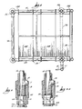
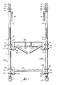
- FIGURE 7 shows a side elevational view of the completed scaffold platform module.
- FIGURE 8 shows a plan view of the module in FIGURE 7 but in FIGURE 8 one guard rail section has been attached as will be discussed in greater detail shortly hereinafter.
- FIGURES 6-8 it should be apparent from FIGURES 6-8 that when the first module is complete, there is a place for workers to stand to build out additional modules and a continuous platform in any direction.
- a so called swing platform could be suspended from the lower eye nuts on the posts of an upper level platform to provide two tiers.
- FIGURE 8 for example, one may see that it is now easy to assemble additional modules to provide a much larger area suspension platform.
- At the corners of the first completed module there are the adjustable posts with the two pairs of rings 26, 27 and 28, 29 on them. None of the rings has any more than two joint devices 35 fastened to it. The two that are fastened to any of the rings are spaced apart by 90° around the axis of the adjustable post. However, there is space around the posts for fastening additional joint devices at least every 45° for the purpose of constructing scaffold and platform extensions of various shapes from any side of the first module that is completed.
- Another method of installing the suspended scaffolding is to assemble a first complete module at ground or floor level and then hoisting the module to the desired elevation in free space above. Additional modules can be constructed and hoisted to the level of the first one and attached to it by workers standing on a previously elevated module. Also, the first elevated module can be used as a platform by workers to assemble and join additional modules, not on the ground, but in the air.
- the guard rail bracket generally designated by the numeral 65, is mounted to an adjustable post outer tubular member 10 in the customary manner using the upper pair of rings 26, 27 and the lower pair 28, 29.
- the guard rail bracket comprises a tubular post 66 which is welded at its bottom end 67 to an angular member 68 which is reinforced with a gusset plate 69.
- Angular member 68 is welded onto a joint device 35.
- the joint device is shown secured already by reason of wedge 36 having been driven home to lock the joint device 35 onto the lower rings 28, 29 of the post 10.
- the bracket is provided with coupling pin 70 which can telescope into tube 66 of the guard rail bracket assembly.
- coupling pin 70 can telescope into tube 66 of the guard rail bracket assembly.
- a guard rail post 77 is telescoped over tube 66.
- the upper end of telescoping member 70 is provided with a hole 72 for anchoring the guard rail post to the guard rail bracket.
- Horizontal tubes 78 and 79 such as those shown in hidden lines in FIGURE 9 and those 80 and 81, shown in FIGURE 8, are then used as horizontal guard rails attached to the vertical posts.
- FIGURE 9 the joint devices for attaching rails 78 and 79 to the guard rail post are not shown but FIGURE 8 illustrates how the rails are attached.
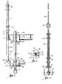
- FIGURES 10 and 11 show an alternative embodiment of the new adjustable post based on principles disclosed in the previously discussed embodiment.
- the FIGURE 10 embodiment comprises an outer tube 90 which has what is called an inverted nut 91 fastened to its lower end by any suitable means such as welding.
- the nut has an internally threaded bore 92.
- a long tubular member 93 having an external thread screws into the threaded hole 92 of nut 91.
- Externally threaded tubular member 93 has a pair of handles 94 at its upper end for turning it in threaded hole 92.
- a load bearing member such as a wire rope extends through the axial length of externally threaded internal tube 93.
- wire rope 95 is anchored in the top of a building or boiler or wherever the adjustable post of FIGURE 10 will be used to assemble a platform that is adapted for being suspended off the ground or floor.
- a rod or chain or other elongated member could be used in place of wire rope 95 for supporting the load.
- wire rope 95 terminates at its lower end in a stop member 96 that is suitably fastened, such as by swaging it to the table.
- a washer 97 having a lateral slot 98 is supported on the fitting or stop member 96.
- a bolt 100 retains the washer on the wire rope.
- External tube 90 is provided with upper and lower annular rings 102 and 103 which provide one way for attaching runners as in the previously described embodiment. It should be understood, however, that the principles of the adjustable post depicted in FIGURE 10 can be fulfilled by means other than pairs of rings 102 and 103 are used to attach runners and trusses. There are well known commercially available clamps that facilitate connecting a runner, for example, at right angles to a vertical tube such as outer tube 90.
- the outer tube 90 supports the weight of the scaffolding platform.
- the elevation of attachment rings 102 for example, relative to the wire rope, determine the elevation of the scaffolding platform structure.
- handles 94 are used to turn the externally threaded inner tube 93 in one direction or the other.
- Tube 93 in effect, is applying a force to wire rope 95 through the agency of slotted washer 97, stop fitting or stop member 96 and washers 101. Since external tube 90 is held against rotation, it and the platform structure attached to it will raise and lower relative to wire rope 95 depending on the direction of rotation in which externally threaded inner tube 93 is turned.
Landscapes
- Engineering & Computer Science (AREA)
- Architecture (AREA)
- Mechanical Engineering (AREA)
- Civil Engineering (AREA)
- Structural Engineering (AREA)
- Movable Scaffolding (AREA)
- Mutual Connection Of Rods And Tubes (AREA)
Claims (8)
- Module de plate-forme pour échafaudage volant suspendu, comportant :
une pluralité de montants (39A à 39D) disposés verticalement prévus pour être connectés à des moyens de suspension (40-43) tels qu'un câble métallique, des chaînes, des tiges ou autres, lesdits montants (39A à 39D) étant disposés de façon correspondante en parallèle pour définir la forme d'une structure support de plate-forme,
des éléments d'entretoises courantes allongées (48-51) reliant lesdits montants (39A à 39D) depuis un montant jusqu'au montant suivant et des moyens de jonction pour connecter les extrémités desdits éléments d'entretoises courantes auxdits montants,
un premier élément d'armature (60) relient deux desdits montants et un deuxième élément d'armature (59) reliant entre eux deux autres desdits montants en parallèle avec le premier élément d'armature et des moyens de jonction pour connecter lesdits éléments d'armature auxdits montants,
des planches (55) dont les extrémités sont supportées par les éléments d'armature (59, 60) pour constituer une plate-forme, et
des moyens pour connecter et positionner les montants (39A à 39D) par rapport auxdits moyens de suspension (40-43)
caractérisé en ce que
lesdits montants (39A à 39D) comportent
un élément tubulaire extérieur (10) prévu pour être connecté auxdits éléments d'entretoises courantes (48-51) et auxdits éléments d'armature (59-60) comportant un élément taraudé (12) fixé coaxialement audit élément tubulaire extérieur (10) au voisinage d'une desdites extrémités,
un élément tubulaire intérieur fileté extérieurement (13) prévu pour être vissé audit élément (12) concentrique audit élément tubulaire extérieur (10) et
un élément allongé (14) s'étendant à travers ledit élément tubulaire intérieur (13) et comportant un moyen d'arrêt (21, 22, 23) fixés audit élément allongé (14) au-delà des extrémités inférieures nominales desdits éléments tubulaires intérieurs et extérieurs, ledit élément allongé étant connecté auxdits moyens de suspension,
lesdits éléments tubulaires intérieurs pouvant être tournés à l'intérieur dudit élément tubulaire extérieur entraînant ainsi un mouvement de réglage de l'élément tubulaire extérieur (10) par rapport aux moyens de suspension (40-43). - Module de plate-forme selon la revendication 1, dans lequel :
ledit élément allongé est une tige métallique (14) qui s'étend à travers lesdits éléments tubulaires intérieur et extérieur (13, 10) et ledit moyen d'arrêt (21, 22, 23), et qui est fixé à ladite tige (14),
ladite tige comportant une extrémité filetée au voisinage de ladite extrémité supérieure nominale dudit élément tubulaire intérieur fileté et un moyen d'écrou à oeillet (15) vissé à ladite extrémité filetée pour faciliter la suspension dudit montant (39A à 39D). - Module de plate-forme selon la revendication 2, dans lequel ladite tige (14) comporte une extrémité filetée au voisinage de ladite extrémité inférieure nominale dudit élément tubulaire intérieur fileté (13) et un moyen d'écrou à oeillet (21, 22, 23) vissé sur ladite extrémité filetée, et constituant ledit moyen d'arrêt.
- Module de plate-forme selon la revendication 1, dans lequel ledit élément allongé est un câble métallique (95) qui s'étend à travers lesdits éléments tubulaires intérieur et extérieur (93, 90) et où ledit moyen d'arrêt est fixé audit câble métallique.
- Module de plate-forme selon l'une quelconque des revendications 1 à 4, comportant une manette (94, 19) fixée audit élément tubulaire intérieur fileté extérieurement (13, 93) pour faciliter la rotation dudit élément.
- Module de plate-forme selon la revendication 5, dans lequel ladite manette (19) est connectée pivotante audit élément tubulaire intérieur (13).
- Module de plate-forme selon l'une quelconque des revendications 1 à 6, comportant des moyens d'attache (26, 27) fixés à l'extérieur dudit élément tubulaire extérieur (10) pour faciliter l'attache des éléments de structure de plate-forme.
- Module de plate-forme selon la revendication 7, dans lequel lesdits moyens d'attache sont constitués par une paire de bagues séparées dans une direction axiale (26, 27) fixées coaxialement audit élément tubulaire extérieur (10) au voisinage d'une extrémité dudit élément comportant ledit taraudage, et une autre paire de bagues séparées dans une direction axiale fixées coaxialement audit élément tubulaire extérieur au voisinage de l'extrémité opposée dudit élément.
Applications Claiming Priority (2)
| Application Number | Priority Date | Filing Date | Title |
|---|---|---|---|
| US169825 | 1980-07-17 | ||
| US07/169,825 US4815563A (en) | 1988-03-17 | 1988-03-17 | Adjustable post and method of using the post to erect suspension scaffolding |
Publications (3)
| Publication Number | Publication Date |
|---|---|
| EP0332748A2 EP0332748A2 (fr) | 1989-09-20 |
| EP0332748A3 EP0332748A3 (en) | 1990-05-16 |
| EP0332748B1 true EP0332748B1 (fr) | 1992-05-20 |
Family
ID=22617332
Family Applications (1)
| Application Number | Title | Priority Date | Filing Date |
|---|---|---|---|
| EP88118687A Expired EP0332748B1 (fr) | 1988-03-17 | 1988-11-09 | Plateforme modulaire pour échafaudage volant |
Country Status (3)
| Country | Link |
|---|---|
| US (1) | US4815563A (fr) |
| EP (1) | EP0332748B1 (fr) |
| DE (1) | DE3871370D1 (fr) |
Families Citing this family (30)
| Publication number | Priority date | Publication date | Assignee | Title |
|---|---|---|---|---|
| US6286691B1 (en) * | 1997-07-14 | 2001-09-11 | Industrial Wire Products, Inc. | Shelving for suspension from rafters, or the like |
| US6098751A (en) * | 1998-09-10 | 2000-08-08 | Mountain Box Systems | Studio lamp scaffold system |
| US5954155A (en) * | 1999-01-25 | 1999-09-21 | Panageotes; Peter | Bridge containment system |
| US6264001B1 (en) * | 2000-01-04 | 2001-07-24 | Robert Herschbach | Scaffolding hanger |
| ES2196977B1 (es) * | 2001-10-26 | 2005-03-01 | Saul Diez Valbuena | Sistema de andamiaje suspendido estatico-multiple. |
| US20070210025A1 (en) * | 2002-10-07 | 2007-09-13 | Oberhaus Fred D | Componentry assembled free standing wire rack |
| US7980523B2 (en) * | 2003-04-03 | 2011-07-19 | Securus, Inc. | Suspended platform for water heaters |
| US7779599B2 (en) * | 2004-03-31 | 2010-08-24 | Safway Services, Llc | Articulating work platform support system, work platform system, and methods of use thereof |
| US7857097B2 (en) * | 2004-11-10 | 2010-12-28 | Patrick Evinger | Scaffolding apparatus and method |
| CA2498870C (fr) * | 2004-12-17 | 2006-01-24 | Structure D'acier Orleans Inc. | Echafaudage volant a cables |
| US20060157435A1 (en) * | 2005-01-05 | 2006-07-20 | Oberhaus Fred D | Componentry assembled free standing wire shelving and organizer |
| US20060225955A1 (en) * | 2005-04-11 | 2006-10-12 | Murphy Daniel G | Breakdown self propelled elevating work platform |
| JP4154534B2 (ja) * | 2005-09-20 | 2008-09-24 | 株式会社日立プラントテクノロジー | ボイラ用大型部品の点検用足場構築方法 |
| US20090222998A1 (en) * | 2008-03-05 | 2009-09-10 | Ruggles Mark D | Combination hammer and nail driver |
| US8123001B1 (en) | 2008-03-18 | 2012-02-28 | Paul Kristen, Inc. | Modular platform/ scaffolding |
| USD616570S1 (en) * | 2009-06-08 | 2010-05-25 | Dezi Krajcir | Scaffold ledger |
| EP2298998B1 (fr) * | 2009-09-18 | 2020-04-29 | Paul Kristen, Inc. | Connecteur de câble et panneau à utiliser pour des plateformes de pont et autres échafaudages |
| CN101672102B (zh) * | 2009-10-19 | 2015-03-04 | 中铁建设集团有限公司 | 钢结构高空吊顶施工平台 |
| US20120155970A1 (en) * | 2010-12-15 | 2012-06-21 | Fci Holdings Delaware, Inc. | Mine Roof Bolt With End Fitting |
| US9784001B1 (en) * | 2011-05-03 | 2017-10-10 | Paul Kristen, Inc | Adjustable scaffolding suspension assembly |
| USD663438S1 (en) * | 2011-12-06 | 2012-07-10 | Urban Umbrella Enterprises, LLC | Umbrella scaffolding structure |
| MX354018B (es) * | 2012-02-08 | 2018-02-08 | Safway Services Llc | Sistema de conector de suspensión configurado para su uso con andamios suspendidos y métodos relacionados. |
| JP6420755B2 (ja) * | 2015-12-28 | 2018-11-07 | 株式会社国元商会 | チエン長さ調節金具 |
| JP2018044392A (ja) * | 2016-09-15 | 2018-03-22 | サンオー産業株式会社 | 長さ調整具 |
| CN108423534A (zh) * | 2017-02-14 | 2018-08-21 | 江西昌河航空工业有限公司 | 一种汽车吊装工具及其方法 |
| US10738423B1 (en) * | 2018-11-26 | 2020-08-11 | Paul Kristen, Inc. | Platform and the hanging thereof from a bridge main cable |
| US11002026B1 (en) * | 2020-03-06 | 2021-05-11 | Paul Kristen, Inc. | Adjustable suspension assembly |
| CN112942895B (zh) * | 2021-01-30 | 2022-04-15 | 山东工程职业技术大学 | 一种可调节的v型钢支撑安装施工结构 |
| WO2025251137A1 (fr) * | 2024-06-07 | 2025-12-11 | 3L-Innogénie Inc. | Plate-forme de travail mobile et procédé associé pour fournir un accès à un extérieur d'un bâtiment existant à plisieurs étages |
| CN120656818B (zh) * | 2025-06-25 | 2025-11-28 | 北京海泉电力安装有限公司 | 一种变压器安装辅助悬挂装置及方法 |
Family Cites Families (13)
| Publication number | Priority date | Publication date | Assignee | Title |
|---|---|---|---|---|
| US1153884A (en) * | 1915-06-02 | 1915-09-21 | Heinrich Bade Jr | Scaffold. |
| US1725183A (en) * | 1926-08-23 | 1929-08-20 | Anthony C Fischer | Scaffold-suspension device |
| US1663131A (en) * | 1927-02-24 | 1928-03-20 | American Safety Device Company | Scaffold |
| US2592315A (en) * | 1948-09-30 | 1952-04-08 | Mosley Clifton Evans | Universal electric fixture hanger |
| US3394776A (en) * | 1967-03-22 | 1968-07-30 | Wye Delta Equipment Corp | Suspended traveling scaffold |
| US3420332A (en) * | 1967-07-14 | 1969-01-07 | Richard A Textor | Elevator for quick assemblage and use in limited access enclosures |
| US3524520A (en) * | 1968-08-29 | 1970-08-18 | Paul J Tidwell | Traveling scaffold |
| BE750545A (nl) * | 1970-05-19 | 1970-11-03 | Sky Climber Inc | Platform voor hangstellingen en dergelijke, |
| US3700071A (en) * | 1971-07-03 | 1972-10-24 | Reizo Kikuchi | Method of erecting suspended scaffolding at construction field and scaffolding erected thereby |
| US3851729A (en) * | 1973-10-04 | 1974-12-03 | Gordon Arnold | Scaffold structure |
| SU709781A1 (ru) * | 1978-01-05 | 1980-01-15 | Восточный Филиал Проектно-Технологического Института "Энергомонтажпроект" | Подвесные леса |
| US4163480A (en) * | 1978-02-21 | 1979-08-07 | Highland Stanley E | Line travelling skips |
| US4413707A (en) * | 1981-05-28 | 1983-11-08 | Swiss Fabricating, Inc. | Suspended chain scaffolding employing adjustable posts with chain threaded therethrough |
-
1988
- 1988-03-17 US US07/169,825 patent/US4815563A/en not_active Expired - Lifetime
- 1988-11-09 DE DE8888118687T patent/DE3871370D1/de not_active Expired - Fee Related
- 1988-11-09 EP EP88118687A patent/EP0332748B1/fr not_active Expired
Also Published As
| Publication number | Publication date |
|---|---|
| DE3871370D1 (de) | 1992-06-25 |
| EP0332748A2 (fr) | 1989-09-20 |
| US4815563A (en) | 1989-03-28 |
| EP0332748A3 (en) | 1990-05-16 |
Similar Documents
| Publication | Publication Date | Title |
|---|---|---|
| US4815563A (en) | Adjustable post and method of using the post to erect suspension scaffolding | |
| AU2010346421B2 (en) | Scaffold and methods for installing or removing such a scaffold | |
| CA1323393C (fr) | Systeme d'echafaudage modulaire et joints de raccordement connexes | |
| EP2354375A1 (fr) | Système d'échafaudage | |
| CN101341306B (zh) | 应用于建筑的安全系统 | |
| US2201608A (en) | Scaffolding | |
| CA2498870C (fr) | Echafaudage volant a cables | |
| CN111852074B (zh) | 一种可调节升降式支撑装置 | |
| US2883241A (en) | Scaffolding accessory | |
| JPH06323503A (ja) | 大型吊下げ式ボイラの組立方法 | |
| CN212053667U (zh) | 便于安装的建筑物外墙施工脚手架 | |
| JP2986430B2 (ja) | 建築物を構築するための吊り足場用金具及び吊り足場 | |
| KR900008874B1 (ko) | 고소작업용 족장 및 그의 시설공법 | |
| JP2506464B2 (ja) | 工業化住宅の屋根作業用柵 | |
| US5012894A (en) | Scaffold erection structure | |
| CN222949421U (zh) | 一种用于圆形结构的楼梯塔架系统 | |
| JPH01322064A (ja) | 足場用鋼管を用いて一括上架仮設を行なう建設工事用足場架設工法 | |
| JPH0443141B2 (fr) | ||
| JP2020007738A (ja) | 支柱支持具 | |
| SU705092A1 (ru) | Устройство дл производства монтажных и строительных работ | |
| JPH07102788A (ja) | 仮設用安全手摺り | |
| JPH0530949B2 (fr) | ||
| GB2169641A (en) | An erection aid for scaffolding | |
| JP3106270B2 (ja) | 構造物の吊上げ・接合用の柱及び構造物の吊上げ方法 | |
| JPS641395Y2 (fr) |
Legal Events
| Date | Code | Title | Description |
|---|---|---|---|
| PUAI | Public reference made under article 153(3) epc to a published international application that has entered the european phase |
Free format text: ORIGINAL CODE: 0009012 |
|
| AK | Designated contracting states |
Kind code of ref document: A2 Designated state(s): BE DE FR GB IT |
|
| PUAL | Search report despatched |
Free format text: ORIGINAL CODE: 0009013 |
|
| AK | Designated contracting states |
Kind code of ref document: A3 Designated state(s): BE DE FR GB IT |
|
| 17P | Request for examination filed |
Effective date: 19900711 |
|
| 17Q | First examination report despatched |
Effective date: 19910117 |
|
| ITF | It: translation for a ep patent filed | ||
| GRAA | (expected) grant |
Free format text: ORIGINAL CODE: 0009210 |
|
| AK | Designated contracting states |
Kind code of ref document: B1 Designated state(s): BE DE FR GB IT |
|
| REF | Corresponds to: |
Ref document number: 3871370 Country of ref document: DE Date of ref document: 19920625 |
|
| ET | Fr: translation filed | ||
| PGFP | Annual fee paid to national office [announced via postgrant information from national office to epo] |
Ref country code: GB Payment date: 19921102 Year of fee payment: 5 |
|
| PGFP | Annual fee paid to national office [announced via postgrant information from national office to epo] |
Ref country code: FR Payment date: 19921109 Year of fee payment: 5 |
|
| PG25 | Lapsed in a contracting state [announced via postgrant information from national office to epo] |
Ref country code: BE Effective date: 19921130 |
|
| PLBE | No opposition filed within time limit |
Free format text: ORIGINAL CODE: 0009261 |
|
| STAA | Information on the status of an ep patent application or granted ep patent |
Free format text: STATUS: NO OPPOSITION FILED WITHIN TIME LIMIT |
|
| 26N | No opposition filed | ||
| BERE | Be: lapsed |
Owner name: FIGGIE INTERNATIONAL INC. Effective date: 19921130 |
|
| PG25 | Lapsed in a contracting state [announced via postgrant information from national office to epo] |
Ref country code: DE Effective date: 19930803 |
|
| PG25 | Lapsed in a contracting state [announced via postgrant information from national office to epo] |
Ref country code: GB Effective date: 19931109 |
|
| GBPC | Gb: european patent ceased through non-payment of renewal fee |
Effective date: 19931109 |
|
| PG25 | Lapsed in a contracting state [announced via postgrant information from national office to epo] |
Ref country code: FR Effective date: 19940729 |
|
| REG | Reference to a national code |
Ref country code: FR Ref legal event code: ST |
|
| PG25 | Lapsed in a contracting state [announced via postgrant information from national office to epo] |
Ref country code: IT Free format text: LAPSE BECAUSE OF NON-PAYMENT OF DUE FEES;WARNING: LAPSES OF ITALIAN PATENTS WITH EFFECTIVE DATE BEFORE 2007 MAY HAVE OCCURRED AT ANY TIME BEFORE 2007. THE CORRECT EFFECTIVE DATE MAY BE DIFFERENT FROM THE ONE RECORDED. Effective date: 20051109 |