EP0332769A1 - Vorrichtung zum Überwachen von Kraftfahrzeug-Wartungsintervallen - Google Patents
Vorrichtung zum Überwachen von Kraftfahrzeug-Wartungsintervallen Download PDFInfo
- Publication number
- EP0332769A1 EP0332769A1 EP88302190A EP88302190A EP0332769A1 EP 0332769 A1 EP0332769 A1 EP 0332769A1 EP 88302190 A EP88302190 A EP 88302190A EP 88302190 A EP88302190 A EP 88302190A EP 0332769 A1 EP0332769 A1 EP 0332769A1
- Authority
- EP
- European Patent Office
- Prior art keywords
- vehicle
- monitor
- maintenance
- estimated
- intervals
- Prior art date
- Legal status (The legal status is an assumption and is not a legal conclusion. Google has not performed a legal analysis and makes no representation as to the accuracy of the status listed.)
- Withdrawn
Links
- 238000012423 maintenance Methods 0.000 title claims abstract description 64
- 238000000034 method Methods 0.000 claims description 5
- 238000012544 monitoring process Methods 0.000 claims description 2
- 230000000007 visual effect Effects 0.000 claims 1
- 230000000994 depressogenic effect Effects 0.000 description 9
- 238000004364 calculation method Methods 0.000 description 7
- 230000006870 function Effects 0.000 description 6
- 125000004122 cyclic group Chemical class 0.000 description 3
- 239000011159 matrix material Substances 0.000 description 3
- 230000008439 repair process Effects 0.000 description 3
- 238000010586 diagram Methods 0.000 description 2
- 230000033228 biological regulation Effects 0.000 description 1
- 230000005540 biological transmission Effects 0.000 description 1
- 238000004590 computer program Methods 0.000 description 1
- 239000004020 conductor Substances 0.000 description 1
- 238000012790 confirmation Methods 0.000 description 1
- 238000010276 construction Methods 0.000 description 1
- 230000001186 cumulative effect Effects 0.000 description 1
- 238000013479 data entry Methods 0.000 description 1
- 238000013500 data storage Methods 0.000 description 1
- 230000003111 delayed effect Effects 0.000 description 1
- 239000012530 fluid Substances 0.000 description 1
- 238000009434 installation Methods 0.000 description 1
- 230000001788 irregular Effects 0.000 description 1
- 239000004973 liquid crystal related substance Substances 0.000 description 1
- 230000007774 longterm Effects 0.000 description 1
- 239000000463 material Substances 0.000 description 1
- 238000012545 processing Methods 0.000 description 1
- 230000001681 protective effect Effects 0.000 description 1
- 238000012552 review Methods 0.000 description 1
- 230000001629 suppression Effects 0.000 description 1
- 230000001052 transient effect Effects 0.000 description 1
Images


Classifications
-
- G—PHYSICS
- G07—CHECKING-DEVICES
- G07C—TIME OR ATTENDANCE REGISTERS; REGISTERING OR INDICATING THE WORKING OF MACHINES; GENERATING RANDOM NUMBERS; VOTING OR LOTTERY APPARATUS; ARRANGEMENTS, SYSTEMS OR APPARATUS FOR CHECKING NOT PROVIDED FOR ELSEWHERE
- G07C5/00—Registering or indicating the working of vehicles
- G07C5/006—Indicating maintenance
Definitions
- the invention relates to maintenance interval monitors, especially those designed for use with motor vehicles.
- maintenance intervals vary depending upon the vehicle's actual use. For example, oil must be changed frequently when the vehicle is used only for short trips, while more miles are acceptable between oil changes if the vehicle is used only for long distance, highway driving. This variability of usage further complicates the problem of vehicle maintenance, because generally manufacturer maintenance recommendations are for only a single mileage value, thereby creating many non-optimal maintenance situations. For these reasons, a number of types of maintenance interval monitors have been proposed.
- U.S. Patent No. 4,031,363 involved an electronic monitor which indicated the need for vehicle maintenance after a fixed time interval or after a fixed distance interval. The distance traveled was determined from the speedometer cable or other mileage sensor. The monitor did not allow the intervals to be changed by the vehicle owner.
- U.S. Patent No. 4,159,531 related to an electronic service indication system. When queried, the system indicated the next mileage at which maintenance should be performed and the names of the tasks to be performed. The suggested mileages between tasks was not alterable by the user and here was no prompting to indicate when service was to be performed. The system also allowed storage of the actual mileages at which service was performed by the proper facility, but required special equipment to record the values.
- U.S. Patent No. 4,404,641 disclosed an electronic equipment maintenance monitor which compared elapsed running time with owner selectable time values to enable warning indicators and equipment disabling devices.
- the monitor should be very easy to install in a vehicle. This eliminates the devices requiring elaborate electrical connections or connections to the vehicle speedometer cable. Some object to connecting other meters than the speedometer to the speedometer cable.
- the monitor should use miles for the service interval because mileage is the common standard used to determine maintenance requirements. This eliminates the devices which only measure elapsed time.
- the monitor should allow the owner to individually select or vary maintenance intervals, to allow for individual vehicle use differences. This eliminates any devices which have maintenance intervals settable only by the manufacturer.
- the present invention provides a new and improved programmable motor vehicle maintenance interval monitor.
- the monitor is computer-based and the only connection to the vehicle required are to the battery and the ignition circuit.
- the monitor displays six maintenance items and the mileage remaining until each item needs service.
- a display on the monitor shows the date and time.
- a warning device such as a beeper, sounds indicating the need to service that maintenance item.
- the owner enters the desired number of miles before that item is to be next serviced. Additionally, the owner can change the remaining mileage in any category at any time to allow for changes in vehicle use or provide for early maintenance.
- the elapsed mileage the vehicle has traveled is calculated from the running time of the vehicle.
- the monitor determines the elapsed time the vehicle has been running since the last mileage calculation was performed and multiplies this time by a speed factor to estimate the distance traveled since the last mileage calculation.
- the mileage calculations are done on a frequent basis to minimize starting and ending errors.
- the speed factor can be changed by the owner to better match individual driving conditions.
- a monitor module M (Fig. 1), which includes an interface unit I and a computer C is shown electrically connected to a battery 20 of a vehicle V.
- the monitor module M of the present invention allows an operator of the vehicle or maintenance personnel to determine when any of a selected number of maintenance items or tasks are to be performed.
- the monitor module M of the present inventions permits a number, in the preferred embodiment six, of maintenance items with the same or different intervals to be separately monitored. Further, the individual intervals may be selectively varied as vehicle usage needs or experience vary.
- the vehicle battery 20 is electrically connected to an ignition switch 22. The remaining portions of the vehicle electrical system are conventional and for this reason not shown.
- a protective full wave rectifier diode bridge 24 is connected to the battery 20 to prevent any damage to the monitor M should either the vehicle battery 20 leads or monitor connections be reversed.
- the output leads of the bridge 24 are connected to a series connected current limiting resistor 26, a first battery 28 and a second battery series 30.
- the battery series 30 provides operating direct current power at the requisite voltage level to the computer C (Fig. 2) employed in the monitor M.
- the first battery 28 raises the overall voltage present at one input to resistor 26 to a greater level, preferably that of vehicle battery 20, to reduce the power dissipated in the current limit resistor 26, thereby extending vehicle battery life and reducing current drain.
- the first battery 28 and the second battery series 30 perform the additional functions of voltage regulation and transient suppression to protect the computer C from undervoltage conditions during vehicle starting, overvoltage conditions due to vehicle electrical system failure and other transients present in the vehicle electrical system.
- a bias resistor 32 and a relay 34 of the interface I are electrically connected to the vehicle ignition switch 22.
- the bias resistor 32 is used to provide the proper operating voltage or current to a coil 35 of relay 34.
- the relay 34 also has a single pole, normally-closed contact 36 which is connected over conductors 38 and 40 to the computer C. Because the contact 36 is normally-closed, when the vehicle ignition is off the contact 36 is closed, while when the ignition is on the contact 36 is open. In this manner the monitor M determines when the vehicle is running.
- a central processor unit 50 having an address bus 52 and a data bus 54 is connected to random access memory 58; read-only memory 56; a display 62, through a display driver 60; and an input/output section 63.
- the input/output section 63 has an input/output controller 64 connected to a timer 66, a beeper or other suitable alarm 67 and a keyboard matrix 68.
- the timer 66 contains a free running timer which functions as a computer real time clock for the computer C.
- the processor 50 accesses the timer 66 to determine the day, hour, minute and second of the current time to allow the computer C to keep track of elapsed time.
- Keyboard matrix 68 may be any of several commercially available computer data entry keyboards.
- the leads 38 and 40 from the relay contact 36 are connected to the keyboard matrix 68 across a suitable key, such as a parenthesis key.
- a parenthesis key When the ignition is off, the parenthesis key appears electrically to be depressed because contact 36 is in its normally closed state.
- the keyboard 68 is used to enter the new mileage intervals for the various items stored in the monitor and query the monitor for the date and time and particular item mileage values.
- the display 62 shows the vehicle operator or maintenance personnel, the date and time when the vehicle is not running. When the vehicle ignition switch 22 is closed the display 62 shows the mileage remaining before servicing of the various stored items.
- the display 62 allows confirmation of the keyboard buttons pressed while entering new information because the information for processor 50 obtained through input/output unit 64 is also presented on data bus 54 to display driver 60.
- the display 62 is preferably a liquid crystal display to preserve battery life and reduce system power requirements.
- the alarm 67 is accessible to the central processing unit 50 of computer C through input/output unit 64. In the preferred embodiment, the alarm 67 is a beeper which provides an audible warning when the established interval for a maintenance item has elapsed.
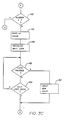
- the computer & operates on a stored series of control instructions in the form of a computer program, the steps of which are shown schematically in Figs. 3A, 3B, 3C and 4.
- an initialization sequence 100 (Fig. 3A) is performed to clear all data storage registers.
- the first step of the sequence is step 102, where an alarm flag is set to indicate that the alarm function is enabled.
- Step 104 then prepares the various item descriptors and initial values used in connection with the various maintenance items.
- the descriptors are the names of the maintenance items to be monitored, and are displayed in conjunction with the item's mileage value during monitor operation to ease owner understanding of the displayed information.
- the maintenance items to be monitored in the preferred embodiment are oil change, tire rotation, spark plug change, transmission fluid change, belt replacement, and brake maintenance.
- the descriptors and maintenance interval values in miles are accordingly OIL, 2000; ROTATE, 7000; PLUGS, 10000; TRANS, 20000; BELTS, 25000; and BRAKES, 35000.
- a seventh item initialized is a speed factor, referred to as SPEED with a value of 45.0 mph. This value is used in conjunction with the elapsed time to determine the estimated miles the vehicle has traveled. After completing the initialization in step 104, control is transferred to the main program sequence 110.
- the main program sequence 110 is the main control loop of the program.
- the sequence 110 commences at step 112 where the current time is determined by reading the timer 66.
- Step 114 follows and the old time is made equal to the current time. This is done so that errors do not occur because of a randomly generated initial old time.
- step 116 determines the current time so that two times are available for calculation purposes.
- Step 118 computes the elapsed time by subtracting the old time from the new time. This value is then used in step 120 where it is multiplied by the speed factor to determine an estimated distance traveled during the elapsed interval.
- the estimated mileage may be incorrect for any single interval, but by properly choosing the speed factor, the errors average out over a longer period of time and the total miles traveled as indicated by this indirect method is sufficiently close to the actual miles traveled.
- Step 121 sets a pointer to indicate the first of the six maintenance items.
- Step 122 then subtracts the estimated distance from the remaining mileage value of the item indicated by the pointer. This decrements the mileage value from either the initially preset value or the owner entered value so that when the value reaches zero or becomes negative, service is due on that item.
- the item is displayed in step 124 by using the display value subroutine 200 (Fig. 4).
- Step 126 determines if a valid character on the keyboard has been pressed. In the preferred embodiment, valid characters at this step are any non-control characters. If a valid character has not been pressed, control proceeds to step 127 where the pointer is incremented to point to the next maintenance item. Following this, step 128 (Fig. 3B) determines if the last item has been completed. Only the six maintenance items are displayed in this cyclic manner. The seventh item, the speed factor, is not displayed at this time because it is a constant and is not an item requiring servicing.
- step 128 determines that the last item has not been updated and displayed, control transfers to step 122 and the next item is processed. If the final item has been displayed, control transfers to step 130 where the current time is renamed to be the old time and control transfers to step 116 (Fig. 3A) to begin a new calculation cycle.
- the average time for a calculation cycle in the preferred embodiment of six maintenance items is approximately 9 seconds, each item display taking approximately 11 ⁇ 2 seconds.
- step 126 determines that a valid character has been depressed, control transfers to step 132 (Fig. 3B).
- Step 132 determines if a number was pressed. If a number key was not depressed, step 134 displays the date and time. In this way the normal cyclic item display can be temporarily halted and the monitor used as a clock. After displaying the date and time in step 134, control proceeds to step 136 where the date and time are again displayed.
- step 138 determines whether the key that was depressed was the parenthesis key connected to relay contact 36. If so, control proceeds to step 136 for a redisplay of the date and time. Because the relay contact 36 is connected to the parenthesis key, anytime the vehicle ignition is off, the monitor M stays in this loop and the date and time are continuously displayed.
- step 140 sets the alarm flag to enable the warning and indication function. This causes the alarm 67 to be activated every time the vehicle is started, because this portion of the program is performed every time the vehicle is started. This also sets the alarm flag if the date display is requested while the vehicle ignition is on, allowing the owner to enable the warning function after vehicle starting. After setting the alarm flag, control is passed to step 112 to restart the main sequence 110.
- step 132 determines that a number key had been depressed
- step 142 determines that the number was seven or less control is transferred to the display value subroutine 200 by step 144 and the item corresponding to the depressed number is displayed. This path is used to examine and optionally change the remaining mileage value of a particular maintenance item or the speed factor value.
- step 146 determines if a carriage return has been entered on the keyboard. If not, control passes to step 150 which determines whether the wait loop has finished. If not, control proceeds to step 148, forming a loop. This loop allows the owner a period of time to determine if this is the proper item to be changed and so indicate by pressing the carriage return key. If the wait loop is finished, control proceeds to step 116, allowing the program to continue if the wrong item had been selected.
- step 152 allows the new value for the selected maintenance item to be entered from the keyboard 68 and displayed on the display 62. After the new value is entered, control returns to step 116 of the main loop (Fig. 3A).
- the owner can change any of the values as desired and when desired.
- This allows new intervals to be reset after the maintenance has been performed and allows the owner to set the service intervals at individually desired mileages, not mileages suggested by the manufacturer.
- This enables the vehicle operator or maintenance personnel to better match the service intervals with their preferences and driving style and habits.
- This adaptable feature also allows a change in the mileage factor to better suit the operator's driving routine. If the trips are generally short trips done on heavily congested traffic, the speed factor should be lower to correspond to the slower average speeds and the service intervals should be shorter to correspond to the higher stress on the vehicle components. Conversely, if the vehicle is generally used for long trips on the open highway, a higher speed factor and longer mileage intervals can be used to reflect the higher average speed and lower vehicle stress. The present monitor allows these individual variations to be handled quite easily.
- the values can be altered only when the vehicle ignition is on because when the vehicle is off, the monitor only displays the date and time because the parenthesis key connected to contact 36 is always electrically sensed as being depressed.
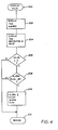
- the display value subroutine 200 (Fig. 4) performs the tasks of displaying the values for a given item and sounding the alarm 67 as appropriate.
- the first step in the subroutine after entry is step 202 where the item's number is displayed for a period of time. This is done to allow correlation between the item's numerical and descriptor representations.
- step 204 displays the maintenance item descriptor and the remaining mileage value for that item.
- step 206 determines if the value is less than zero, which indicates that the item should be serviced. If this is the case, control proceeds to step 208 which determines if the alarm flag is set. If so, step 210 activates the alarm for a period of time to alert the owner and then clears the alarm flag. This clearing is done because it is desired that the alarm be active only after the car is started or after the date and time have been requested and not every time the particular item is displayed. After clearing the flag, control proceeds to step 212, the return to the routine 100.
- each maintenance item during the cyclic display operation period. If the number of maintenance items exceeds a larger number than six, it may be preferable that not all the items be displayed. This is because viewing the entire series would require a large amount of time and might require that the owner wait a long period to see a particular item of concern, especially those nearing service time. To this end, in an alternate embodiment only the three items closest to the end of their maintenance intervals are displayed. This makes it easier to monitor items nearing service.
- the mileage value for all items is first calculated, with the lowest three being noted during the update calculations. After completing the update, the three noted items are displayed. After displaying the items the computer C then determines If a valid key has been pressed. A review of all the items is obtained by pressing a designated key on the keyboard 68, causing the computer C to perform a different subroutine to display all maintenance items.
- the present monitor is very easy to install and yet is a very flexible system, working quite well under normal conditions.
Landscapes
- Physics & Mathematics (AREA)
- General Physics & Mathematics (AREA)
- Electric Propulsion And Braking For Vehicles (AREA)
- Emergency Alarm Devices (AREA)
Priority Applications (3)
| Application Number | Priority Date | Filing Date | Title |
|---|---|---|---|
| US06/852,233 US4739482A (en) | 1986-04-15 | 1986-04-15 | Motor vehicle maintenance interval monitor |
| EP88302190A EP0332769A1 (de) | 1986-04-15 | 1988-03-14 | Vorrichtung zum Überwachen von Kraftfahrzeug-Wartungsintervallen |
| JP63084208A JPH0237057A (ja) | 1986-04-15 | 1988-04-07 | 車両整備インターバル・モニター及び車両整備インターバルのモニター方法 |
Applications Claiming Priority (3)
| Application Number | Priority Date | Filing Date | Title |
|---|---|---|---|
| US06/852,233 US4739482A (en) | 1986-04-15 | 1986-04-15 | Motor vehicle maintenance interval monitor |
| EP88302190A EP0332769A1 (de) | 1986-04-15 | 1988-03-14 | Vorrichtung zum Überwachen von Kraftfahrzeug-Wartungsintervallen |
| JP63084208A JPH0237057A (ja) | 1986-04-15 | 1988-04-07 | 車両整備インターバル・モニター及び車両整備インターバルのモニター方法 |
Publications (1)
| Publication Number | Publication Date |
|---|---|
| EP0332769A1 true EP0332769A1 (de) | 1989-09-20 |
Family
ID=48795368
Family Applications (1)
| Application Number | Title | Priority Date | Filing Date |
|---|---|---|---|
| EP88302190A Withdrawn EP0332769A1 (de) | 1986-04-15 | 1988-03-14 | Vorrichtung zum Überwachen von Kraftfahrzeug-Wartungsintervallen |
Country Status (3)
| Country | Link |
|---|---|
| US (1) | US4739482A (de) |
| EP (1) | EP0332769A1 (de) |
| JP (1) | JPH0237057A (de) |
Cited By (2)
| Publication number | Priority date | Publication date | Assignee | Title |
|---|---|---|---|---|
| FR2714506A1 (fr) * | 1993-12-28 | 1995-06-30 | Valeo Electronique | Procédé de gestion de la maintenance d'un véhicule, ordinateur de bord et station de diagnostic associés mettant en Óoeuvre le procédé. |
| US6810312B2 (en) * | 2002-09-30 | 2004-10-26 | General Electric Company | Method for identifying a loss of utilization of mobile assets |
Families Citing this family (37)
| Publication number | Priority date | Publication date | Assignee | Title |
|---|---|---|---|---|
| US4739482A (en) * | 1986-04-15 | 1988-04-19 | William Wrigge | Motor vehicle maintenance interval monitor |
| US4862393A (en) * | 1988-01-12 | 1989-08-29 | Cummins Engine Company, Inc. | Oil change interval monitor |
| WO1989007538A1 (fr) * | 1988-02-19 | 1989-08-24 | Kabushiki Kaisha Toyoda Jidoshokki Seisakusho | Dispositif de commande et d'affichage pour vehicule electrique a accumulateurs |
| US4884054A (en) * | 1988-08-18 | 1989-11-28 | Moon Sr John H | Self-contained motor vehicle maintenance interval monitor |
| US5250761A (en) * | 1989-10-02 | 1993-10-05 | Kabushiki Kaisha Komatsu Seisakusho | Managing system for construction vehicles |
| US5553488A (en) * | 1993-07-30 | 1996-09-10 | Toyota Jidosha Kabushiki Kaisha | Diagnosis apparatus for vehicle control system |
| US5642284A (en) * | 1994-08-12 | 1997-06-24 | Caterpillar Inc. | Maintenance monitor system |
| US5548535A (en) * | 1994-11-08 | 1996-08-20 | Advanced Micro Devices, Inc. | Monitor utility for use in manufacturing environment |
| US5819201A (en) * | 1996-09-13 | 1998-10-06 | Magellan Dis, Inc. | Navigation system with vehicle service information |
| US5797107A (en) * | 1996-10-04 | 1998-08-18 | Berg; Eric A. | Equipment utilization detector |
| US5970436A (en) * | 1996-10-04 | 1999-10-19 | Berg; Eric A. | Equipment utilization detector |
| US5750887A (en) * | 1996-11-18 | 1998-05-12 | Caterpillar Inc. | Method for determining a remaining life of engine oil |
| US6681987B1 (en) | 2000-03-09 | 2004-01-27 | Meritor Heavy Vehicle Systems, Llc | Smart card system for heavy vehicles |
| US6363304B1 (en) | 2000-06-12 | 2002-03-26 | Meritor Heavy Vehicle Technology, Llc | Personal data computer for vehicle monitoring |
| US6308120B1 (en) * | 2000-06-29 | 2001-10-23 | U-Haul International, Inc. | Vehicle service status tracking system and method |
| US6516251B1 (en) | 2001-01-23 | 2003-02-04 | Meritor Heavy Vehicle Technology, Llc. | Automated vehicle shutdown sequence |
| US6356824B1 (en) | 2001-01-23 | 2002-03-12 | Meritor Heavy Vehicle Technology, Llc | Vehicle systems data storage |
| US6609082B2 (en) * | 2001-03-22 | 2003-08-19 | David S. Wagner | Machine control device |
| US6587768B2 (en) | 2001-08-08 | 2003-07-01 | Meritor Heavy Vehicle Technology, Llc | Vehicle inspection and maintenance system |
| US6535802B1 (en) | 2002-01-25 | 2003-03-18 | Meritor Heavy Vehicle Technology, Llc | Quick check vehicle diagnostics |
| US7592980B2 (en) * | 2002-06-05 | 2009-09-22 | Semiconductor Energy Laboratory Co., Ltd. | Semiconductor device |
| US20040083040A1 (en) * | 2002-10-28 | 2004-04-29 | Thomas Parrott | Vehicle data retrieval system |
| US7672984B2 (en) | 2003-06-02 | 2010-03-02 | The Cobalt Group, Inc. | Method and system of managing service reminders using mileage estimates |
| US20040243289A1 (en) * | 2003-06-02 | 2004-12-02 | John Kelly | Method and system of managing service reminders using mileage estimates |
| US20050015186A1 (en) * | 2003-06-02 | 2005-01-20 | John Kelly | Method and system of managing service reminders using mileage estimates |
| US7636623B2 (en) * | 2003-06-03 | 2009-12-22 | The Cobalt Group, Inc. | Method and system of managing service reminders and scheduling service appointments using mileage estimates and recommended recall bulletins |
| US7617028B2 (en) * | 2003-06-03 | 2009-11-10 | The Cobalt Group, Inc. | Method and system of managing service reminders and promotions using mileage estimates |
| US7542833B2 (en) | 2003-06-03 | 2009-06-02 | The Cobalt Group, Inc. | Method and system of managing service reminders and scheduling service appointments using mileage estimates |
| US7535347B2 (en) * | 2006-08-16 | 2009-05-19 | International Truck Intellectual Property Company, Llc | Automated synchronized service intervals for vehicles |
| US7589471B2 (en) * | 2006-10-20 | 2009-09-15 | International Truck Intellectual Property Company, Llc | System for pre-indication of motor vehicle HID lamp feature |
| EP2100786B1 (de) * | 2006-12-01 | 2017-07-19 | Toyota Jidosha Kabushiki Kaisha | Hybridfahrzeug, steuerverfahren für hybridfahrzeug |
| US10600256B2 (en) | 2006-12-13 | 2020-03-24 | Crown Equipment Corporation | Impact sensing usable with fleet management system |
| KR101833739B1 (ko) | 2006-12-13 | 2018-03-02 | 크라운 이큅먼트 코포레이션 | 차대 관리 시스템 |
| US7706938B2 (en) * | 2007-04-30 | 2010-04-27 | International Truck Intellectual Property Company, Llc | Automated synchronized service intervals for vehicles |
| JP5144169B2 (ja) * | 2007-08-17 | 2013-02-13 | 本田技研工業株式会社 | コージェネレーション装置 |
| US8554475B2 (en) * | 2007-10-01 | 2013-10-08 | Mitac International Corporation | Static and dynamic contours |
| FR2928761B1 (fr) | 2008-03-17 | 2012-06-01 | Eurocopter France | Appareil a suivi automatise de configuration, procede et systeme pour ce suivi. |
Citations (8)
| Publication number | Priority date | Publication date | Assignee | Title |
|---|---|---|---|---|
| DE2823558A1 (de) * | 1978-05-30 | 1979-12-13 | Bauer Kompressoren | Verfahren und vorrichtung zur wartung von maschinenanlagen, wie kompressoranlagen |
| GB2030702A (en) * | 1978-09-29 | 1980-04-10 | Nissan Motor | Mavigation instrument |
| EP0057821A1 (de) * | 1981-02-06 | 1982-08-18 | Bayerische Motoren Werke Aktiengesellschaft, Patentabteilung AJ-3 | Service-Intervall-Anzeigevorrichtung für Kraftfahrzeuge und Schaltanordnung für eine derartige Anzeigevorrichtung |
| GB2096078A (en) * | 1981-03-19 | 1982-10-13 | Daimler Benz Ag | Determining vehicle servicing intervals |
| GB2127554A (en) * | 1982-09-18 | 1984-04-11 | Porsche Ag | Determination of the time or distance for motor vehicle servicing |
| DE3319881A1 (de) * | 1983-06-01 | 1984-12-06 | Lutz Frommherz | Schaltungsanordnung zur erfassung der zurueckgelegten strecke eines kraftfahrzeuges in abhaengigkeit vorgegebener gruppierungskriterien |
| GB2163881A (en) * | 1984-08-03 | 1986-03-05 | Maintenance Technology Inc | Tamper-resistant running time equipment maintenance monitor |
| US4739482A (en) * | 1986-04-15 | 1988-04-19 | William Wrigge | Motor vehicle maintenance interval monitor |
Family Cites Families (5)
| Publication number | Priority date | Publication date | Assignee | Title |
|---|---|---|---|---|
| US4067061A (en) * | 1975-03-18 | 1978-01-03 | Rockwell International Corporation | Monitoring and recording system for vehicles |
| US4031363A (en) * | 1976-05-17 | 1977-06-21 | General Time Corporation | Display apparatus for automotive vehicles |
| DE3104174C2 (de) * | 1981-02-06 | 1983-09-01 | Bayerische Motoren Werke AG, 8000 München | Anzeigevorrichtung für Kraftfahrzeuge |
| DE3104196C2 (de) * | 1981-02-06 | 1988-07-28 | Bayerische Motoren Werke AG, 8000 München | Anzeigevorrichtung für Kraftfahrzeuge |
| DE3247858A1 (de) * | 1982-12-23 | 1984-07-05 | Bayerische Motoren Werke AG, 8000 München | Pruefvorrichtung fuer kraftfahrzeug-funktionselemente |
-
1986
- 1986-04-15 US US06/852,233 patent/US4739482A/en not_active Expired - Fee Related
-
1988
- 1988-03-14 EP EP88302190A patent/EP0332769A1/de not_active Withdrawn
- 1988-04-07 JP JP63084208A patent/JPH0237057A/ja active Pending
Patent Citations (8)
| Publication number | Priority date | Publication date | Assignee | Title |
|---|---|---|---|---|
| DE2823558A1 (de) * | 1978-05-30 | 1979-12-13 | Bauer Kompressoren | Verfahren und vorrichtung zur wartung von maschinenanlagen, wie kompressoranlagen |
| GB2030702A (en) * | 1978-09-29 | 1980-04-10 | Nissan Motor | Mavigation instrument |
| EP0057821A1 (de) * | 1981-02-06 | 1982-08-18 | Bayerische Motoren Werke Aktiengesellschaft, Patentabteilung AJ-3 | Service-Intervall-Anzeigevorrichtung für Kraftfahrzeuge und Schaltanordnung für eine derartige Anzeigevorrichtung |
| GB2096078A (en) * | 1981-03-19 | 1982-10-13 | Daimler Benz Ag | Determining vehicle servicing intervals |
| GB2127554A (en) * | 1982-09-18 | 1984-04-11 | Porsche Ag | Determination of the time or distance for motor vehicle servicing |
| DE3319881A1 (de) * | 1983-06-01 | 1984-12-06 | Lutz Frommherz | Schaltungsanordnung zur erfassung der zurueckgelegten strecke eines kraftfahrzeuges in abhaengigkeit vorgegebener gruppierungskriterien |
| GB2163881A (en) * | 1984-08-03 | 1986-03-05 | Maintenance Technology Inc | Tamper-resistant running time equipment maintenance monitor |
| US4739482A (en) * | 1986-04-15 | 1988-04-19 | William Wrigge | Motor vehicle maintenance interval monitor |
Cited By (3)
| Publication number | Priority date | Publication date | Assignee | Title |
|---|---|---|---|---|
| FR2714506A1 (fr) * | 1993-12-28 | 1995-06-30 | Valeo Electronique | Procédé de gestion de la maintenance d'un véhicule, ordinateur de bord et station de diagnostic associés mettant en Óoeuvre le procédé. |
| EP0661673A1 (de) * | 1993-12-28 | 1995-07-05 | Valeo Electronique | Verfahren zur Fahrzeugspflegeverwaltung, Bordcomputer und dazugehörende diagnostische Station zur Durchführung dieses Verfahrens |
| US6810312B2 (en) * | 2002-09-30 | 2004-10-26 | General Electric Company | Method for identifying a loss of utilization of mobile assets |
Also Published As
| Publication number | Publication date |
|---|---|
| JPH0237057A (ja) | 1990-02-07 |
| US4739482A (en) | 1988-04-19 |
Similar Documents
| Publication | Publication Date | Title |
|---|---|---|
| US4739482A (en) | Motor vehicle maintenance interval monitor | |
| US4884054A (en) | Self-contained motor vehicle maintenance interval monitor | |
| US5060156A (en) | Method and apparatus for determining engine oil change intervals according to actual engine use | |
| US4853856A (en) | Vehicle motion logger | |
| US4525782A (en) | Process for determining maintenance and serving intervals on motor vehicles | |
| JP2907216B2 (ja) | 航空機に用いられる多機能メータ | |
| CA1195402A (en) | Engine oil pressure monitor | |
| US4500868A (en) | Automotive driving instruction system | |
| US5548273A (en) | Vehicle driving monitor apparatus | |
| US4564905A (en) | Trip computer for vehicles | |
| JPS6226932B2 (de) | ||
| US20040078124A1 (en) | Tamper-evident use-indicating odometer and engine-timer | |
| CA1087732A (en) | Display apparatus for automotive vehicles | |
| US6427533B1 (en) | Vehicle liquid level gauge | |
| US4470011A (en) | Electric type tachometer for vehicles | |
| WO1986000985A1 (en) | Field presettable electronic usemeter | |
| US4045656A (en) | Taximeters | |
| JP2961660B1 (ja) | 車両の燃料消費量相対表示装置 | |
| EP0122043B1 (de) | Einrichtung zur Anzeige von Information für den Fahrer eines Fahrzeuges | |
| EP1559996A1 (de) | System zur Kilometerstandsanzeige | |
| EP0661673A1 (de) | Verfahren zur Fahrzeugspflegeverwaltung, Bordcomputer und dazugehörende diagnostische Station zur Durchführung dieses Verfahrens | |
| JP5655709B2 (ja) | 車両用表示装置 | |
| CA2081402C (en) | Display of electronic self-test results using gauge dial pointers | |
| JP2751343B2 (ja) | 車両用表示補助装置 | |
| NL1019988C2 (nl) | Resterend vermogenindicator voor een opslag-accu van een elektrisch aangedreven voertuig. |
Legal Events
| Date | Code | Title | Description |
|---|---|---|---|
| PUAI | Public reference made under article 153(3) epc to a published international application that has entered the european phase |
Free format text: ORIGINAL CODE: 0009012 |
|
| AK | Designated contracting states |
Kind code of ref document: A1 Designated state(s): AT BE CH DE ES FR GB GR IT LI LU NL SE |
|
| 17P | Request for examination filed |
Effective date: 19900309 |
|
| STAA | Information on the status of an ep patent application or granted ep patent |
Free format text: STATUS: THE APPLICATION IS DEEMED TO BE WITHDRAWN |
|
| 18D | Application deemed to be withdrawn |
Effective date: 19911003 |