EP0332804A2 - Fast binder - Google Patents
Fast binder Download PDFInfo
- Publication number
- EP0332804A2 EP0332804A2 EP89100674A EP89100674A EP0332804A2 EP 0332804 A2 EP0332804 A2 EP 0332804A2 EP 89100674 A EP89100674 A EP 89100674A EP 89100674 A EP89100674 A EP 89100674A EP 0332804 A2 EP0332804 A2 EP 0332804A2
- Authority
- EP
- European Patent Office
- Prior art keywords
- flat file
- holder
- file according
- counter
- slots
- Prior art date
- Legal status (The legal status is an assumption and is not a legal conclusion. Google has not performed a legal analysis and makes no representation as to the accuracy of the status listed.)
- Withdrawn
Links
- 239000011230 binding agent Substances 0.000 title 1
- 239000000463 material Substances 0.000 claims abstract description 13
- 239000004033 plastic Substances 0.000 claims description 4
- 229920003023 plastic Polymers 0.000 claims description 4
- -1 polypropylene Polymers 0.000 claims description 4
- 239000004698 Polyethylene Substances 0.000 claims description 2
- 239000004743 Polypropylene Substances 0.000 claims description 2
- 229920000573 polyethylene Polymers 0.000 claims description 2
- 229920001155 polypropylene Polymers 0.000 claims description 2
- 239000003351 stiffener Substances 0.000 claims 1
- 238000000034 method Methods 0.000 abstract description 3
- 239000000853 adhesive Substances 0.000 description 2
- 230000001070 adhesive effect Effects 0.000 description 2
- 230000008719 thickening Effects 0.000 description 2
- 238000010276 construction Methods 0.000 description 1
- 238000011161 development Methods 0.000 description 1
- 230000018109 developmental process Effects 0.000 description 1
- 230000005489 elastic deformation Effects 0.000 description 1
- 230000002787 reinforcement Effects 0.000 description 1
Images

Classifications
-
- B—PERFORMING OPERATIONS; TRANSPORTING
- B42—BOOKBINDING; ALBUMS; FILES; SPECIAL PRINTED MATTER
- B42F—SHEETS TEMPORARILY ATTACHED TOGETHER; FILING APPLIANCES; FILE CARDS; INDEXING
- B42F13/00—Filing appliances with means for engaging perforations or slots
- B42F13/02—Filing appliances with means for engaging perforations or slots with flexible or resilient means
- B42F13/06—Filing appliances with means for engaging perforations or slots with flexible or resilient means with strips or bands
- B42F13/10—Filing appliances with means for engaging perforations or slots with flexible or resilient means with strips or bands of plastics
Definitions
- the innovation concerns a flat file according to the preamble of protection claim 1.
- the counterstay In order to enable such a simplified turning of the page, the counterstay must first be removed and then placed with its two clamping arms on the booklet strips. This is too expensive for some users.
- the innovation is therefore based on the task of designing a flat file of this type in such a way that the cumbersome removal of a counter-holder from the subsequent reapplication becomes superfluous.
- This configuration enables stapled paper to be held securely on the staple without a separate fixing process for the staple, but without, as with all other known fast staplers, the free length of the staple drawn through the perforations of the paper being limited to a certain amount is.
- the booklet strip is only loosely pulled through two openings in a counter holder assigned to the holder of the booklet strips, which is foldably attached to the holder.
- the unfolding of the counter-holder which can for example be the top sheet of a folding lid, is therefore not hindered.
- the adhesive strip slides loosely in the corresponding slots. It must be designed long enough so that it does not slip out of one of the two guide slots during the unfolding process.
- subclaims 2, 3 and 4 have the advantage that, despite the simple, no additional fixation of the guide strips in the counterholder when the folder is closed, there is no undesired falling out of the stapled paper. This is due to the force relationships that then occur, which prevent the staple strips from being pulled out of their slots by the weight of the stapled paper.
- the innovation thus creates the astonishing possibility speed, simply by opening the folding lid of a flat file to have the opportunity to use the longer section of the binding strip to open the paper pile.
- the arrangement of the tabs according to claim 4 and the choice of materials according to claims 5 and 6 additionally gives the guarantee that the holder and the counter-holder are stable enough to allow the tape to be passed through without additional measures having to be taken.
- the arrangement of the tabs serves as a guide and as a certain brake for the tack strip.
- the punched and resilient tabs punched out of the elastic, flexible material of the counter-holder always lie as close as possible to the booklet strip.
- the innovation can be realized in that the slots or the tabs are arranged directly on the upper cover sheet of a foldable double sheet of the flat file. It is, of course, also possible to insert a foldable counterstay into such a double sheet, which can be easily attached to the lower sheet of the double sheet together with the fastening end of the tacking strips.
- a flat file (1) which consists of a double sheet foldable in a known manner around a fold line (14), in which individual paper sheets (4), which are provided with perforations (3), are stapled .
- This is done with the help of two tack strips (2) which are attached to the lower sheet (6 ') in one manner to be described with one end and are pulled through the perforations (3).
- the tack strips (2) are then inserted with their free ends into a slot (5) in the upper sheet (6) and pulled through a second slot (5 ') from the outside of the upper sheet (6) back inwards.
- the two slots (5 and 5 ') are arranged at a distance (a) from one another, which is chosen so that the tack strips (2) do not experience a sharp bend, but are guided essentially flat through the cover sheet (6).
- the fastening end of the binding strips (2) is provided with a button-like contact end (10) which secures the holding of the binding strips (2) on the lower sheet (6 ') against pulling inwards.
- a thickening Opposed to the contact button (10) is a thickening which tapers conically towards the free end of the tacking strip (2) and forms a latching hook (9).
- the latching hook (9) arises from the fact that the lower edge of the thickening forms a stop edge opposite the section (15) below, the dimensions of which correspond approximately to those of the rest of the binding strip (2).
- the length of this area (15) between the stop head (10) and the locking hook (9) is approximately matched to the material thickness of the lower sheet (6 ') of the foldable double sheet.
- the tacking strip (2) is pushed through a corresponding slot opening in the sheet (6 ') starting from its free end, it can be determined in that the latching hook (9) with elastic deformation of the material through the opening in the sheet (6 ') Is pushed through until the head (10) bears down and the locking on the locking hook (9) takes place. After threading the paper (4), the ends of the tack strips (2) can then be pushed through the slots (5, 5 ') in the manner already described.
- the slots (5, 5 ') are formed in that two tabs (8 and 8') are punched out of the material of the cover sheet (6), namely, that their free edges (8a and 8a ') point away from each other.
- the slots (5, 5 ') are therefore formed by these free edges (8a, 8a') of the tabs (8, 8 ') and the corresponding punched edges in the cover sheet (6), the tabs being pushed through when the binding strip (2) is pushed through (8, 8 ') bend downwards and bear against the adhesive strip (2) under their own elasticity.
- the booklet strips (2) and the leaves (6 and 6 ') are advantageously Double sheet made of plastic material, for example made of polypropylene or polyethylene.
- plastic material for example made of polypropylene or polyethylene.
- the use of this material makes the embodiment shown possible without reinforcement measures being provided in the area of the punched-out slots (5, 5 ').
- the tacking strip (2) is guided on the tabs (8, 8 ') and, moreover, on the material of the cover sheet (6) without any appreciable sharp deflections.
- the slot (5) or the end edge (8a) of the tab (8) is, as shown in FIG. 3, placed approximately so that it is approximately above the fastening point (7) of the when the folder is closed (FIG. 2) Binding strip (2) lies, but it is somewhat offset from the folded edge (14) to the free end (16) of the folder.
- the strip thus slides in the closed position in its guides given by the tabs (8, 8 ') and the edges of the slots (5, 5'). It is therefore readily possible to open the folder according to FIG. 1 without the binding strip jamming in any way. It is therefore possible to open the stapled paper very easily, because between the fastening point and the first slot (5) in the opened state (Fig. 1) there is a large free length of the binding strip (2) on which the perforations (3) can be easily moved back and forth.
- the binding strip (2) slides in its guides on the tabs (8, 8 ') and the slot edges of the slots (5, 5') in the opposite direction. He pushes himself back into his guides so that his free end, which runs out of the slot (5 '), becomes longer again.
- the advantage of the new design is that only the double page has to be opened to open the page to enable easy turning.
- FIG. 6 to 8 show a further embodiment variant, in which the binding strip (2) cannot be seen when the fast-action folder (1) is closed, as shown in FIG. 7.
- the binding strip (2) cannot be seen when the fast-action folder (1) is closed, as shown in FIG. 7.
- an additional folding holder (60) is used, for example with the aid of the snap fastening of the tacking strip (2) directly to the inside of the lower sheet (11 ') is attached.
- the area (15) of the binding strip (2) must be designed so that it corresponds approximately to the material thicknesses of the sheet (11 ') and the folding web (60).
- the upper folding part of the folding web (60) is formed in the same way again with the slots (5, 5 '), as has already been explained with reference to FIGS. 1 to 5.
- the cover side (11) must be opened for opening and then the top of the folding web (60) must be opened.
- the slots (5, 5 ') are arranged at the same distance (a) from one another, as has already been described in the other embodiment. Again, the slots (5, 5 ') can be formed by punched tabs.
- the new flat file is also suitable for filing EDP paper (paper strips for electronic data processing), which is perforated on both edges and is usually filed in a zigzag fold.
- EDP paper paper strips for electronic data processing
- the booklet strips are arranged so far outside that they are pulled through one of the holes at the edges, but otherwise in the same Be kept as in the embodiments shown.
Landscapes
- Sheet Holders (AREA)
Abstract
Es wird ein Schnellhefter mit Heftstreifen (2) aus elastisch biegsamem Material, die durch Lochungen (3) des Papiers (4) gezogen und in Schlitzen (5, 5′) eines Gegenhalters (6) gehalten sind, beschrieben, wobei im Gegenhalter (6) zwei beidseitig geschlossene Schlitze (5, 5′) in bestimmtem Abstand (a) zueinander angeordnet sind, der so bemessen ist, daß der Heftstreifen (2) nicht geklemmt, sondern lose laufend geführt ist. Diese Ausgestaltung ermöglicht es, abgeheftetes Papier ohne einen gesonderten Fixiervorgang für die Heftstreifen in sicherer Weise an den Heftstreifen zu halten, ohne daß jedoch, wie bei allen anderen bekannten Schnellheftern, die freie Länge der durch die Lochungen des Papiers gezogenen Heftstreifen auf ein bestimmtes Maß begrenzt ist. 
Description
Die Neuerung betrifft einen Schnellhefter nach dem Oberbegriff des Schutzanspruches 1.The innovation concerns a flat file according to the preamble of
Schnellhefter dieser Gattung sind bekannt (Schnellhefter Nr. 8670U der Firma Leitz, Stuttgart). Bei diesen Schnellheftern sind zwei senkrecht von einem Haltesteg abragende, aus Kunststoff bestehende Heftstreifen vorgesehen, die durch entsprechende Lochungen des abzuheftenden Papieres gezogen und zur Fixierung des Papierstoßes zunächst durch eine Öffnung in einem relativ steifen Gegenhaltesteg gezogen und von dort aus hinter einen nach einer Seite offenen Klemmschlitz durch seitliches Hereindrücken geführt werden können, welcher der ersten Durchstecköffnung unmittelbar benachbart liegt. Durch dieses, relativ scharfe Abknicken des Heftstreifens, wird eine Fixierung bewirkt. Soll Papier aus dem abgehefteten Stapel entnommen werden, so muß zunächst der Gegenhaltestreifen durch Lösen der beiden Heftstreifen aus ihrem Klemmschlitz abgenommen werden. Über das freie Ende der Heftstreifen lassen sich dann die Lochungen des Papieres ziehen. Möglich ist es bei jener Bauart aber auch, um ein leichteres Aufblättern des abgehefteten Stoßes zu ermöglichen, den Gegenhaltestreifen mit Hilfe von zwei Klemmarmen auf das freie Ende der Heftstreifen aufzusetzen, so daß die Führungsstrecke des Heftstreifens für das Um- und Aufblättern des abgehefteten Stoßes vergrößert wird, ohne daß jedoch ein ungewolltes Entfernen von abgehefteten Blättern aus dem Stapel erfolgt.Flat files of this type are known (flat file no. 8670U from Leitz, Stuttgart). These fast staplers are provided with two plastic strips that protrude vertically from a holding bar, which are pulled through appropriate perforations in the paper to be filed and first pulled through an opening in a relatively stiff counter holding bar to fix the paper pile and from there behind one open to one side Clamping slot can be performed by lateral pushing in, which is immediately adjacent to the first push-through opening. A fixation is brought about by this relatively sharp kinking of the booklet strip. If paper is to be removed from the stapled stack, the counter-holding strip must first be removed from its clamping slot by loosening the two binding strips. The perforations of the paper can then be drawn over the free end of the tack strips. However, it is also possible with this type of construction, in order to make it easier for the stapled joint to be opened, to place the counterstrip on the free end of the stapling strip with the aid of two clamping arms, so that the guide section of the staple strip is enlarged for the folding and opening of the stapled joint is, however, without an unwanted removal of stapled sheets from the stack.
Um ein solches erleichtertes Umblättern zu ermöglichen, muß jedoch der Gegenhaltesteg zunächst abgenommen und dann mit seinen beiden Klemmarmen auf die Heftstreifen aufgesetzt werden. Dies ist für manchen Benutzer zu aufwendig.In order to enable such a simplified turning of the page, the counterstay must first be removed and then placed with its two clamping arms on the booklet strips. This is too expensive for some users.
Der Neuerung liegt daher die Aufgabe zugrunde, einen Schnellhefter dieser Art so auszubilden, daß das umständliche Abnehmen eines Gegenhalters von das anschließende Wiederaufsetzen überflüssig wird.The innovation is therefore based on the task of designing a flat file of this type in such a way that the cumbersome removal of a counter-holder from the subsequent reapplication becomes superfluous.
Zur Lösung dieser Aufgabe werden die kennzeichnenden Merkmale des Schutzanspruches 1 vorgesehen. Diese Ausgestaltung ermöglicht es, abgeheftetes Papier ohne einen gesonderten Fixiervorgang für die Heftstreifen in sicherer Weise an den Heftstreifen zu halten, ohne daß jedoch, wie bei allen anderen bekannten Schnellheftern, die freie Länge der durch die Lochungen das Papiers gezogenen Heftstreifen auf ein bestimmtes Maß begrenzt ist. Der Heftstreifen ist lediglich lose durch zwei Öffnungen in einem der Halterung der Heftstreifen zugeordneten Gegenhalter gezogen, der faltbar an der Halterung befestigt ist. Das Auffalten des Gegenhalters, der beispielsweise das obere Blatt eines Faltdeckels sein kann, wird daher nicht behindert. Der Heftstreifen gleitet lose in den entsprechenden Schlitzen. Er ist lange genug auszulegen, um bei dem Auffaltvorgang nicht aus einem der beiden Führungsschlitze zu rutschen.To solve this problem, the characterizing features of
Vorteilhafte Weiterbildungen sind in den Unteransprüchen gekennzeichnet. Die Merkmale des Unteranspruches 2, 3 und 4 bringen dabei den Vorteil mit sich, daß trotz der einfachen, mit keiner zusätzlichen Fixierung versehenen Führung der Heftstreifen im Gegenhalter bei geschlossenem Schnellhefter ein unerwünschtes Herausfallen des abgehefteten Papierstoßes nicht eintritt. Dies ist auf die dann auftretenden Kräfteverhältnisse zurückzuführen, die das Herausziehen der Heftstreifen aus ihren Schlitzen durch das Gewicht des abgehefteten Papierstoßes verhindern. Die Neuerung schafft somit die verblüffende Möglich keit, durch einfaches Öffnen des Faltdeckels eines Schnellhefters schon die Möglichkeit zu haben, die dann längere Strecke des Heftstreifens für das Aufblättern das Papierstoßes auszunützen.Advantageous further developments are characterized in the subclaims. The features of
Die Anordnung der Laschen gemäß Anspruch 4 und die Wahl der Materialien nach den Ansprüchen 5 und 6 gibt zusätzlich die Gewähr dafür, daß Halter und Gegenhalter stabil genug sind, um das Durchführen des Heftstreifens zu erlauben, ohne daß zusätzliche Maßnahmen vorgenommen werden müssen. Die Anordnung der Laschen dient als Führung und als gewisse Bremse für den Heftstreifen. Die aus dem elastischen biegsamen Material des Gegenhalters ausgestanzten und federnden Laschen legen sich nämlich stets so eng als möglich am Heftstreifen an.The arrangement of the tabs according to claim 4 and the choice of materials according to
Die Neuerung läßt sich, wie bereits erwähnt, dadurch verwirklichen, daß die Schlitze bzw. die Laschen unmittelbar an dem oberen Deckblatt eines faltbaren Doppelblattes des Schnellhefters angeordnet werden. Es ist natürlich auch möglich, in ein solches Doppelblatt einen faltbaren Gegenhaltesteg einzuheften, der in einfacher Weise zusammen mit dem Befestigungsende der Heftstreifen am unteren Blatt des Doppelblattes befestigt werden kann.As already mentioned, the innovation can be realized in that the slots or the tabs are arranged directly on the upper cover sheet of a foldable double sheet of the flat file. It is, of course, also possible to insert a foldable counterstay into such a double sheet, which can be easily attached to the lower sheet of the double sheet together with the fastening end of the tacking strips.
Die Neuerung ist in der Zeichnung anhand von zwei Ausführungsbeispielen dargestellt und wird im folgenden erläutert. Es zeigen:
- Fig. 1 eine schematische, perspektivische Ansicht einer ersten Ausführungsform eines neuerungsgemäßen Schnellhefters im aufgeklappten Zustand,
- Fig. 2 den Schnellhefter der Fig. 1 in geschlossenem Zustand,
- Fig. 3 die vergrößerte Darstellung des Schnittes durch den Schnellhefter der Fig. 2 längs der Linie III-III,
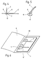
- Fig. 4 eine Teilvergrößerung des Befestigungsbereiches eines der Heftstreifen des Schnellhefters, gemäß Fig. 3,
- Fig. 5 eine perspektivische Teildarstellung des Befestigungsendes des Heftstreifens, der bei dem Schnellhefter der Fig. 1 bis 4 verwendet ist,
- Fig. 6 die perspektivische Darstellung einer zweiten Ausführungsform eines Schnellhefters, gemäß der Neuerung im aufgeklappten Zustand,
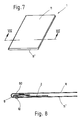
- Fig. 7 den Schnellhefter der Fig. 6 im geschlossenen Zustand und
- Fig. 8 schließlich den Schnitt durch den Schnellhefter der Fig. 7 längs der Linie VIII-VIII.
- 1 is a schematic, perspective view of a first embodiment of a folder according to the innovation in the opened state,
- 2 the flat file of FIG. 1 in the closed state,
- Fig. 3 shows the enlarged section through 2 along the line III-III,
- 4 is a partial enlargement of the fastening area of one of the stitching strips of the flat file, according to FIG. 3,
- 5 is a partial perspective view of the fastening end of the binding strip which is used in the flat file of FIGS. 1 to 4,
- 6 is a perspective view of a second embodiment of a flat file according to the innovation in the opened state,
- Fig. 7 the flat file of Fig. 6 in the closed state and
- Fig. 8 finally the section through the flat file of Fig. 7 along the line VIII-VIII.
In den Fig. 1 und 2 ist ein Schnellhefter (1) gezeigt, der aus einem in bekannter Weise um eine Knicklinie (14) faltbaren Doppelblatt besteht, in dem einzelne Papierblätter (4), die mit Lochungen (3) versehen sind, eingeheftet sind. Dies geschieht mit Hilfe von zwei Heftstreifen (2), die an dem unteren Blatt (6′) in noch zu beschreibender Weise mit einem Ende befestigt sind und durch die Lochungen (3) hindurchgezogen werden. Die Heftstreifen (2) werden dann mit ihren freien Enden in einen Schlitz (5) im oberen Blatt (6) eingeführt und durch einen zweiten Schlitz (5′) von der Außenseite des oberen Blattes (6) aus wieder nach innen gezogen. Dabei sind die beiden Schlitze (5 und 5′) in einem Abstand (a) zueinander angeordnet, der so gewählt ist, daß die Heftstreifen (2) keine scharfe Umknickung erfahren, sondern im wesentlichen flach durch das Deckblatt (6) hindurchgeführt sind.1 and 2, a flat file (1) is shown, which consists of a double sheet foldable in a known manner around a fold line (14), in which individual paper sheets (4), which are provided with perforations (3), are stapled . This is done with the help of two tack strips (2) which are attached to the lower sheet (6 ') in one manner to be described with one end and are pulled through the perforations (3). The tack strips (2) are then inserted with their free ends into a slot (5) in the upper sheet (6) and pulled through a second slot (5 ') from the outside of the upper sheet (6) back inwards. The two slots (5 and 5 ') are arranged at a distance (a) from one another, which is chosen so that the tack strips (2) do not experience a sharp bend, but are guided essentially flat through the cover sheet (6).
Wie aus den Fig. 3 und 4 hervorgeht, ist das Befestigungsende der Heftstreifen (2) mit einem knopfartigen Anlageende (10) versehen, das den Halt der Heftstreifen (2) an dem unteren Blatt (6′) gegen ein Durchziehen nach innen sichert. Dem Anlageknopf (10) gegenüber ist eine konisch zum freien Ende des Heftstreifens (2) hin sich verjüngende Verdickung vorgesehen, die einen Rasthaken (9) bildet. Der Rasthaken (9) entsteht dadurch, daß der untere Rand der Verdickung eine Anschlagkante gegenüber dem darunterliegenden Abschnitt (15) bildet, dessen Abmessungen in etwa jenen des übrigen Heftstreifens (2) entsprechen. Die Länge dieses Bereiches (15) zwischen dem Anschlagkopf (10) und dem Rasthaken (9) wird in etwa auf die Materialstärke des unteren Blattes (6′) des faltbaren Doppelblattes abgestimmt. Wird daher der Heftstreifen (2) ausgehend von seinem freien Ende durch eine entsprechende Schlitzöffnung im Blatt (6′) durchgeschoben, so läßt er sich dadurch festlegen, daß auch der Rasthaken (9) unter elastischer Verformung des Materiales durch die Öffnung im Blatt (6′) durchgeschoben wird, bis sich der Kopf (10) unten anlegt und die Verrastung am Rasthaken (9) erfolgt. Nach dem Einfädeln des Papieres (4) können dann in bereits beschriebener Weise die Enden der Heftstreifen (2) durch die Schlitze (5, 5′) geschoben werden.As can be seen from FIGS. 3 and 4, the fastening end of the binding strips (2) is provided with a button-like contact end (10) which secures the holding of the binding strips (2) on the lower sheet (6 ') against pulling inwards. Opposed to the contact button (10) is a thickening which tapers conically towards the free end of the tacking strip (2) and forms a latching hook (9). The latching hook (9) arises from the fact that the lower edge of the thickening forms a stop edge opposite the section (15) below, the dimensions of which correspond approximately to those of the rest of the binding strip (2). The length of this area (15) between the stop head (10) and the locking hook (9) is approximately matched to the material thickness of the lower sheet (6 ') of the foldable double sheet. Therefore, if the tacking strip (2) is pushed through a corresponding slot opening in the sheet (6 ') starting from its free end, it can be determined in that the latching hook (9) with elastic deformation of the material through the opening in the sheet (6 ') Is pushed through until the head (10) bears down and the locking on the locking hook (9) takes place. After threading the paper (4), the ends of the tack strips (2) can then be pushed through the slots (5, 5 ') in the manner already described.
Wie aus den Fig. 2, insbesondere aber Fig. 3 hervorgeht, sind die Schlitze (5, 5′) dadurch gebildet, daß zwei Laschen (8 und 8′) aus dem Material des Deckblattes (6) ausgestanzt werden, und zwar so, daß ihre freie Kanten (8a bzw. 8a′) jeweils voneinander wegweisen. Die Schlitze (5, 5′) werden daher von diesen freien Kanten (8a, 8a′) der Laschen (8, 8′) und den entsprechenden Stanzkanten im Deckblatt (6) gebildet, wobei sich beim Durchschieben des Heftstreifens (2) die Laschen (8, 8′) jeweils nach unten abbiegen und unter ihrer Eigenelastizität am Heftstreifen (2) anliegen.As can be seen from Fig. 2, but in particular Fig. 3, the slots (5, 5 ') are formed in that two tabs (8 and 8') are punched out of the material of the cover sheet (6), namely, that their free edges (8a and 8a ') point away from each other. The slots (5, 5 ') are therefore formed by these free edges (8a, 8a') of the tabs (8, 8 ') and the corresponding punched edges in the cover sheet (6), the tabs being pushed through when the binding strip (2) is pushed through (8, 8 ') bend downwards and bear against the adhesive strip (2) under their own elasticity.
Beim Ausführungsbeispiel sind in vorteilhafter Weise die Heftstreifen (2) und das aus den Blättern (6 und 6′) bestehende Doppelblatt aus Kunststoffmaterial, beispielsweise aus Polypropylen oder Polyäthylen, hergestellt. Die Verwendung dieses Materiales macht die gezeigte Ausführung möglich, ohne daß Verstärkungsmaßnahmen im Bereich der ausgestanzten Schlitze (5, 5′) vorzusehen sind. Der Heftstreifen (2) wird an den Laschen (8, 8′) und im übrigen am Material des Deckblattes (6) ohne nennenswerte scharfe Umlenkungen geführt. Der Schlitz (5) bzw. die Endkante (8a) der Lasche (8) ist dabei, wie Fig. 3 zeigt, in etwa so gelegt, daß er bei geschlossenem Schnellhefter (Fig. 2) in etwa oberhalb der Befestigungsstelle (7) des Heftstreifens (2) liegt, allerdings ist er etwas von der Faltkante (14) aus zum freien Ende (16) des Schnellhefters versetzt angeordnet. Der Streifen gleitet dadurch auch in der geschlossenen Lage in seinen durch die Laschen (8, 8′) und die Kanten der Schlitze (5, 5′) gegebenen Führungen. Es ist daher ohne weiteres möglich, den Schnellhefter gemäß Fig. 1 zu öffnen, ohne daß der Heftstreifen sich irgendwie verklemmt. Es wird daher möglich, das eingeheftete Papier sehr leicht aufzublättern, weil zwischen Befestigungsstelle und dem ersten Schlitz (5) im aufgeschlagenen Zustand (Fig. 1) eine große freie Länge des Heftstreifens (2) zur Verfügung steht, auf dem die Lochungen (3) leicht hin und her geschoben werden können. Beim Schließen des Schnellhefters gleitet der Heftstreifen (2) in seinen Führungen an den Laschen (8, 8′) und den Schlitzkanten der Schlitze (5, 5′) in umgekehrter Richtung. Er schiebt sich wieder mehr in seine Führungen hinein, so daß sein freies Ende, das aus dem Schlitz (5′) herausläuft, wieder länger wird. Aufgrund der gewählten Ausführung ist in dieser geschlossenen Lage (s. Fig. 3) ein ungewolltes Herausfallen von abgeheftetem Papier nicht möglich. Durch die leichte Schrägführung des Heftstreifens (2) im Bereich zwischen den beiden, etwa parallel verlaufenden Blättern (6, 6′), wird auch dann, wenn der Schnellhefter mit der Faltkante (14) nach oben gehalten wird, ein Herausfallen des Papieres verhindert. Das Eigengewicht des Papieres nämlich drückt den Heftstreifen (2) gegen den ersten Schlitz (5) und gegen die freie Kante (8a) der Lasche (8), an der im wesentli chen das Papiergewicht aufgenommen wird. Im übrigen wird auch das freie Ende des Heftstreifens (2) von innen durch den Papierstapel gegen die Innenseite des Deckblattes (6) gedrückt, so daß auch dadurch eine Sicherung des abgehefteten Stapel Papiers gewährleistet ist.In the embodiment, the booklet strips (2) and the leaves (6 and 6 ') are advantageously Double sheet made of plastic material, for example made of polypropylene or polyethylene. The use of this material makes the embodiment shown possible without reinforcement measures being provided in the area of the punched-out slots (5, 5 '). The tacking strip (2) is guided on the tabs (8, 8 ') and, moreover, on the material of the cover sheet (6) without any appreciable sharp deflections. The slot (5) or the end edge (8a) of the tab (8) is, as shown in FIG. 3, placed approximately so that it is approximately above the fastening point (7) of the when the folder is closed (FIG. 2) Binding strip (2) lies, but it is somewhat offset from the folded edge (14) to the free end (16) of the folder. The strip thus slides in the closed position in its guides given by the tabs (8, 8 ') and the edges of the slots (5, 5'). It is therefore readily possible to open the folder according to FIG. 1 without the binding strip jamming in any way. It is therefore possible to open the stapled paper very easily, because between the fastening point and the first slot (5) in the opened state (Fig. 1) there is a large free length of the binding strip (2) on which the perforations (3) can be easily moved back and forth. When the folder is closed, the binding strip (2) slides in its guides on the tabs (8, 8 ') and the slot edges of the slots (5, 5') in the opposite direction. He pushes himself back into his guides so that his free end, which runs out of the slot (5 '), becomes longer again. Due to the design chosen, in this closed position (see FIG. 3) an unwanted falling out of filed paper is not possible. Due to the slight inclination of the binding strip (2) in the area between the two, approximately parallel sheets (6, 6 '), even if the flat file is held with the folding edge (14) up, the paper will not fall out. The weight of the paper presses the booklet strip (2) against the first slot (5) and against the free edge (8a) of the tab (8), on which in essence Chen the paper weight is recorded. In addition, the free end of the binding strip (2) is pressed from the inside through the paper stack against the inside of the cover sheet (6), so that this also ensures that the stapled paper is secured.
Vorteil der neuen Ausführung ist es, daß zum Aufblättern lediglich das Doppelblatt geöffnet werden muß, um schon das leichte Umblättern zu ermöglichen.The advantage of the new design is that only the double page has to be opened to open the page to enable easy turning.
Die Fig. 6 bis 8 zeigen eine weitere Ausführungsvariante, bei der der Heftstreifen (2) bei geschlossenem Schnellhefter (1), gemäß Fig. 7, nicht zu sehen ist. Dies wird dadurch erreicht, daß in das gefaltete Doppelblatt, das aus den beiden gegeneinander faltbaren Blättern (11 und 11′) besteht, eine zusätzliche Falthalterung (60) eingesetzt wird, die beispielsweise mit Hilfe der Rastbefestigung des Heftstreifens (2) unmittelbar an die Innenseite des unteren Blattes (11′) angeheftet wird. In diesem Fall muß der Bereich (15) des Heftstreifens (2) so ausgelegt sein, daß er in etwa den Materialstärken des Blattes (11′) und des Faltsteges (60) entspricht. Der obere Faltteil des Faltsteges (60) ist in gleicher Weise wieder mit den Schlitzen (5, 5′) ausgebildet, wie das schon anhand der Fig. 1 bis 5 erläutert wurde. In diesem Fall muß zum Aufblättern die Deckseite (11) geöffnet werden und dann die Oberseite des Faltsteges (60) aufgeklappt werden. Die Schlitze (5, 5′) sind im gleichen Abstand (a) zueinander angeordnet, wie dies schon bei dem anderen Ausführungsbeispiel beschrieben worden ist. Auch hier können die Schlitze (5, 5′) durch ausgestanzte Laschen gebildet werden.6 to 8 show a further embodiment variant, in which the binding strip (2) cannot be seen when the fast-action folder (1) is closed, as shown in FIG. 7. This is achieved in that in the folded double sheet, which consists of the two sheets (11 and 11 ') which can be folded against one another, an additional folding holder (60) is used, for example with the aid of the snap fastening of the tacking strip (2) directly to the inside of the lower sheet (11 ') is attached. In this case, the area (15) of the binding strip (2) must be designed so that it corresponds approximately to the material thicknesses of the sheet (11 ') and the folding web (60). The upper folding part of the folding web (60) is formed in the same way again with the slots (5, 5 '), as has already been explained with reference to FIGS. 1 to 5. In this case, the cover side (11) must be opened for opening and then the top of the folding web (60) must be opened. The slots (5, 5 ') are arranged at the same distance (a) from one another, as has already been described in the other embodiment. Again, the slots (5, 5 ') can be formed by punched tabs.
Der neue Schnellhefter eignet sich auch zum Abheften von EDV-Papier (Papierstreifen der elektronischen Datenverarbeitung), das an beiden Rändern gelocht ist und in der Regel in einer Zick-Zack-Faltung abgelegt wird. In diesem Fall werden die Heftstreifen so weit außen angeordnet, daß sie durch je eines der Löcher an den Rändern gezogen, im übrigen aber in gleicher Weise gehalten werden, wie bei den gezeigten Ausführungsbeispielen.The new flat file is also suitable for filing EDP paper (paper strips for electronic data processing), which is perforated on both edges and is usually filed in a zigzag fold. In this case, the booklet strips are arranged so far outside that they are pulled through one of the holes at the edges, but otherwise in the same Be kept as in the embodiments shown.
Claims (11)
Applications Claiming Priority (2)
| Application Number | Priority Date | Filing Date | Title |
|---|---|---|---|
| DE8803353U | 1988-03-12 | ||
| DE8803353U DE8803353U1 (en) | 1988-03-12 | 1988-03-12 | folder |
Publications (2)
| Publication Number | Publication Date |
|---|---|
| EP0332804A2 true EP0332804A2 (en) | 1989-09-20 |
| EP0332804A3 EP0332804A3 (en) | 1990-08-16 |
Family
ID=6821768
Family Applications (1)
| Application Number | Title | Priority Date | Filing Date |
|---|---|---|---|
| EP89100674A Withdrawn EP0332804A3 (en) | 1988-03-12 | 1989-01-17 | Fast binder |
Country Status (3)
| Country | Link |
|---|---|
| US (1) | US4940352A (en) |
| EP (1) | EP0332804A3 (en) |
| DE (1) | DE8803353U1 (en) |
Families Citing this family (19)
| Publication number | Priority date | Publication date | Assignee | Title |
|---|---|---|---|---|
| DE10142824B4 (en) * | 2001-08-22 | 2007-11-29 | Wolfgang Dengler | Loop stapler for documents |
| USD557739S1 (en) | 2004-10-01 | 2007-12-18 | Hartley & Marks Publishers Inc. | Book with cover flap |
| USD558267S1 (en) | 2004-10-01 | 2007-12-25 | Hartley & Marks Publishers Inc. | Book with cover flap |
| USD557740S1 (en) | 2004-10-01 | 2007-12-18 | Hartley & Marks Publishers Inc. | Book with cover flap |
| USD546878S1 (en) | 2006-01-31 | 2007-07-17 | Hartley & Marks Publishers, Inc. | Cover for a book or similar article |
| USD573637S1 (en) | 2006-01-31 | 2008-07-22 | Hartley & Mark Publishers, Inc. | Cover for a book or similar article |
| USD547372S1 (en) | 2006-01-31 | 2007-07-24 | Hartley & Marks Publishers, Inc. | Cover for a book or similar article |
| USD550770S1 (en) | 2006-01-31 | 2007-09-11 | Hartley & Marks Publishers, Inc. | Cover for a book or similar article |
| USD549283S1 (en) | 2006-01-31 | 2007-08-21 | Hartley & Marks Publishers, Inc. | Cover for a book or similar article |
| USD566759S1 (en) | 2006-01-31 | 2008-04-15 | Hartley & Marks Publishers, Inc. | Thumb cut of a page or similar article |
| USD567849S1 (en) | 2006-01-31 | 2008-04-29 | Hartley & Marks Publishers, Inc. | Cover of a book or similar article |
| USD569903S1 (en) | 2006-08-02 | 2008-05-27 | Hartley & Marks Publishers, Inc. | Cover for a book or similar article |
| USD570911S1 (en) | 2006-09-27 | 2008-06-10 | Hartley & Marks Publishers, Inc. | Book |
| US20090152859A1 (en) * | 2007-12-14 | 2009-06-18 | Supriti Bharma | Collection of sheets of paper and methods of forming a collection of sheets of paper |
| RU2378125C2 (en) * | 2008-03-28 | 2010-01-10 | Алексей Романович Барсов | Method for making paper file |
| USD633731S1 (en) | 2010-07-09 | 2011-03-08 | Hartley & Marks Publishers, Inc. | Display stand |
| USD637016S1 (en) | 2010-07-09 | 2011-05-03 | Hartley & Marks Publishers, Inc. | Display stand |
| US10500890B2 (en) * | 2015-06-30 | 2019-12-10 | ACCO Brands Corporation | Flexible binding mechanism |
| US11613141B2 (en) * | 2020-01-17 | 2023-03-28 | Jacek Tuszynski | Binding device for paper and other items |
Family Cites Families (11)
| Publication number | Priority date | Publication date | Assignee | Title |
|---|---|---|---|---|
| US2139843A (en) * | 1936-03-17 | 1938-12-13 | Fearon D Moore | Binder |
| DE1024922B (en) * | 1955-03-21 | 1958-02-27 | Paul Widany | Folder with a line-up device for punched documents |
| CH373020A (en) * | 1958-06-12 | 1963-11-15 | Broxten Rudolf Brinkmann To | Loose-leaf binders made from two cover covers and with at least one aligning device formed from two flexible aligning tongues |
| DE1200254B (en) * | 1960-12-20 | 1965-09-09 | Soennecken Fa F | Loose-leaf binder with a line-up device made from flexible, flexible lines |
| DE1229498B (en) * | 1965-07-31 | 1966-12-01 | Rudolf Brinkmann To Broxten | Flat file with one inside pocket |
| DE1959537U (en) * | 1967-02-14 | 1967-05-03 | Regis Ges M B H | TOP STRIP MADE OF PLASTIC OR OTHER NON-METALLIC MATERIAL FOR STAPLERS, STAPLING STRIPS, ETC |
| DE1277195B (en) * | 1967-12-07 | 1968-09-12 | Rudolf Brinkmann To Broxten | Fastening device for elastically flexible strings on a carrier |
| US4261664A (en) * | 1978-07-17 | 1981-04-14 | Crawford Industries, Inc. | One-piece report binder |
| US4256411A (en) * | 1978-12-15 | 1981-03-17 | National Blank Book Company, Inc. | File folder with integral loose leaf binder rings |
| DE3511304A1 (en) * | 1985-03-28 | 1986-10-02 | Hans 7000 Stuttgart Vetter | File |
| DE3530632A1 (en) * | 1985-08-28 | 1987-03-05 | Merz & Vetter Gmbh | FILTER DEVICE FOR SHEET LAYERS |
-
1988
- 1988-03-12 DE DE8803353U patent/DE8803353U1/en not_active Expired
-
1989
- 1989-01-17 EP EP89100674A patent/EP0332804A3/en not_active Withdrawn
- 1989-03-08 US US07/320,524 patent/US4940352A/en not_active Expired - Fee Related
Also Published As
| Publication number | Publication date |
|---|---|
| DE8803353U1 (en) | 1988-05-05 |
| US4940352A (en) | 1990-07-10 |
| EP0332804A3 (en) | 1990-08-16 |
Similar Documents
| Publication | Publication Date | Title |
|---|---|---|
| EP0332804A2 (en) | Fast binder | |
| DE3015901C2 (en) | Spring clip for holding sheets of paper together or the like. | |
| DE2302365A1 (en) | STRINGING SYSTEM FOR PERFORATED PAPER STACKS OR THE LIKE. IN FOLDERS, FOLDERS AND SIMILAR REGISTRATION COLLECTORS | |
| DE2644824B2 (en) | Hanging folder | |
| DE3530632A1 (en) | FILTER DEVICE FOR SHEET LAYERS | |
| DE2206662C3 (en) | Blade holder | |
| DE10142824B4 (en) | Loop stapler for documents | |
| DE4039555C2 (en) | ||
| DE3813578C1 (en) | Suspension filing strip | |
| DE2119422B2 (en) | Filing folder for punched documents | |
| DE1078537B (en) | Line-up device made of plastic for folders | |
| DE8702107U1 (en) | Device for filing punched sheets | |
| AT411894B (en) | CLAMP FOR CLAMPING LEAVES | |
| DE2231115A1 (en) | LIFTING DEVICE FOR LOOSE LEAF STAPLING | |
| DE1118751B (en) | Folder, in particular loose-leaf binders, with an aligning device made up of two elastically flexible aligning tongues | |
| DE102014101292A1 (en) | Bindeclip for pile-like mounting of perforated leaves | |
| DE559430C (en) | Device for holding punched sheets together by means of two or more rows | |
| DE1536520C (en) | Sample book | |
| DE19941219C1 (en) | Printed sheet clip is M-shaped with centre angle section between outer arms provided with pin opening corresponding to sheet edge holes and integral tongue ebnt over sheet budle edge | |
| DE2800055A1 (en) | Document file with one piece retainer - has retaining strip flexibly connected to retainer plate by wire or cord | |
| DE7223755U (en) | Line-up device for loose-leaf stitching | |
| DE8808381U1 (en) | Device for fixing a stack or individual sheets with perforations on the edge in loose-leaf binders or register folders | |
| DE2538418A1 (en) | Filing mechanism for sheets of paper - has flexible filing tongues and cover ledges with side attachments | |
| DE1203225B (en) | Folder, in particular loose-leaf binders, with a stringing device made of elastically flexible stringing tongues | |
| EP1036670A2 (en) | Folder with strip for cover |
Legal Events
| Date | Code | Title | Description |
|---|---|---|---|
| PUAI | Public reference made under article 153(3) epc to a published international application that has entered the european phase |
Free format text: ORIGINAL CODE: 0009012 |
|
| AK | Designated contracting states |
Kind code of ref document: A2 Designated state(s): AT BE CH DE ES FR GB IT LI NL |
|
| PUAL | Search report despatched |
Free format text: ORIGINAL CODE: 0009013 |
|
| AK | Designated contracting states |
Kind code of ref document: A3 Designated state(s): AT BE CH DE ES FR GB IT LI NL |
|
| 17P | Request for examination filed |
Effective date: 19910125 |
|
| 17Q | First examination report despatched |
Effective date: 19920922 |
|
| STAA | Information on the status of an ep patent application or granted ep patent |
Free format text: STATUS: THE APPLICATION IS DEEMED TO BE WITHDRAWN |
|
| 18D | Application deemed to be withdrawn |
Effective date: 19930203 |